Suvaranjan Sutar![]() | Sachindra Kumar Rout*
| Sachindra Kumar Rout*![]() | Jnana Ranajan Senapati
| Jnana Ranajan Senapati![]() | Kamalakanta Muduli
| Kamalakanta Muduli![]() | Bikash Ranjan Moharana
| Bikash Ranjan Moharana![]()
© 2025 The authors. This article is published by IIETA and is licensed under the CC BY 4.0 license (http://creativecommons.org/licenses/by/4.0/).
OPEN ACCESS
This study investigates the thermo-hydraulic performance of a solar air heater (SAH) enhanced with triangular ribs on the absorber plate. The analysis examines three distinct rib configuration-oriented perpendicular to the airflow, with simulations conducted using ANSYS Fluent to solve conservation of mass, conservation of momentum, and energy conservation equations in a 2D domain. The aluminum absorber plate is exposed to a uniform heat flux with relative roughness pitch (RRP) ranging from 7.33 to 20.66. Reynolds numbers (Re) vary between 4000 and 18,000. The study evaluates the impact of Reynolds number and relative roughness pitch on thermal and hydraulic performance, using an ANOVA model to isolate the effects of individual parameters. Increasing Reynolds number and optimizing roughness pitch significantly enhance the thermo-hydraulic efficiency of the SAH. Specific configurations of triangular ribs improve heat transfer while maintaining manageable pressure drops. The research highlights the potential of ribbed absorber plates to improve the efficiency of SAHs under varying flow and geometric conditions. The research highlights the potential of ribbed absorber plates to improve the efficiency of SAHs under varying flow and geometric conditions.
solar, energy, air heater, ANOVA, CFD
Solar air heaters (SAHs) are vital devices for harnessing solar energy and converting it into thermal energy. Despite their straightforward construction and extensive applications in crop drying, space heating, and domestic heating, the thermodynamic performance of SAHs is often limited by the low thermal conductivity of air as the working fluid. To address this limitation, researchers have explored various design modifications, such as adding heat-storing materials, increasing absorber plate roughness, and incorporating structural elements like fins, ribs, and baffles to enhance heat transfer.
Incorporating triangular ribs on the absorber plate significantly enhances heat transfer efficiency due to increased turbulence in the flow. The performance improvement varies with the Reynolds number and relative roughness pitch, with optimal values yielding the highest thermo-hydraulic performance. To analyze the effect of different triangular rib configurations on the thermo-hydraulic performance of a solar air heater. To evaluate the influence of Reynolds number and relative roughness pitch on heat transfer and flow resistance. To identify the optimal rib configuration and operational parameters for maximizing performance. By addressing these questions and objectives, the study seeks to provide insights into the design and optimization of SAHs for improved thermal efficiency. Numerical simulations using ANSYS Fluent are employed to quantify the effects of rib-induced turbulence under varying flow and geometric conditions.
Karmane and Tikekar [1] exploited grit of metal as a roughness element, reporting enhancements of 178% and 213%. They also achieved a thermal efficiency ranging from 10% to 30%. In their experimental work on a solar air heater, Sharma and Kalamkar [2] observed a Thermal Efficiency Ratio (TER) is less than one as 0.967 at a measured Reynolds number. Bopche and Tandale [3] lead experiments on U-type ribs within the SAH and reported a Nusselt number of 2.82 along with a FFER of 3.72. Mangrulkar et al. [4] conducted both investigational and numerical analyses on a flow cross type heat exchanger with level cryptic tubes. An extreme TER of 1.35 was witnessed for a Prandtl number (Pr) of 1.5 at a Reynolds number (Re) of 21,000. Bhattacharyya et al. [5] analyzed heat removal and friction factors in turbulent flow by aligned and stunned angular-cut baffles. A TER of 2.9 was proposed for a Prandtl number (Pr) of 0.1 with a cutting angle of 60°.
Chamoli et al. [6] conducted a numerical investigation by using anchor-shaped vortex generator on a circular tube, formulating various pitch ratios, anchor annex aspect ratios, and Reynolds numbers. Their outcomes indicated a maximum TER of 1.72 for PR=1, annex aspect ratio=0.4, and Re=3000. Ambade and Lanjewar [7] carried out an experimental investigation using regular arc break staggering elements as coarseness features on a solar hoarder plate, achieving a maximum TER of 1.41. Behura et al. [8] conducted an experiment on transverse circular section rib roughness on all rims of the SAH, without the end side. They apparent thermo-hydraulic performance improvements ranging from 20% to 75%. Lanjewar et al. [9] conveyed experimental enhancements in a w-type roughened rib SAH and resolved that the result of w-down rib configurations was greater to w-up rib and V-shaped rib structures. Balaras [10] categorized surface enhancement methods into three main types: surface methods - This technique is used for roughened surface; fluid methods - This category encompasses methods such as fluid vibrations and the use of fluid additives; compound methods - These involve combinations, such as the use of vibrations with roughened surfaces, or the pairing of perforations with corrugations.
Patel [11] accomplished a numerical comparison of solar air heater performance using several roughness profiles, including rectangular, isosceles triangular, semi-circular, circular wire, blends of quarter-circle, square, triangle, and the NACA airfoil outline. It was concluded that the NACA airfoil rib provided the best thermo-hydraulic performance among the studied outlines. Yadav and Thapak [12] studied several rib profiles by different scholars and found that among these, multi V-shaped rib coarseness with a slit significantly enhances the Nusselt number, though at the cost of a greater pressure drop. Additionally, their study revealed that arc-shaped ribs provide superior overall thermo-hydraulic performance equalled to other bumpiness geometries. Verma and Prasad [13] achieved a fine thermo-hydraulic performance of 71% by using very less dia wires as coarse bases, with the superlative results occurring at a jaggedness Reynolds number (e⁺) of 24. Sahu and Bhagoria [14] explored transverse fragmented ribs and witnessed an 83.5% increase in efficiency at a pitch (P) of 20 under exact flow conditions.
Layek et al. [15] conveyed that the extreme amplification of the Nusselt number (Nu) was reached with a 180° chamfer, particularly for transverse chamfered and V-shaped grooves.
Karwa and Chauhan [16] found that a mass movement rate of air below 0.04 kg/s•m² significantly enhanced heat removal in their study of discrete ribs oriented at 60° V-down. Hans et al. [17] taken different V-type ribs on the absorber plate. As compared with smooth plate, they suggest the result improved by five and six times, respectively. Aharwal et al. [18] examined a SAH enhanced with essential continual distinct ribs, focusing on the lack of width and lack of position of the rib turbulators. They observed a total augmentation in the Nusselt number (Nu) and friction factor (fr) by factors of 2.83 and 3.60, respectively. Tanda [19] examined a rectangular passageway with rectangular, square, and V-type ribs at two angles of 45° and 60°. He resolved that crosswise damaged ribs with a PTHR (P/e) of 4 and 8 provided the maximum heat removal improvement below similar mass movement rate and impelling influence conditions. Sivakumar et al. [20] conducted a thermodynamic study of an SAH with fins on the receiver plate surface. They found that the SAH with pin-fins achieved a supreme growth in energy efficacy and energy advance of 12% and 11%, respectively, compared to a flat plate. Manjunath et al. [21] analyzed the flow and heat transfer behavior of a SAH with a sinusoidal ridged receiver plate. Using a wavelength of 0.160m, a feature ratio of 1.5, and a Reynolds number of 8000, they observed a thermal efficiency of 64%. Pandey and Bajpaye [22] investigated a SAH with a shot-blasted V-type receiver plate and conveyed a supreme thermal efficiency ratio of 1.57 for a mass movement rate of 0.01kg/s.
Sawhney et al. [23] conducted an experiment using delta winglets as roughness elements on the receiver surface. At a non-dimensional pitch of 3 and a Reynolds number of 4000, a TER of 2.09 was attained. Gawande et al. [24] conducted a numerical analysis by using reverse L-shaped ribs. The study found an extreme enrichment factor of 1.90 for a PTHR (P/e) of 7.14 and an e/Dh ratio of 0.042 at a Reynolds number of 15,000. Sutar et al. [25] investigated numerically the performance of parabolic rib turbulators and reported a maximum TER of 2.14 at a RRP of 16.66.
Recent research has focused on improving the performance of SAHs by using roughened absorber surfaces. The aim of the study is to numerically assess the thermal progression of SAHs with triangular roughness elements. The key goal is to examine how triangular ribs affect the thermal efficiency of SAHs. Detailed simulations of SAHs with triangular ribs were carried out using ANSYS-FLUENT version 20. The study also employs the ANOVA method to analyze how different strictures influence performance, a technique not previously used for this purpose. The investigation specifically looks at how roughness strictures, such as the PTHR (P/e) and rib height to hydraulic diameter ratio (e/Dh), along with flow variables like Reynolds number, affect heat transfer improvement and friction harm in triangular ribbed SAHs.
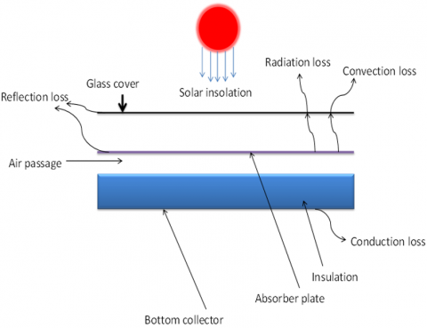
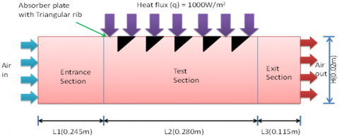
The use of solar air heaters is steadily growing, benefiting society in various ways. Heat removal in a solar air heater is shown in Figure 1 is influenced by various factors, including the inlet fluid velocity, as well as the shape, size, and orientation of the ribs. Figure 2 presents the complete fluid flow field with the test section of SAH, illustrating the division of the total movement field into three sub-domains. The design adheres to ASHRAE 93-2003 standards. The SAH duct has dimensions of height (H) = 20 mm and width (w) = 100 mm, resulting in a hydraulic diameter (Dh) of 33.3 mm. The entry and exit regions function as protective guard sections for the test section. A constant heat flux of 1000 W/m² is applied to the test unit through an electric warmer arrangement on the collector plate.The entry and exit regions function as protective guard sections for the test section.
Figure 1. Schematic of solar air heater
Figure 2. Diagram showing the various absorber plate scenarios taken into consideration for the most recent study
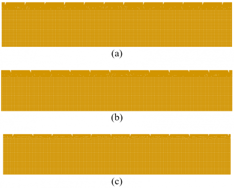
This analysis includes triangular ribs arranged transversely in three different configurations (case-1, case-2, and case-3), as portrayed in Figure 3. The analysis encompasses various aspects, including inlet flow velocity, fluid domain temperature, pressure differences owing to fluid friction, turbulent KE in the flow field, and TI at diverse relative roughness pitches and Reynolds number values.
Figure 3. Network layout for the computational field featuring the Absorber plate from case-1, case-2 and case-3
In line with the commendation of Yadav and Bhagoria [26-30] four-sided duct is used for the numerical analysis. Five pitch (p) values-11 mm, 16 mm, 21 mm, 26 mm, and 31 mm-are used, resulting in erratic comparative roughness pitches (P/e) from 7.33 to 20.66.
Five dissimilar Reynolds numbers (Re) values, ranging from 4000 to 12000, are nominated, operating within the turbulent flow regime.
The rib height remains constant at 0.0014 m, with a comparative coarseness elevation (e/Dh) of 0.042. This is a crucial factor influencing the disruption of the sticky sub-layer. The analysis covers 72 cases, taking into account the various parameters and rib arrangements (case-1, case-2, case-3).
The governing equation is addressed by pressure built solver in ANSYS FLUENT. The pressure-velocity combination was controlled using the SIMPLE, with a convergence threshold set at 10-6 for all equations. For discretization, the pressure variable employed the second-order upwind scheme.
3.1 Principal relations
We may practice a number of well-known relationships, like the Dittus-Boelter and Blasius correlations, to explore smooth ducts and conclude dimensionless quantities like the normal rubbing factor and Nusselt number. The calculated representations are as follows.
$\overline{N u_s}=0.023 R e^{0.8} P r^{0.4}$ (1)
$\bar{f}_s=0.0791 R e^{-0.25}$ (2)
The current investigation aims to survey the movement and heat removal physiognomies within a triangular-ribbed SAH duct operating under turbulent flow conditions. The quantity of heat extracted from the receiver plate is resolved by the convective equation as follows:
$Q=h A_p\left(T_p-T_b\right)$ (3)
where, $A_p$ external area of receiver plate is, $T_p$ is the temperature of receiver plate measured from fluent, and $T_b$ is the bulk mean temperature.
The regular Nusselt number for the SAH could be obtained by using the relation as:
$\overline{N u_x}=h D_h / \mathrm{k}$ (4)
$D_h=\frac{4 \times A_f}{P_w}$ (5)
The middling friction factor is defined by,
$\overline{f_r}=\frac{\{\Delta p \mid l\}}{2 \rho v^2} D_h$ (6)
The presence of ribs on the collector plate improves the degree of heat transfer, although it also results in an increased fluid friction due to the added flow obstructions. This elevated friction factor necessitates a higher pumping power.
$T E R=\frac{\left(\overline{\frac{N u_r}{N u_s}}\right)}{\left(\overline{\frac{f_r}{f_s}}\right)^{1 / 3}}$ (7)
3.2 Grid arrangement
The cell configuration in the two-dimensional (2-D) rectangular fluid flow territory is shown in Figure 3. Non-orthogonal cells are placed next to the absorber plate barrier, close to the ribs' curled surface. In the other parts of the movement field, orthogonal cells are used. Comparatively finer cells are used in the near-wall section to successfully seizure the effects of flow separation brought on by the ribs, flow circulation in front of the ribs, flow reattachment between the ribs, and the distraction of the viscous sub-layer. To lower the total number of cells, the cells in other areas of the domain are coarser. This methodology is uniformly implemented in all domain scenarios, encompassing the many categories of absorber plates (case-1, case-2, and case-3).
3.3 Grid independent test
A grid independence study was conducted for the computational process to ensure stability of the parameters under the specified conditions: a Reynolds number of 16,000, a RRP of 7.33, and a RRH of 0.042. Table 1 illustrates the variations in the Nusselt number and friction factor with different computational cell counts. It was observed that both parameters showed negligible changes at or beyond a cell count of 368,211. Consequently, the computational cell count was finalized at 368,211.
Table 1. Grid independent test
|
Serial Number |
Total Cell Count |
Nu |
f |
Nu Fluctuation Percentage |
f Fluctuation Percentage |
|
1 |
213850 |
118.23 |
0.021991 |
---- |
--- |
|
2 |
273124 |
125.12 |
0.023281 |
5.82 |
5.86 |
|
3 |
297680 |
128.61 |
0.024527 |
2.78 |
5.35 |
|
4 |
321101 |
131.86 |
0.025121 |
2.52 |
2.42 |
|
5 |
368211 |
133.46 |
0.025136 |
1.21 |
0.59 |
|
6 |
405214 |
133.89 |
0.025278 |
0.32 |
0.56 |
3.6 Numerical scheme validation
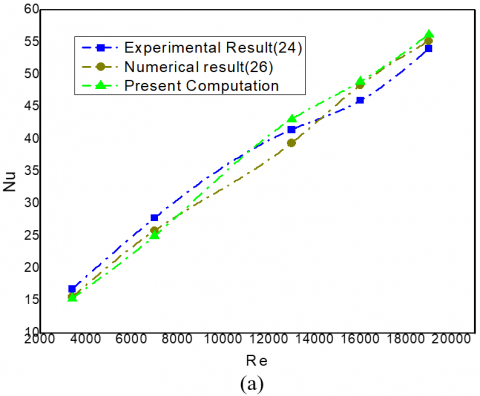
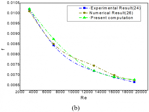
To estimate the accuracy of the present numerical model, an appraisal is made between its outcomes and those obtained by Yadav and Bhagoria [26] and Gawande et al. [24] for an unribbed (SAH), as shown in Figure 4. The plot evidently shows that the variations in the Nusselt number (Nu) and friction factor (f) from the existing analysis fall within a 4% margin compared to the outcomes of Yadav and Bhagoria [26] and Gawande et al. [24]. The turbulence model selection is very important for numerical exploration because different models affect numerical result. We have used RNG k-ε model [25].
Figure 4. Validation plots for Nu (a) and friction factor (b) of the model
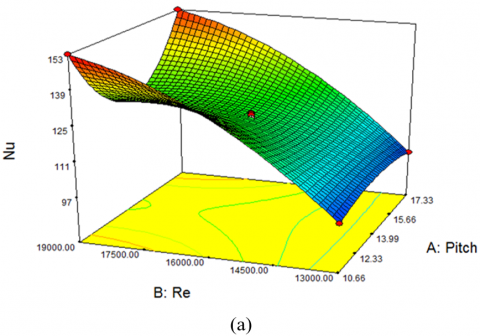
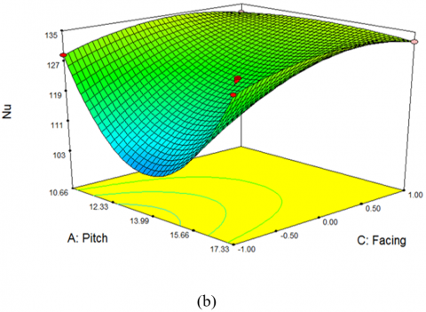
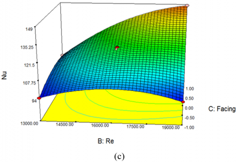
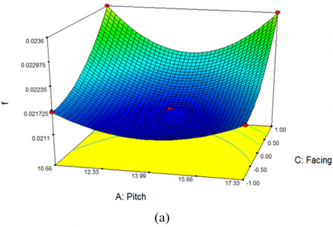
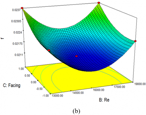
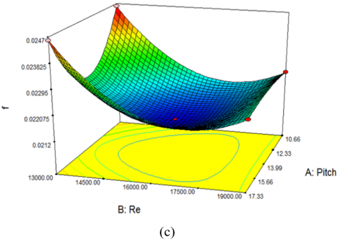
A three-factorial design with three levels each (-1, 0, +1) is employed to create a second-order response surface model. The study involves the investigation of variables (factors) such as Pitch/geometrical orientation, and Reynolds number. The values of the variables generated using the Response Surface Methodology (RSM) are input into FLUENT software to obtain the corresponding outputs, in this case, friction factor and Nusselt number. These output values are then recorded in the "response" column. The actual values of the process variables (factors), along with their range of variation and quantity, are determined through preliminary simulations and presented in Table 2. A regression model is formulated, and its outcomes are analysed utilizing Design Expert software.
Table 2. Real and coded levels of the independent variables
|
Pitch/e |
Re |
Geometrical Orientation |
Nu |
F |
|
10.66 |
13000 |
0 |
97.85 |
0.0246 |
|
17.33 |
13000 |
0 |
93.85 |
0.0225 |
|
10.66 |
19000 |
0 |
152.81 |
0.0225 |
|
17.33 |
19000 |
0 |
145.46 |
0.0205 |
|
10.66 |
16000 |
-1 |
128.71 |
0.0217 |
|
17.33 |
16000 |
-1 |
119.81 |
0.0201 |
|
10.66 |
16000 |
1 |
132.51 |
0.0236 |
|
17.33 |
16000 |
1 |
124.51 |
0.0222 |
|
13.995 |
13000 |
-1 |
94.26 |
0.0225 |
|
13.995 |
19000 |
-1 |
148.26 |
0.0203 |
|
13.995 |
13000 |
1 |
102.12 |
0.0237 |
|
13.995 |
19000 |
1 |
148.41 |
0.0221 |
Increasing the velocity flow input under periodic conditions clues to an elevated Nusselt Number. The friction factor is determined using Eq. (6). In this analysis, both bulk temperature and surface temperature are directly considered, taking into account the temperature variations across the domain. To accurately capture temperature variations at various cross-sections within the domain, a comprehensive method is chosen for Nusselt number calculation. The hydraulic diameter is a crucial factor in determining the friction factor. Figure 5 illustrates that as the velocity and Reynolds number increase, there is a significant impact on the Nusselt number. In the recent study, three different orientations are investigated: 1. Perpendicular orientation to the incoming velocity (-1), 2. Inclined orientation towards the incoming velocity (0), and 3. An alternative arrangement of perpendicular and inclined orientations (+1). The simulations are conducted with various pitch-to-rib height ratios, such as 10.66, 13.995, and 17.33, while Reynolds numbers vary from 13,000 to 19,000. Figure 6 illustrates that as the Reynolds numbers increase, the friction factors decrease, and the velocity of the movement grows. Consequently, the border layer width falls with the rise in flow velocity. This results in lower average friction factor values as Reynolds numbers increase. When the number of ribs decreases, the RRP increases. This reduction in the number of ribs in the flow field results in fewer obstructions to the flow, leading to lower pressure drop and, consequently, a diminution in the average friction factor. For all types of absorber plates, Nusselt numbers grow with increasing Reynolds numbers, regardless of the relative pitch-to-height ratio. Moreover, for a specific Reynolds number, the Nusselt number decreases as the relative roughness PTHR (P/e) increases.
Figure 5. Consequence of different geometrical strictures on Nusselt Number
Figure 6. Consequence of different geometrical parameters on friction factor
5.1 Influence of Re number variation on Nu
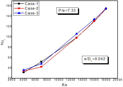
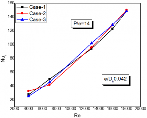
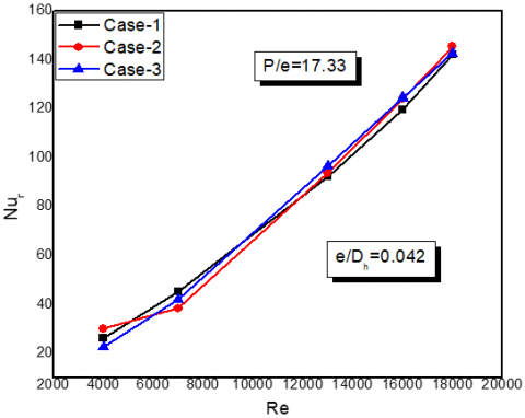
Figure 7 illustrates that as Reynolds number increase, there is a significant impact on the Nusselt number. It can also be observed from the figure that at high Reynolds numbers, the Nu value decreases with an increase in PTHR (P/e), reaching its lowest value at a PTHR (P/e) of 13.99, before increasing again thereafter. But there is no change of Nu value at low Reynolds number. Figure 7 illustrates the relationship between the regular Nu and Re number for different P/e standards. This plot corresponds to three distinct absorber plate configurations examined under a comparative RRH of 0.042. The average Nu computes the relation between convective and conductive heat transfer occurring at the heated aluminum surface. As the Re number of the movement upsurges, the convective heat removal coefficient also raises. In this framework, "RRP" refers to the relation concerning rib pitch and rib height. From the three PTHR (P/e) of 7.55, 14and 17.33 it is observed that in each type Type 3 exhibits better heat transfer performance compared to other two.
(a)
(b)
(c)
Figure 7. Graphs illustrating the relationship between Nu and Re are depicted for Type-1, Type-2 and Type-3 for (a) P/e=7.33, (b) P/e=14, and (c) P/e=17.33
5.1.1 Analysis of flow features across various Reynolds numbers
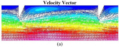
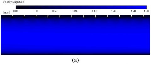
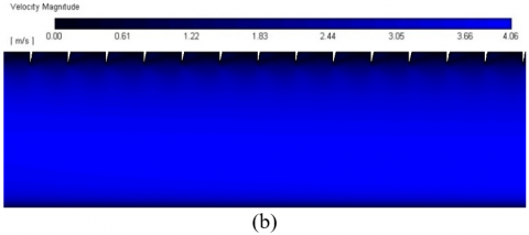
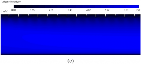
Figures 8 and 9 represent the VV and VM contours for a SAH with triangular ribs, focusing on the "case-1" configuration at various Reynolds numbers. As the Re number grows, viscosity decreases, narrowing the rapidity variation zone. The figures demonstrate that a higher Reynolds number reduces the fatness of the sticky sub-layer. The coarseness created by the ribs causes them to act like nozzles as fluid moves through the rectangular channel. Figure 8 shows the VV plot for the triangular-ribbed SAH in case-1, with a rib pitch-to-height ratio of 7.33 and a (RRH) of 0.042, at Re numbers of 3400, 7000, and 13000. The plot reveals the formation of counterclockwise secondary flow in the in between region, creating a twister. As the Re number rises, the strength of this circulation intensifies, enhancing mixing in the in between area. This mixing promotes the intake of fresh air into the in-between region, significantly boosting heat removal. Figure 9 presents VM delineations for the case-1 receiver plate with a PTHR (P/e) of 7.33 and a RRH (e/Dh) of 0.042, at Reynolds numbers of 3400, 7000, 13000, 16000, and 19000. The inlet velocity of the SAH duct is considerably lower than the outlet velocity due to the ribs accelerating the airflow in the watercourse intelligent way. Improved velocity leads to intensified turbulence, forming vortices around the triangular rib tips. This turbulence enhances heat removal from the receiver plate to the cooler air passing through the duct core.
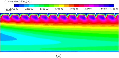
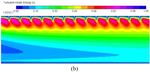
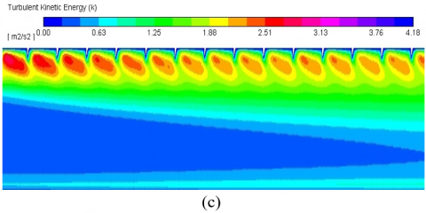
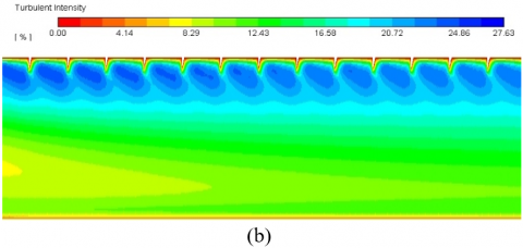
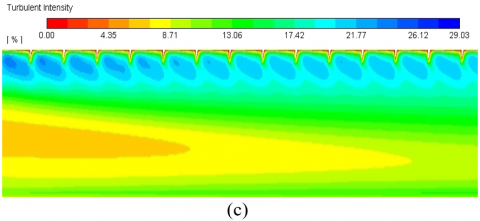
The presence of triangular ribs restricts the expansion of the boundary layer, prominent in increased turbulent intensity and turbulent kinetic energy (TKE). Figures 10 and 11 provide visual representations of this effect, with contour plots illustrating TKE and turbulent intensity, respectively.
Figure 8. VV plots of Case-1's Triangular ribbed SAH With the parameters set at P/e=7.33 and e/Dh=0.042, for Re (a) 3400, (b) 7000, and (c) 13000
Figure 9. The VM delineations for the receiver plate configuration designated as "Case-1," with RRP=7.33 and RRH=0.042, for Re (a) 3400, (b) 7000, and (c) 13000
5.1.2 Study of turbulence distinctive within the SAH
This segment scrutinizes the character of turbulence in enhancing heat removal, particularly due to the incorporation of ribs. As the Re number upsurges, the Nu also rises, driven by the intensified turbulence. Turbulent viscosity is calculated using the equation $\mu$t=ρCuK2, where turbulent kinetic energy (TKE) influences viscosity, leading to improved heat removal. TKE results from the root mean square of velocity variations, while TI represents these fluctuations as a proportion. The addition of ribs significantly boosts heat transfer, with TKE closely associated with turbulence intensity. This relationship is clearly illustrated in the contour plots.
Figures 10 and 11 present the turbulence intensity and TKE for the case-1 collector plate, with a rib PTHR (P/e) of 7.33 and a RRH (e/Dh) of 0.042, at Reynolds numbers of 3400, 7000, 13000, 16000, and 19000. The plots reveal that both turbulence parameters reach their peak between the first and second ribs. After this, they shrinkage within the inter-rib region as the flow progresses. Turbulence intensity is higher near the rib and diminishes downstream. Higher turbulence values indicate greater shear stress in those areas, with the maximum turbulence occurring near the first rib. As the flow develops further downstream, turbulence (intensity and TKE) reduces. The high-velocity airflow over the ribs promotes eddy formation in the ribbed regions, causing an increase in turbulence. This enhanced turbulence, driven by high shear stress, improves diffusion and thermal energy extraction from the solar receiver plate. The contours also show a direct correlation between increased Reynolds numbers and higher turbulence intensity, leading to more effective flow mixing.
Figure 10. TKE contours for Case-1 absorber plate for Reynolds number (a) 3400 (b) 7000 and (c) 13000
Figure 11. Outlines of turbulent intensity for the receiver plate configuration denoted as "Case-1," for Re (a) 3400, (b) 7000, and (c) 13000
5.1.3 Analysis of flow friction
The roughness is present in the ribs of the triangular section. Indeed, ribs contribute to an augmented heat transfer rate; however, they are also accountable for inducing pressure drip. This supplementary pressure drip results in resistance losses within the system. The friction loss is greater in the triangular rib as compared to the smooth one. Table 3 represents the friction factor for the different orientations of the rib.
Table 3. Relative fr factor improvement for SAH with case-1, case-2 and case-3
|
Serial Number |
Different Type of Ribs |
P/e |
Nondimensional Factor (fr/fs) |
||||
|
3400 |
7000 |
13000 |
16000 |
19000 |
|||
|
1 |
Case-1 |
7.33 |
3.4121 |
3.3056 |
3.2516 |
3.2212 |
3.2056 |
|
|
|
10.66 |
3.2216 |
3.2179 |
3.1475 |
3.1297 |
3.1191 |
|
|
|
14 |
3.1821 |
3.1585 |
3.1027 |
3.0912 |
3.0012 |
|
|
|
17.33 |
3.1017 |
2.9992 |
2.9482 |
2.9018 |
2.8870 |
|
|
|
20.66 |
3.0725 |
2.9178 |
2.9007 |
2.8937 |
2.8691 |
|
2 |
Case-2 |
7.33 |
3.4012 |
3.2941 |
3.2317 |
3.2085 |
3.2056 |
|
|
|
10.66 |
3.2071 |
3.1851 |
3.1710 |
3.1410 |
3.0819 |
|
|
|
14 |
3.1818 |
3.1371 |
3.1084 |
3.0712 |
3.0054 |
|
|
|
17.33 |
3.0978 |
2.9516 |
2.9091 |
2.8581 |
2.8392 |
|
|
|
20.66 |
3.0716 |
2.9378 |
2.8995 |
2.8421 |
2.8174 |
|
3 |
Case-3 |
7.33 |
3.3776 |
3.2948 |
3.2378 |
3.2179 |
3.2101 |
|
|
|
10.66 |
3.2375 |
3.1875 |
3.1758 |
3.1285 |
3.0712 |
|
|
|
14 |
3.2016 |
3.1721 |
3.0791 |
3.0722 |
3.0548 |
|
|
|
17.33 |
3.1386 |
3.1248 |
3.0568 |
3.0231 |
2.9612 |
|
|
|
20.66 |
3.1101 |
3.0978 |
3.0328 |
3.0178 |
2.9502 |
5.1.4 The variation of the mean friction factor as a result of changes in Reynolds number
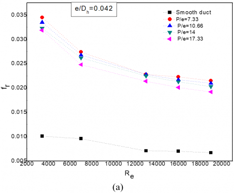
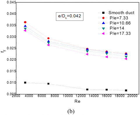
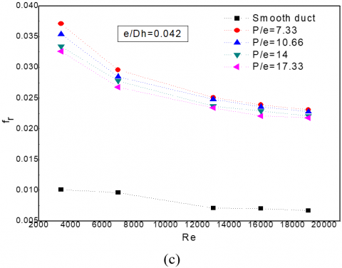
Figure 12 represents the connection between the average fr and Re number for varying P/e standards, while maintaining a constant e/Dh fraction of 0.042 across all cases (Case-1, Case-2, and Case-3). The graph reveals that the fr factor shrinks as the Re amount increases. This behavior is attributed to the increase in flow velocity, which reduces boundary layer thickness and shifts the flow away from the sticky sub-layer. Consequently, the regular fr factor diminishes with rising Re numbers.
Moreover, for a given Re number, the average fr factor shrinks with an upsurge in the RRP. A higher RRP results in fewer ribs, promoting smoother flow and reducing the pressure drop, thereby lowering the friction factor. Among the cases examined, Case-2 demonstrates superior performance in terms of friction factor or pressure drip, followed by Case-3, with Case-1 showing the highest fr factor. Additionally, the smooth duct exhibits a significantly lower friction factor compared to the ribbed duct.
Figure 12. Graphical illustration showing the association between the Reynolds number and regular fr for (a) Cases 1 (b) Cases 2, and (c), Cases 3
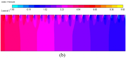
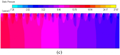
5.2 Static pressure for various (RRP)es
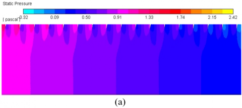
Figure 13 presents contours of static pressure distribution for Case-1 SAH, highlighting the influence of numerous coarseness pitch standards at a Re number of 13,000. The frictional flow characteristic is simply explained using static pressure contours. The triangular ribs present in the testing section hamper the airflow within the SAH duct. The movement field involves a pressure drip as a consequence of this impediment to flow. When high-speed air collides with the rib's upright surface, it slows down considerably. This incident causes a noticeable increase in pressure in that location. On the additional side of the rib, a recirculation region with reduced pressure develops after the rib tip. At the reattachment point classified as the inter-rib space, the formerly detached flow responds and attaches again to the receiver plate. At again attachment site, pressure is increased. The existence of ribs consequences in a momentous pressure lessening due to the mutual effects of flow separation, recirculation, and reattachment. The number of reattachment points decreases as the (RRP) increases. As air enters the roughened surface, it accelerates, leading to a pressure drop from the intake to the outflow region. When ribs are present in the testing area, the heat transfer rate increases, requiring greater pumping power to overcome frictional resistance.
Figure 13. Static pressure contours of the (SAH) at Re=13000 for (a) P/e=7.33, (b) P/e=10.66, and (c) P/e=14 using the Case-1 absorber plate
5.3 Exploration of liquid movement and heat removal
The THP analysis of a SAH with triangular ribs on the collector plate reveals an improvement in heat removal, accompanied by growth in impelling power due to fluid friction. The roughened surface induces complex flow patterns, including vortex formation and recirculation, enhancing heat transfer efficiency. Roughened SAHs are recognized for achieving superior heat transfer with relatively moderate pumping power requirements. For a P/e relation of 7.33 and a Re number of 16,000, the triangular rib roughened SAH achieves a Nusselt number enhancement ratio approximately 2.7924 times greater than that of a smooth duct. The highest fr factor, about 3.4121 times that of a plane duct, is observed at a P/e relation of 7.33 and a Re number of 3,400.
Defining the optimum geometry to enhance heat transfer while minimizing impelling energy can be challenging, making the thermo-hydraulic performance parameter an essential metric. Known as the TER, this parameter incorporates both the Nu and the fr factor, providing a measure of the trade-off between improved heat removal and enlarged fluid friction.
The highest TER of 1.89 occurs at a Reynolds number of 16,000. At a fixed Re number, an increase in the RRP reduces the number of ribs, resulting in a lower TER. Among the examined absorber plate designs, the Case-1 configuration demonstrates the best performance, achieving the highest TER. These results indicate that the Case-1 absorber plate is the most effective in enhancing heat removal while diminishing impelling power requirements.
The primary purpose of this learning was to illustrate the application of periodic boundary conditions in analysing complex geometries, such as relative roughness pitch. Traditionally, such simulations are resource-intensive and time-consuming, but the use of periodic conditions has significantly reduced the computational burden. As a result, even a student version of ANSYS can now handle these simulations efficiently. The obtained results exhibited minimal error, particularly in the calculation of Nu number and fr factor, which can be conveniently, determined using straightforward formulas. Furthermore, we employed the design of experiments technique in conjunction with Response Surface Methodology to further decrease the number of simulations required and gain a comprehensive understanding of the influence of key geometrical characteristics specific to SAH configurations. In the numerical analysis of an SAH with triangular ribs, two-dimensional computational domains are utilized. The output of a SAH is prejudiced by several strictures; in this study, the rib elevation was kept constant while the rib pitch was diverse across an extensive range of Re numbers. The study primarily aimed to evaluate the influence of these variations on the Nu and the (fr). The inclusion of ribs on the receiver plate markedly enhances heat transfer performance. The key findings from this investigation are summarized as follows:
|
Af |
cross-sectional area of run (m2) |
|
D |
hydraulic diameter of channel (m) |
|
E |
tallness of the ribs (m) |
|
ff |
mediocre friction factor for roughed SAH |
|
H |
deepness of duct (m) |
|
k |
conductive heat removal coefficient (w/mk) |
|
h |
convective heat transfer coefficient (w/m2k) |
|
L1 |
length of entrance section (m) |
|
L2 |
length of test section (m) |
|
L3 |
length of exit section (m) |
|
ṁ |
mass flow rate(kg/s) |
|
Nur |
Nusselt number of roughed SAH |
|
Nus |
Nusselt number of smooth SAH |
|
P |
pitch of the rib |
|
Ph |
saturated perimeter (m) |
|
Pr |
Prandtl number |
|
Re |
Reynolds number |
|
W |
duct girth |
|
w/H |
aspect fraction of the duct |
|
Ti |
inlet temperature of air (K) |
|
To |
exit temperature of air (K) |
|
Tp |
total plate temperature (K) |
|
Tb |
bulk mean hotness of the fluid (K) |
|
Ae |
operative surface zone of the absorber plate (m2) |
|
Greak letters |
|
|
Ρ |
density of functioning fluid (kg/m3) |
|
µ |
dynamic viscosity of functioning fluid (Pa.s) |
|
αk |
reverse turbulent Prandtl digit correlated with turbulence kinetic energy |
|
αε |
reverse turbulent Prandtl digit correlated with energy dissipation rate |
|
Subscripts |
|
|
s |
smooth duct |
|
r |
Roughed duct |
|
t |
turbulent flow |
|
FFER |
friction factor enhancement ratio |
|
PTHR |
pitch to height ratio |
|
RRP |
relative roughness pitch |
|
KE |
kinetic energy |
|
TI |
turbulent intensity |
|
SIMPLE |
semi-implicit method for pressure-linked equations |
|
RRH |
relative roughness height |
|
VV |
velocity vector |
|
VM |
velocity magnitude |
|
THP |
thermal hydraulic performance |
[1] Karmare, S.V., Tikekar, A.N. (2010). Analysis of fluid flow and heat transfer in a rib grit roughened surface solar air heater using CFD. Solar Energy, 84(3): 409-417. https://doi.org/10.1016/j.solener.2009.12.011
[2] Sharma, S.K., Kalamkar, V.R. (2017). Experimental and numerical investigation of forced convective heat transfer in solar air heater with thin ribs. Solar Energy, 147: 277-291. https://doi.org/10.1016/j.solener.2017.03.042
[3] Bopche, S.B., Tandale, M.S. (2009). Experimental investigations on heat transfer and frictional characteristics of a turbulator roughened solar air heater duct. International Journal of Heat and Mass Transfer, 52(11-12): 2834-2848. https://doi.org/10.1016/j.ijheatmasstransfer.2008.09.039
[4] Mangrulkar, C.K., Dhoble, A.S., Pant, P.K., Kumar, N., Gupta, A., Chamoli, S. (2020). Thermal performance escalation of cross flow heat exchanger using in-line elliptical tubes. Experimental Heat Transfer, 33(7): 587-612. https://doi.org/10.1080/08916152.2019.1704946
[5] Bhattacharyya, S., Benim, A.C., Pathak, M., Chamoli, S., Gupta, A. (2020). Thermohydraulic characteristics of inline and staggered angular cut baffle inserts in the turbulent flow regime. Journal of Thermal Analysis and Calorimetry, 140: 1519-1536. https://doi.org/10.1007/s10973-019-09094-8
[6] Chamoli, S., Lu, R., Xie, J., Yu, P. (2018). Numerical study on flow structure and heat transfer in a circular tube integrated with novel anchor shaped inserts. Applied Thermal Engineering, 135: 304-324. https://doi.org/10.1016/j.applthermaleng.2018.02.052
[7] Ambade, J., Lanjewar, A. (2019). Experimental investigation of solar air heater with new symmetrical GAP ARC GEOMETRY and staggered element. International Journal of Thermal Sciences, 146: 106093. https://doi.org/10.1016/j.ijthermalsci.2019.106093
[8] Behura, A.K., Prasad, B.N., Prasad, L. (2016). Heat transfer, friction factor and thermal performance of three sides artificially roughened solar air heaters. Solar Energy, 130: 46-59. https://doi.org/10.1016/j.solener.2016.02.006
[9] Lanjewar, A., Bhagoria, J.L., Sarviya, R.M. (2011). Experimental study of augmented heat transfer and friction in solar air heater with different orientations of W-Rib roughness. Experimental Thermal and Fluid Science, 35(6): 986-995. https://doi.org/10.1016/j.expthermflusci.2011.01.019
[10] Balaras, C.A. (1990). A review of augmentation techniques for heat transfer surfaces in single-phase heat exchangers. Energy, 15(10): 899-906. https://doi.org/10.1016/0360-5442(90)90071-9
[11] Patel, C. (2015). CFD analysis of artificially roughened solar air heater. M. Tech., Doctoral Dissertation, Dissertation, Nirma University, India. https://repository.nirmauni.ac.in/jspui/handle/123456789/6248?mode=full.
[12] Yadav, A.S., Thapak, M.K. (2014). Artificially roughened solar air heater: Experimental investigations. Renewable and Sustainable Energy Reviews, 36: 370-411. https://doi.org/10.1016/j.rser.2014.04.077
[13] Verma, S.K., Prasad, B.N. (2000). Investigation for the optimal thermohydraulic performance of artificially roughened solar air heaters. Renewable Energy, 20(1): 19-36. https://doi.org/10.1016/S0960-1481(99)00081-6
[14] Sahu, M.M., Bhagoria, J.L. (2005). Augmentation of heat transfer coefficient by using 90 broken transverse ribs on absorber plate of solar air heater. Renewable Energy, 30(13): 2057-2073. https://doi.org/10.1016/j.renene.2004.10.016
[15] Layek, A., Saini, J.S., Solanki, S.C. (2009). Effect of chamfering on heat transfer and friction characteristics of solar air heater having absorber plate roughened with compound turbulators. Renewable Energy, 34(5): 1292-1298. https://doi.org/10.1016/j.renene.2008.09.016
[16] Karwa, R., Chauhan, K. (2010). Performance evaluation of solar air heaters having v-Down discrete rib roughness on the absorber plate. Energy, 35(1): 398-409. https://doi.org/10.1016/j.energy.2009.10.007
[17] Hans, V.S., Saini, R.P., Saini, J.S. (2010). Heat transfer and friction factor correlations for a solar air heater duct roughened artificially with multiple v-ribs. Solar Energy, 84(6): 898-911. https://doi.org/10.1016/j.solener.2010.02.004
[18] Aharwal, K.R., Gandhi, B.K., Saini, J.S. (2008). Experimental investigation on heat-transfer enhancement due to a gap in an inclined continuous rib arrangement in a rectangular duct of solar air heater. Renewable Energy, 33(4): 585-596. https://doi.org/10.1016/j.renene.2007.03.023
[19] Tanda, G. (2004). Heat transfer in rectangular channels with transverse and V-Shaped broken ribs. International Journal of Heat and Mass Transfer, 47(2): 229-243. https://doi.org/10.1016/S0017-9310(03)00414-9
[20] Sivakumar, S., Siva, K., Mohanraj, M. (2019). Experimental thermodynamic analysis of a forced convection solar air heater using absorber plate with pin-fins. Journal of Thermal Analysis and Calorimetry, 136: 39-47. https://doi.org/10.1007/s10973-018-07998-5
[21] Manjunath, M.S., Karanth, K.V., Sharma, N.Y. (2018). Numerical investigation on heat transfer enhancement of solar air heater using sinusoidal corrugations on absorber plate. International Journal of Mechanical Sciences, 138: 219-228. https://doi.org/10.1016/j.ijmecsci.2018.01.037
[22] Pandey, N.K., Bajpai, V.K. (2016). Experimental investigation of heat transfer augmentation using multiple arcs with gap on absorber plate of solar air heater. Solar Energy, 134: 314-326. https://doi.org/10.1016/j.solener.2016.05.007
[23] Sawhney, J.S., Maithani, R., Chamoli, S. (2017). Experimental investigation of heat transfer and friction factor characteristics of solar air heater using wavy delta winglets. Applied Thermal Engineering, 117: 740-751. https://doi.org/10.1016/j.applthermaleng.2017.01.113
[24] Gawande, V.B., Dhoble, A.S., Zodpe, D.B., Chamoli, S. (2016). Experimental and CFD investigation of convection heat transfer in solar air heater with reverse L-shaped ribs. Solar Energy, 131: 275-295. https://doi.org/10.1016/j.solener.2016.02.040
[25] Sutar, S., Rout, S.K., Senapati, J.R., Barik, D., Dennison, M.S., Praveenkumar, S. (2024). Numerical investigation on the thermohydraulic performance of a solar air heater duct featuring parabolic rib turbulators on the absorber plate. Case Studies in Thermal Engineering, 64: 105399. https://doi.org/10.1016/j.csite.2024.105399
[26] Yadav, A.S., Bhagoria, J.L. (2013). A CFD (computational fluid dynamics) based heat transfer and fluid flow analysis of a solar air heater provided with circular transverse wire rib roughness on the absorber plate. Energy, 55: 1127-1142. https://doi.org/10.1016/j.energy.2013.03.066
[27] Yadav, A.S., Bhagoria, J.L. (2014). A numerical investigation of turbulent flows through an artificially roughened solar air heater. Numerical Heat Transfer, Part A: Applications, 65(7): 679-698. https://doi.org/10.1080/10407782.2013.846187
[28] Yadav, A.S., Bhagoria, J.L. (2014). A CFD based thermo-hydraulic performance analysis of an artificially roughened solar air heater having equilateral triangular sectioned rib roughness on the absorber plate. International Journal of Heat and Mass Transfer, 70: 1016-1039. https://doi.org/10.1016/j.ijheatmasstransfer.2013.11.074
[29] Yadav, A.S., Bhagoria, J.L. (2014). A numerical investigation of square sectioned transverse rib roughened solar air heater. International Journal of Thermal Sciences, 79: 111-131. https://doi.org/10.1016/j.ijthermalsci.2014.01.008
[30] Yadav, A.S., Bhagoria, J.L. (2015). Numerical investigation of flow through an artificially roughened solar air heater. International Journal of Ambient Energy, 36(2): 87-100. https://doi.org/10.1080/01430750.2013.823107