Shaimaa Ghalip*![]() | Riyadh S. Al Turaihi
| Riyadh S. Al Turaihi![]()
© 2025 The authors. This article is published by IIETA and is licensed under the CC BY 4.0 license (http://creativecommons.org/licenses/by/4.0/).
OPEN ACCESS
A thorough numerical examination of vertical ribbed duct heat transfer performance due to rib height and geometry adjustments under air-water two-phase flow conditions is provided. The numerical analysis through the CFD approach implemented both the VOF model with k-ε turbulence model to simulate three rib patterns including circular, triangular and rectangular types across different air and water velocity ranges from 4.38 to 13.16 m/s and 0.328 to 0.986 m/s, respectively. Heat transfer performance as well as flow behavior depend heavily on rib height together with their shape. Triangular ribs demonstrated maximum thermal efficiency through their ability to produce extensive turbulence and mixing among all tested shapes. Tests revealed a maximum heat transfer coefficient of 11,200 W/m²·K for triangular ribs during peak water velocity along with peak air velocity whereas circular and rectangular ribs exhibited maximum heat transfer coefficients of 10,600 W/m²·K followed by 10,000 W/m²·K, respectively. Triangular ribs performed the best by transferring 2,600 W of maximum heat energy which surpassed the heat energy reached by circular (2,500 W) and rectangular (2,300 W) configurations. Vertical two-phase systems achieve highest efficiency in heat transfer when their ribs are properly optimized for triangular geometry that leads to excellent performance in cooling applications.
rib height, two-phase flow, heat transfer coefficient, vertical ribbed channel
The heat transfer operations for two-phase flow systems remain essential for engineering applications that use nuclear reactors together with refrigeration systems and electronic cooling devices. Heat transfer enhancements in these systems are necessary for maintaining operational effectiveness together with thermal steadiness. The modification of flow channel internal surfaces through rib implementation proves to be an effective approach for better heat transfer performance. The addition of ribs enhances heat transfer performance by disturbing the boundary layer and generating turbulence, which increases the heat transfer rate. The behavioral effects of two-phase flows become intricate when designing rib structures in vertical channels because gravity plays a vital role in these systems. The heat transfer coefficient together with flow pattern and pressure drop depends most strongly on rib height which serves as a crucial geometric parameter of ribs. The paper evaluates how changes in rib height affect heat transfer efficiency in vertical channels under two-phase flow scenarios through numerical methods. The research employs detailed computational modeling to study rib geometry effects on flow behavior for improving the performance of high-performance thermal systems.
Several studies have examined heat transfer enhancement in ribbed channels, focusing on various rib geometries, flow regimes, and working fluids. Yang et al. [1] and Li et al. [2] demonstrated the influence of rib spacing and buoyancy effects on heat transfer in supercritical flows using CFD models. Other researchers, such as Ravi et al. [3] and Weihing et al. [4], highlighted the role of turbulence closure models in improving heat transfer predictions within ribbed channels. Khwanchit et al. [5]. Several studies have investigated the enhancement of heat transfer in ribbed or structured internal cooling channels, focusing on rib configurations, rib scale, and hybrid enhancement techniques. Kong et al. [6] experimentally examined miniature ribs of different shapes (transverse, inclined, and V-shaped) incorporating periodic slits, revealing significant improvements in turbulent heat transfer. Dinh et al. [7] conducted numerical simulations on truncated-root ribs for internal turbine blade cooling, showing notable enhancements in both heat transfer and flow uniformity. Kim et al. [8] used naphthalene sublimation to analyze extended ribs in a leading-edge channel, providing experimental validation for performance trends.
Wang et al. [9] explored the optimization of cross-scale ribs through numerical methods, offering insights into multiscale interactions between flow and surface features. The influence of rib orientation was studied by Bukht Majmader et al. [10], who evaluated bidirectional rib arrangements in a two-pass cooling channel. Kotowicz et al. [11] investigated helically ribbed tubes under CFD modeling, identifying clear distinctions in heat transfer behavior compared to smooth channels. A different approach was adopted by Colleoni et al. [12], combining riblets with vortex generators to boost wall/fluid heat exchange effectiveness.
Furthermore, Kilicaslan and Sarac [13] performed an experimental study on heat transfer enhancement in compact heat exchangers with different rib geometries. Holographic interferometry was employed in their work to gain useful insights into rib shape’s effect on local flow behavior and thermal distribution, indicating that the disturbance at the rib improves convective heat transfer. Pulsating flow effects on ribbed channels were analyzed by Yang et al. [14], who highlighted the importance of dynamic flow regimes in heat transfer behavior. Micro-scale rib features were the focus of Zheng et al. [15], while Wang et al. [16] integrated machine learning and additive manufacturing to develop high-performance ribbed mini-channels. Finally, DNS and advanced numerical methods were utilized by Choi et al. [17], Zhu et al. [18], and Pandya and Ekkad [19] to evaluate the fluid dynamic and thermal characteristics in ribbed channels under varying geometries and Reynolds numbers. The effect of single-sided rib structures on internal cooling performance has also been investigated in recent numerical works. Ris et al. [20] analyzed turbulent flow and heat transfer in a rectangular channel with internal ribs placed on only one wall at a 45° inclination. Their simulations, conducted across high Reynolds number regimes, demonstrated notable asymmetry in flow development and strong enhancement in local heat transfer along the ribbed surface. The study also emphasized the trade-off between heat transfer improvement and pressure drop penalty, providing valuable insight for high-performance turbine blade cooling applications.
This study provides a comprehensive numerical investigation of the effect of rib height and rib shape (triangular, circular, and rectangular) on the heat transfer performance in vertical ribbed ducts operating under air-water two-phase flow conditions. Unlike previous studies that primarily focused on single-phase flows or limited rib configurations, the present work employs detailed CFD simulations using the Volume of Fluid (VOF) multiphase model combined with the k-ε turbulence model to simulate realistic two-phase flow behavior.
The unique contribution of this research lies in its simultaneous evaluation of multiple rib shapes across a wide range of air and water velocities, offering new insights into how rib geometry enhances turbulence, fluid mixing, and heat transfer under complex two-phase interactions. The findings provide valuable design recommendations for optimizing ribbed heat exchanger systems used in industrial, electronic, and nuclear cooling applications.
2.1 Domain design
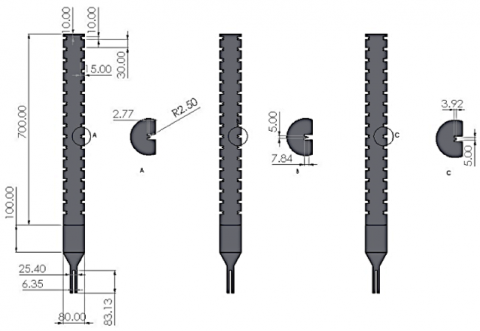
The beginning of numerical simulation requires developers to create a three-dimensional geometric model representing the vertical ribbed duct with full accuracy. SolidWorks served as the robust CAD software for creating the simulation domain design with experimental setup-driven precise dimensions. The design included the duct body along with ribs of different heights along with duct entrances and exits as well as heat transfer areas. Ribs' geometrical properties took central focus during design while engineers concentrated on representing the fundamental features that would affect fluid motion and thermal exchange as the ribs strongly influence turbulence development and heat transfer results. The investigation of rib height influence on system performance included extensive modeling of different rib varieties. The designed geometry underwent export to a compatible file format (STEP or IGES) to proceed with processing in ANSYS Fluent. SolidWorks provided an accurate design platform that enabled smooth meshing and simulation transition by reducing the amount of geometry-related errors that can occur during preprocessing. Three types of fins were used: triangular, circular and rectangular, with the same surface areas, as shown in Figure 1.
Figure 1. Domain dimensions of vertical ribbed duct
2.2 Governing equations
The numerical simulation of two-phase flow and heat transfer in the vertical ribbed duct is based on the fundamental conservation equations of fluid dynamics. ANSYS Fluent 19 solves these equations using the finite volume method (FVM) for each control volume in the computational domain. The main governing equations include the continuity, momentum, and energy equations. In the case of two-phase flow, the Volume of Fluid (VOF) model is used to capture the interface between the liquid and gas phases.
The general form of the continuity equation for incompressible flow is:
$\frac{\partial \rho}{\partial t}+\nabla \cdot(\rho \vec{v})=0$ (1)
where,
$\rho$ is the fluid density
$\vec{v}$ is the velocity vector
$t$ is time
The momentum conservation equation is derived from Newton's second law and is expressed as:
$\frac{\partial(\rho \vec{v})}{\partial t}+\nabla \cdot(\rho \vec{v} \vec{v})=-\nabla p+\nabla \cdot\left[\mu\left(\nabla \vec{v}+\nabla \vec{v}^T\right)\right]+\rho \vec{g}+\vec{F}$ (2)
where,
$p$ is pressure
$\mu$ is the dynamic viscosity
$\vec{g}$ is gravitational acceleration
$\vec{F}$ includes external body forces and interfacial tension in VOF
The energy equation governs heat transfer within the fluid domain:
$\frac{\partial(\rho E)}{\partial t}+\nabla \cdot(\vec{v}(\rho E+p))=\nabla \cdot\left(k_{e f f} \nabla T\right)+S_h$ (3)
where,
$E$ is the total energy per unit mass
$T$ is temperature
$k_{e f f}$ is the effective thermal conductivity
$S_h$ is the volumetric heat source term
Volume of Fluid (VOF) Equation
To model the interface between the liquid and gas phases, the VOF method solves an additional transport equation for the volume fraction ($\alpha$) of each phase:
$\frac{\partial \alpha_q}{\partial t}+\nabla \cdot\left(\alpha_q \vec{v}\right)=0$ (4)
where,
$\alpha_q$ is the volume fraction of phase $q$ (e.g., water or air)
The properties such as density and viscosity in each cell are computed based on the volume fraction of the phases.
2.3 Boundary conditions
All surface boundaries of the vertical ribbed duct model received necessary boundary conditions for creating an accurate experimental replication with dependable simulation outputs. The domain boundaries' conditions function as essential elements to define the flow and thermal field behavior thus enabling convergence together with proper physical simulation results. These boundary conditions which were implemented during the study follow the specifications below:
Type: Velocity inlet (water :0.328,0.657,0.986 m/s, air: 4.38,8.773,13.16 m/s)
The duct accommodates air and water phases in a Two-phase flow condition. Experimental flow velocity rates serve as the velocity parameter definition at the inlet section. The applied temperature remains constant at the fluid inlet measurement value. Each phase maintains its volume fraction determination (air holds 0.2 fraction and water holds 0.8 fraction depending on the flow conditions).
Type: Pressure outlet
Gauge Pressure: 0 Pa (atmospheric pressure)
A backflow condition keeps the outlet phase fractions and temperature equivalent to those established during reverse flow conditions.
Type: No-slip wall condition
The wall thermal condition implements either stable heat flux or maintains a fixed temperature depending on which simulation parameters are active.
The experimental duct material dictates the choice between aluminum and copper as wall material.
Any definition of wall roughness is possible for simulations that consider the effects of roughness.
Symmetry plane along with periodic boundary serve as the type of boundary.
The model aids in reducing the computational domain dimensions without affecting the realistic flow patterns.
Enabled: Yes
With regard to domain orientation the direction points towards -Y (or -Z) along the axis.
The modeling aims to demonstrate proper simulation of buoyancy effects and gravitational forces in vertical two-phase flow.
2.3.1 Thermal boundary condition specification
In this study, the thermal boundary condition applied to the ribbed channel walls was set as a constant heat flux. All walls were subjected to a uniform heat flux to simulate the heating conditions during the two-phase flow operation. This assumption allows accurate analysis of convective heat transfer enhancement induced by rib geometry variations. The value of the applied heat flux was kept consistent throughout all simulation cases to ensure fair comparison among different rib shapes and flow conditions.
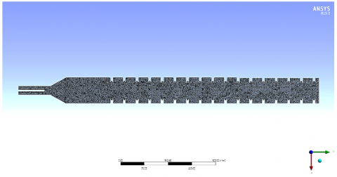
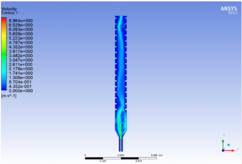
The assessment of mesh reliability served to achieve accurate and stable simulation outcomes within the CFD analysis. The evaluation process assessed mesh quality followed by a mesh sensitivity test which ensured the solution remained unaffected by mesh density and element count. The experimental tests used meshes of three different densities that were evaluated against heat transfer coefficient, pressure drop and temperature distribution measurements. The negligible difference between the medium and fine meshes in the results proved that mesh independence existed. All simulations utilized the medium mesh because it maintained both precise solutions and efficient computation. Numerical reliability of the solution was assured by continuously observing mesh quality metrics which included skewness, orthogonality, and aspect ratio measurements that displayed favorable results throughout most cells. Near the ribbed surfaces appropriate inflation layers were implemented to faithfully model boundary layer developments and local temperature and velocity gradients on the walls. The simulation results were both meaningful in practice and devoid of numerical issues because of the careful attention paid to mesh reliability (Figure 2).
The element's worth was 1542179 at this time while it was hitting the maximum velocity with the speed of 6.76 m/s as seen in Table 1.
Figure 2. Mesh generated
Table 1. Mesh independency
|
Case |
Element |
Node |
Maximum Velocity m/s |
|
1 |
845643 |
174588 |
6.98 |
|
2 |
1136570 |
223067 |
6.81 |
|
3 |
1358890 |
264568 |
6.77 |
|
4 |
1542179 |
298472 |
6.76 |
3.1 Validation
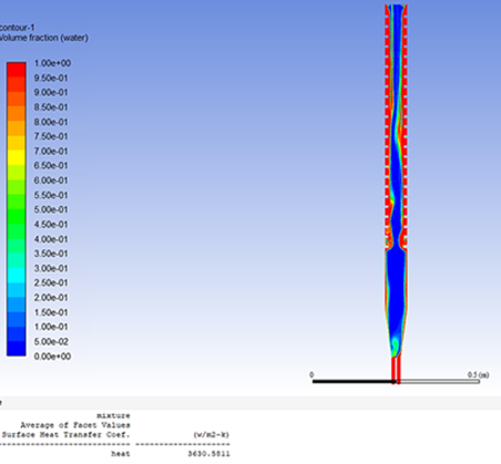
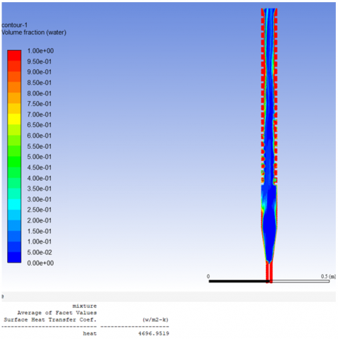
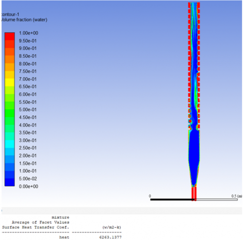
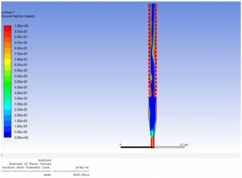
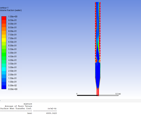
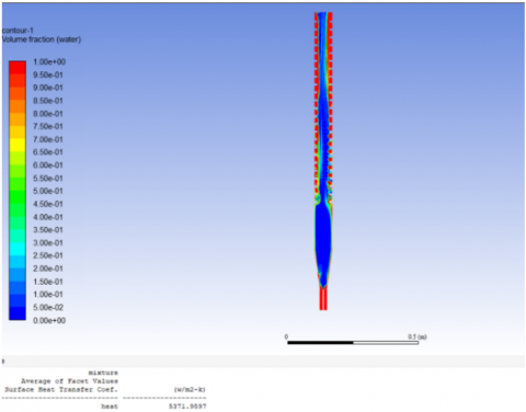
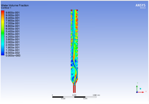
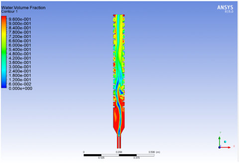
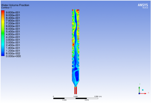
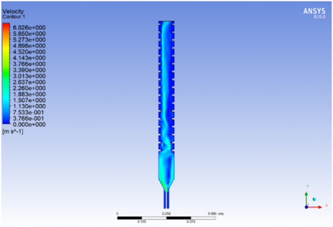
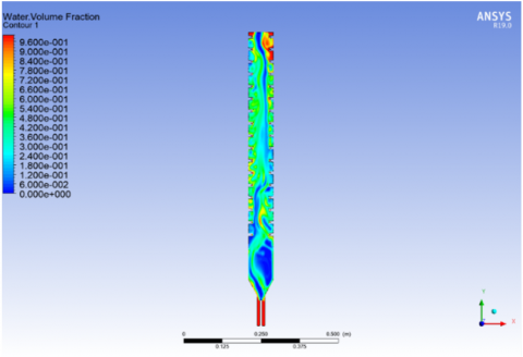
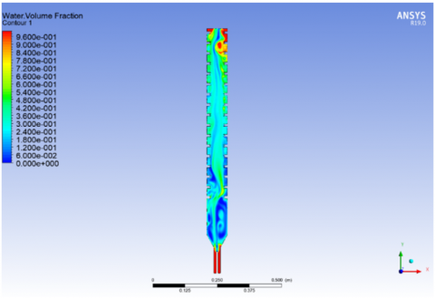
ANSYS Fluent run CFD simulations of mixtures using the multiphase model alongside k-ε turbulence model and achieved validation through experimental data and Shah’s correlation. The experimental results indicate that raising both water and air velocities leads to increased heat transfer coefficients. The wider ribs increase air movement turbulence through eddies formation thus enhancing thermal exchange and mixing performance. The research establishes that heat transfer coefficients rise with increases in both flow velocity and the e/w ratios specifically at higher flow rates in ribbed ducts. Figure 3 and Figure 4 present model validation results through comparison of the quantities at different water and air flow velocities which include volume fraction contours and heat transfer coefficient measurements. The increasing water velocity between 0.328 m/s to 0.986 m/s leads to better water distribution while producing stronger upward momentum in Figure 3 and Figure 4 that demonstrate improved mixing. The flow domain allows deeper air penetration when air velocity rises from 4.38 m/s to 13.16 m/s which leads to increased dispersion and phase interaction mechanisms. The model demonstrates its competence in representing real two-phase flow characteristics through these visual results. These findings are quantitatively validated in Figure 3 and Figure 4 through data showing that rising water velocity results in a heat transfer coefficient increase from 6100 W/m²·K to 8500 W/m²·K and rising air velocity causes the heat transfer coefficient to rise from 5800 W/m²·K to 8800 W/m²·K. Experimental findings match the predictions because increased fluid speeds create more turbulent conditions that enhance heat exchange effectiveness. The collected data demonstrate that the simulation model properly represents ribbed duct two-phase flow physics.
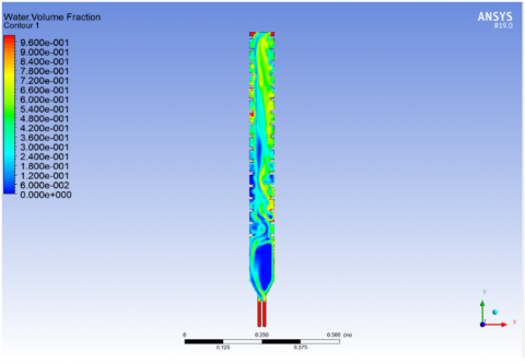
The volume of fraction contours for circular ribs shows results from three water velocities, which include (a) 0.328 m/s, (b) 0.657 m/s, and (c) 0.986 m/s. Figure 5 depicts physical alterations in the water phase distribution which occur when elevation of inlet velocity takes place inside the vertical duct with ribbed structure. In the condition of 0.328 m/s velocity the water phase concentrates at the bottom ribs creating a substantially thicker film layer which demonstrates slow movement and powerful gravitational influence. The rising efficiency of water distribution along ribs increases at a velocity of 0.657 m/s because inertial forces enhance water movement. The dynamic flow condition at 0.986 m/s produces thinner water films and improved surface wetting as well as clear upward propagation that demonstrates better mixing. The modifications create significant changes to both interface dimensions and corresponding heat transfer ability. The data shows that rising water velocity aids the reduction of phase separation and enhances flow symmetry inside the ribbed duct. Visual evidence demonstrates that rising water velocity strengthens two-phase system interaction while enhancing heat transfer performance near the ribs.
(a)
(b)
(c)
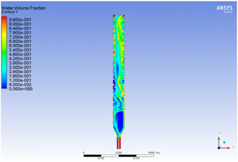
Figure 3. Volume of fraction contour of validation with different velocity of water: (a) 0.328 m/s, (b) 0.657 m/s, (c) 0.986 m/s
(a)
(b)
(c)
Figure 4. Volume of fraction contour of validation with different velocities of air: (a) 4.38 m/s, (b) 8.775 m/s, (c) 13.16 m/s
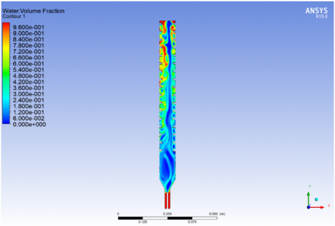
Different air velocities affect the fractional volume distribution in Figure 6 of circular ribs operating at (a) 4.38 m/s, (b) 8.775 m/s and (c) 13.16 m/s. The graphic demonstrates the water flow behavior in the ribbed vertical duct while the gas phase engages with it. The domain's upper portion contains most bubble formations at 4.38 m/s when the air volume fraction remains low because the mixing is weak and the entrainment is insufficient. As the speed of the air flow reaches 8.775 m/s the bubbles distribute throughout the medium in an unpredictable fashion which demonstrates turbulent conditions and heightened interface activities. When operated at 13.16 m/s the air phase takes control over the central region which displays intense mixing and relatively even penetration between the ribs. The increased surface renewal rates and enhanced convective heat transfer happen as a result of this phenomenon. Heat transfer performance in ribbed duct systems receives significant improvement from both gas–liquid contact enhancement and flow disturbance development when air velocity rises across the subfigures' sequence. Local recirculation zones become more substantial at increased air velocities because of circular ribs and this feature boosts thermal efficiency.
(a)
(b)
(c)
Figure 5. Volume of fraction contour of circle ribs with different velocity of water: (a) 0.328 m/s, (b) 0.657 m/s, (c) 0.986 m/s
(a)
(b)
(c)
Figure 6. Volume of fraction contour of circle ribs with different velocity of air: (a) 4.38 m/s, (b) 8.775 m/s, (c) 13.16 m/s
(a)
(b)
(c)
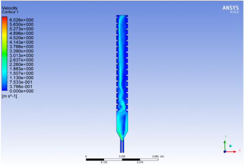
Figure 7. Velocity contour of circle ribs with different velocity of water: (a) 0.328 m/s, (b) 0.657 m/s, (c) 0.986 m/s
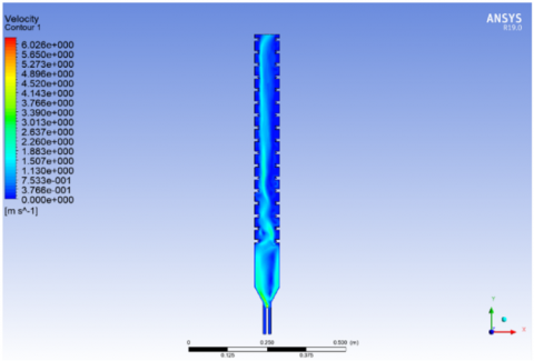
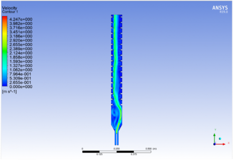
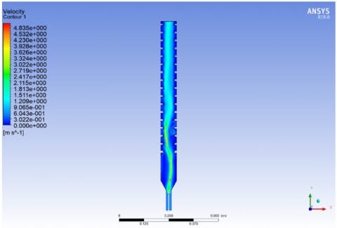
The vertical duct containing circular ribs demonstrates variable water velocity distributions at different water velocities according to Figure 7 parts (a), (b) and (c) with velocities of 0.328 m/s, 0.657 m/s and 0.986 m/s, respectively. At a flow speed of 0.328 m/s the water moves with a laminar distribution through the duct which produces minimal turbulence because penetrations between ribs remain limited. When velocity reaches 0.657 m/s, the flow distribution becomes uneven because separation occurs and recirculation forms around the ribs thus indicating turbulent conditions start to develop. Strong vortices and jet formation between rib gaps occur at the maximum velocity of 0.986 m/s making the flow both vigorous and turbulent thus intensifying shear rates and mixing strength. The flow path disruption produced by the ribs generates fast moving fluid near their edges together with slow moving recirculating zones behind them. Improved convective heat transfer occurs because fluid agitation becomes stronger when variations exist in the system. The figure demonstrates how inlet water velocity controls both the internal flow dynamics and thermal performance improvement through its effect on turbulence and rib-affected flow disturbance patterns.
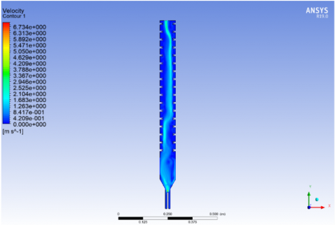
Figure 8 shows the velocity distributions of air flowing down a vertical duct containing circular ribs at three different entry air speeds which are (a) 4.38 m/s, (b) 8.775 m/s and (c) 13.16 m/s. The duct experiences a uniform air flow distribution at a velocity of 4.38 m/s with weak turbulent effects maintaining a moderate interaction between the ribs. When the air velocity reaches 8.775 m/s the velocity field undergoes substantial changes because high-speed zones appear near the rib surfaces while small recirculation regions develop behind the ribs which demonstrates intensified turbulence and stronger disturbances caused by the ribs. When the duct experiences 13.16 m/s maximum velocity the airflow pattern shows vigorous distribution resulting in substantial eddy formation between the ribs that produces robust shear forces for improved momentum exchange. The ventilation duct benefits from greater convective heat exchange because ribs inside it function as turbulence-promoting obstacles which break the boundary layer. The air velocity's rise leads to increased flow energy and turbulence that benefits thermal performance enhancement in ribbed duct systems according to the provided figure.
(a)
(b)
(c)
Figure 8. Velocity contour of circle ribs with different velocity of air: (a) 4.38 m/s, (b) 8.775 m/s, (c) 13.16 m/s
(a)
(b)
(c)
Figure 9. Volume of fraction contour of velocity of air 4.38 m/s and velocity of water 0.328 m/s at different shapes of ribs: (a) Circular, (b) triangular, (c) rectangular
Figure 9 presents volume fraction contour lines showing the impact of three different rib designs including circular and triangular as well as rectangular shapes at a constant air speed of 4.38 m/s alongside water flow of 0.328 m/s. The circular ribs produce a flow pattern with balanced mixing dynamics which demonstrates moderate water phase spread along with noticeable backflow behind the ribs. Higher turbulence generation and improved phase interaction emerge from triangular ribs because their pointed geometry causes both sharper separation zones and a more chaotic water phase dispersion. The rectangular rib design creates wider stagnant water pools behind each rib, which indicates lesser mixing effectiveness than triangular ribs produce. Different rib shapes create distinctive flow behaviors because they control how much the flow becomes obstructed and how effectively the interface returns to its original position. Triangular ribs produce the most severe breakdown of flowing elements that boosts gas–liquid interaction strengths to improve heat transfer levels. The circular shape of ribs creates stable flow disturbance for interfacial mixing yet delivers more effective results than rectangular ribs. The presented figure demonstrates that structural changes in rib shape control the spatial arrangement between two-phase mixtures in the duct.
(a)
(b)
(c)
Figure 10. Velocity contour of velocity of air 4.38 m/s and velocity of water 0.328 m/s at different shapes of ribs: (a) Circular, (b) triangular, (c) rectangular
The velocity distribution in Figure 10 shows how 4.38 m/s air and 0.328 m/s water velocities affect the three rib configurations of (a) circular, (b) triangular, and (c) rectangular shape. The flow around circular ribs distributes velocity equally and reveals moderate behind-rib recirculation pools that enable uniform blending and flow recovery. Strong vortices along with high shear regions appear near the sharp edges of triangular ribs due to the intensified velocity gradient thus indicating enhanced momentum exchange and turbulence. The fluid flow experiences enhanced convective transport as result of energetic eddies created by this shape which makes the fluid speed up before it abruptly slows down. The rectangular-shaped ribs generate large stagnant zones which increase separation and flow stagnation over broad areas behind the structure. The dead zones decrease fluid motion effectiveness and reduce the heat transfer potential due to minimal fluid interaction with heat surfaces. The research figure shows that rib shape variations strongly affect the fluid flow patterns because triangular designs create the most complex velocity behavior followed by circular ribs yet rectangular structures produce flow boundaries and dead zones.
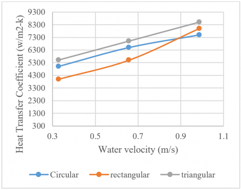
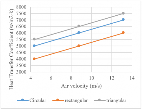
The heat transfer coefficient reacts to water velocity variations using circular and rectangular and triangular rib patterns when air moves at 4.38 m/s consistently (Figure 11). The heat transfer coefficient raises along all rib shapes as water velocity enhances from 0.328 m/s to 0.986 m/s because stronger liquid movement promotes better convective heat transfer. With water velocity at 0.328 m/s the circular ribs exhibit heat transfer coefficient value of 5900 W/m²·K while rectangular ribs produce 5200 W/m²·K and triangular ribs deliver 6300 W/m²·K. During water flow at 0.657 m/s the heat transfer coefficients become 6900 W/m²·K, 6100 W/m²·K, and 7300 W/m²·K, respectively. The combination of high water flow rate at 0.986 m/s generates the highest thermal conductance values of 8300 W/m²·K for circular shape ribs and 8900 W/m²·K for triangular ribs while rectangular ribs achieve 7800 W/m²·K. The triangular ribs maintain the top position in thermal performance because their pointed design creates maximum turbulence and disrupts the flow path. Thermal performance from circular ribs exhibits balanced characteristics whereas rectangular ribs produce the lowest heat transfer enhancement by creating flow stagnation zones behind their flat surfaces. The figure demonstrates a mutual relationship between the arrangement of rib types and water movement velocity within two-phase fluid systems.
Figure 11. Heat transfer coefficient with air velocity 4.38 m/s and different water velocities at different shapes of ribs
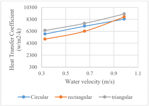
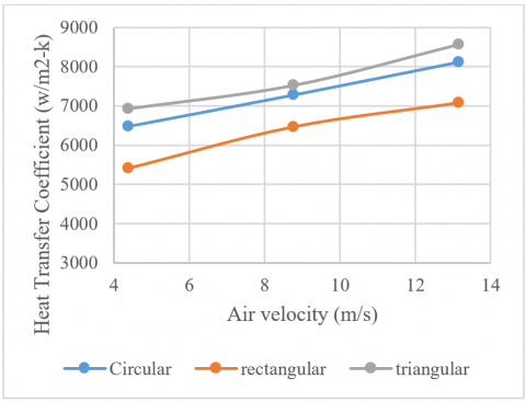
Figure 12. Heat transfer coefficient with air velocity 8.773 m/s and different water velocities at different shapes of ribs
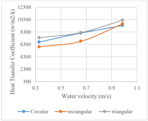
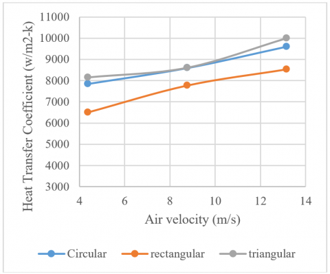
Figure 13. Heat transfer coefficient with air velocity 13.16 m/s and different water velocities at different shapes of ribs
The change in heat transfer coefficient depends on water velocity along with three different rib shapes displayed in Figure 12 under a maintained air velocity at 8.775 m/s. When water velocity rises between 0.328 m/s and 0.986 m/s the heat transfer coefficient improves for every rib shape because of enhanced fluid movement. The heat transfer coefficients reach 6400 W/m²·K for circular ribs at 0.328 m/s and 6900 W/m²·K for triangular ribs at this same velocity. At 0.328 m/s, rectangular ribs have a heat transfer coefficient value of 5900 W/m²·K. When water velocity increases to 0.657 m/s there will be an increase in heat transfer coefficient values to about 7400 W/m²·K, 6800 W/m²·K, and 7900 W/m²·K. The highest coefficient values of 8800 W/m²·K are observed for circular ribs at 0.986 m/s while rectangular ribs show 8500 W/m²·K and triangular ribs reach 9600 W/m²·K. High heat transfer occurs with triangular ribs since their pointed profile creates stronger turbulence effects. The stability of circular ribs remains constant while rectangular ribs show lower performance at lower water velocity levels. Coldwater velocity in combination with different rib shapes enhances heat transfer according to this data point which highlights the significant effect of rib dimensions and water flow speed.
The heat transfer coefficient shows a distinct pattern with rising water velocity for circular and rectangular while triangular ribs (see Figure 13) under high air velocity conditions of 13.16 m/s. The heat transfer coefficient rises dramatically for all rib types when water velocity moves from 0.328 m/s to 0.986 m/s because better turbulence and convective movement occur. The heat transfer coefficient measured at 0.328 m/s water speed shows 6900 W/m²·K for circular ribs, 6400 W/m²·K for rectangular ribs and 7500 W/m²·K for triangular ribs. The coefficients measure at 7800 W/m²·K, 7000 W/m²·K, and 8200 W/m²·K as water velocity reaches 0.657 m/s. The maximum heat transfer coefficient measuring 11,200 W/m²·K occurs at 0.986 m/s water velocity in triangular rib tubes followed by 10,600 W/m²·K in circular ribs then 10,000 W/m²·K in rectangular ribs. Triangular ribs show persistent superiority among all the tested cross-sections by generating enhanced flow disruption and better mixing under intense flow conditions. At peak fluid velocity systems with triangular ribs perform best in heat transfer because these geometries create the greatest degrees of turbulence since their shapes enhance fluid disturbance.
Figure 14. Heat transfer coefficient with water velocity 0.328 m/s and different air velocities at different shapes of ribs
The heat transfer coefficient measurement under constant water velocity of 0.328 m/s revealed its dependence on air velocity growth for circular and rectangular and triangular rib geometries as shown in Figure 14. A rise in air velocity from 4.38 m/s to 13.16 m/s results in substantial improvements of the heat transfer coefficient for all rib patterns because gas–liquid interaction and turbulence intensity both strengthen. The heat transfer coefficient reaches 4700 W/m²·K with rectangular ribs and 5400 W/m²·K for circular ribs whereas triangular ribs display a heat transfer rate of 6000 W/m²·K at the air velocity of 4.38 m/s. Heat transfer coefficients under the 8.775 m/s intermediate air velocity increased to 5600 W/m²·K, 6200 W/m²·K and 6900 W/m²·K, respectively. The coefficients measure 6400 W/m²·K for rectangular and 7100 W/m²·K for circular and 7700 W/m²·K for triangular ribs when the test velocity reaches 13.16 m/s. Triangular ribs show superior thermal performance due to their pointed design, which maximizes turbulence and disturbs the flow path effectively. Synthetic results demonstrate that rectangular-shaped ribs demonstrate the minimum heat enhancement among all geometries because recirculation zones restrict their effectiveness. The experimental findings demonstrate both faster air flow intensifies passive heat transfer mechanisms and maintains that rib shape shapes thermal conductivity performance.
A study of heat transfer coefficient variation against rising air velocity exists in Figure 15 through its examination of circular, rectangular, and triangular rib shapes under fixed water velocity at 0.657 m/s. Heat transfer coefficients grew from 4.38 m/s to 13.16 m/s air velocity for every rib shape due to enhancing convective heat transfer by increasing airflow intensity. The heat transfer coefficient attains values of 6000 W/m²·K for rectangular ribs and 6800 W/m²·K for circular ribs and 7400 W/m²·K for triangular ribs when measured at 4.38 m/s air velocity. The measurements for heat transfer coefficient show 6700 W/m²·K for rectangular ribs as well as 7600 W/m²·K for circular ribs and 8100 W/m²·K for triangular ribs at 8.775 m/s air velocity. The thermal coefficient at 13.16 m/s air velocity values 7200 W/m²·K for rectangular ribs and 8300 W/m²·K for circular ribs along with 8800 W/m²·K for triangular ribs. Better heat dissipation occurs due to improved turbulence and enhanced interfacial renewal when air velocities grow stronger. Triangular ribs demonstrate superior heat transfer performance in this condition followed by circular ribs which show reliable results between the other shapes tested. The coefficient of rectangular ribs presents some improvement yet remains the least effective for thermal improvement during elevated airflow speeds.
Figure 15. Heat transfer coefficient with water velocity 0.657 m/s and different air velocities at different shapes of ribs
The heat transfer coefficient measurements grew higher with rising air velocity at 0.986 m/s water velocity for circular, rectangular, and triangular rib configurations (Figure 16). The heat transfer coefficient elevates for all shapes between air velocities of 4.38 m/s to 13.16 m/s because higher air speeds create better turbulence and enhance gas–liquid interaction. At 4.38 m/s the heat transfer coefficients reach approximately 7600 W/m²·K for rectangular ribs and 8800 W/m²·K for circular and triangular ribs. The heat transfer coefficients in this scenario reach 8300 W/m²·K for rectangular, 9200 W/m²·K for circular and 9400 W/m²·K for triangular ribs while air moves at 8.775 m/s. The highest air velocity of 13.16 m/s leads to maximum coefficients where rectangular ribs achieve 9000 W/m²·K and circular and triangular ribs reach 10,000 W/m²·K and 10,600 W/m²·K, respectively. The experimental data demonstrate that air velocity together with rib shape are important factors determining heat transfer behavior. Sharp edges on triangular ribs grant maximum heat enhancement because they create stronger flow disruption. The circular rib configuration achieves thermal efficiency on par with the circular design while rectangular rib efficiency remains lower because of enlarged wake regions and weakened vortex behavior.
Figure 16. Heat transfer coefficient with water velocity 0.986 m/s and different of air velocity at different shape of ribs
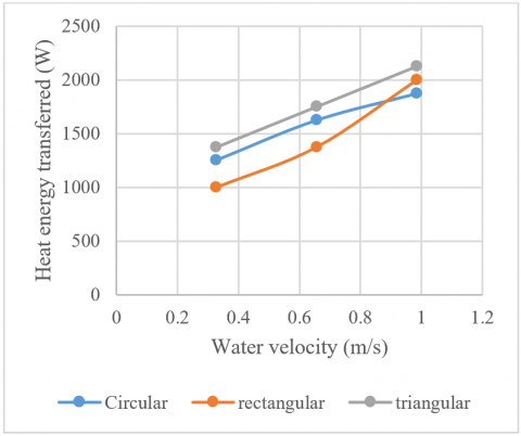
Figure 17. Heat energy transferred with air velocity 4.38 m/s and different of water velocity at different shape of ribs
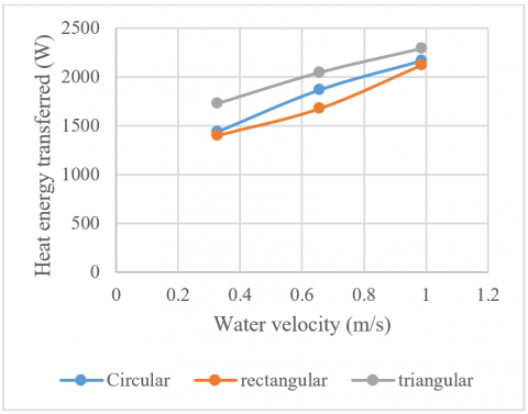
Figure 17 shows how heat energy changes with rising water velocity when using circular and rectangular and triangular rib shapes under a consistent air velocity of 4.38 m/s. The growing water velocity from 0.328 m/s to 0.986 m/s leads to a continuous rise in heat energy transfer across the different rib configurations. At a water velocity of 0.328 m/s the heat energy measures 1,200 W for rectangular ribs while circular ribs reach 1,400 W and triangular ribs reach 1,500 W. The three values reach approximately 1,400 W, 1,700 W, and 1,800 W after velocity reaches 0.657 m/s. The highest heat energy observed at 0.986 m/s water velocity amounted to 1,900 W for rectangular and 2,000 W for circular and 2,200 W for triangular ribs. Triangular ribs demonstrate lasting performance superiority because their pointed design strengthens fluid turbulence and mixing that boosts thermal absorption. A circular shaped rib design provides balanced performance but rectangular shaped ribs minimize heat transfer because they create extended flow separation zones. The represented data establishes the fundamental role of both water velocity and rib shape for enhancing heat energy exchange.
Figure 18. Heat energy is transferred with air velocity 8.773 m/s and difference in water velocity at different shapes of ribs
The data in Figure 18 demonstrates how heat energy changes according to water velocity under an air flow speed of 8.775 m/s for circular, rectangular, and triangular ribs. The heat energy transfer enhances across all rib shapes due to better convective performance when water velocity rises from 0.328 m/s to 0.986 m/s. The measured heat energy transfer amounts to 1,400 W for rectangular ribs while circular ribs experience 1,600 W and triangular ribs reach 1,800 W at the 0.328 m/s water velocity. At 0.657 m/s water velocity the measured values coincide with 1,700 W, 1,900 W and 2,100 W. The heat energy reaches its maximum level of 2,100 W for rectangular ribs and it surpasses 2,200 W and finally rises to 2,350 W for triangular ribs when operating at the highest velocity of 0.986 m/s. The excellent performance of triangular ribs persists because their pointed shape generates more turbulent flow and enhances thermal exchange. The consistent enhancement from circular ribs outperforms rectangular ribs because rectangular ribs generate minimal mixing effects. Under stronger airflow conditions the energy transfer efficiency depends on both rib shape and water velocity as illustrated by this data point.
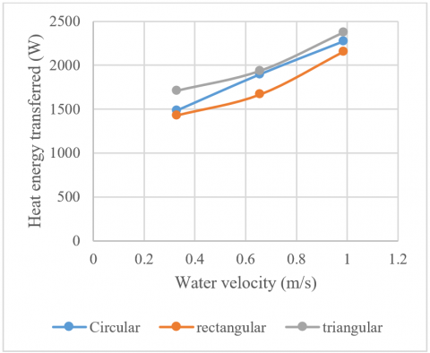
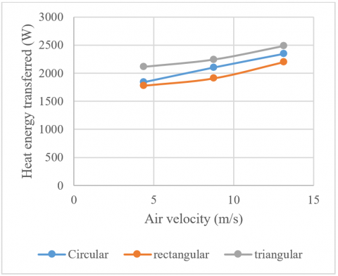
Three different rib shapes including circular and rectangular and triangular were used to measure heat energy transfer versus water velocity when air operated at a constant speed of 13.16 m/s in Figure 19. The heat energy transfer rate improves for all shapes as water velocity rises from 0.328 m/s to 0.986 m/s because enhanced flow agitation and better fluid–surface interaction occur. The changed heat energy amounts to approximately 1,600 W for rectangular ribs and 1,700 W for circular ribs and 1,900 W for triangular ribs when the velocity is set to 0.328 m/s. The heat energies belong to 1,850 W, 2,050 W, and 2,250 W ranges when the water velocity reaches 0.657 m/s. The highest water rate of 0.986 m/s enables heat transfer of 2,200 W for rectangular and 2,500 W for triangular shapes and 2,350 W for circular ribs. The triangular ribs deliver the highest energy performance because they have a pointed shape which generates powerful turbulence and maximizes the exposed surface area. The rectangular ribs demonstrate the lowest heat energy transfer enhancement among others because they experience greater flow separation leading to stagnation. The obtained data demonstrate that high velocity conditions together with an optimized rib design, effectively optimize thermal energy transfer.
Figure 19. Heat energy is transferred with an air velocity 13.16 m/s and difference of water velocity at different shapes of ribs
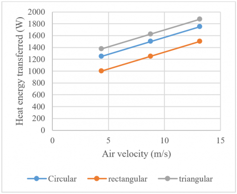
The heat energy transfer displays different patterns depending on air speed levels for circular, rectangular and triangular cross-section ribs which run at a steady water speed of 0.328 m/s as Figure 20 demonstrates. Heat transfer performance is enhanced for all rib shapes because rising air velocity ranging from 4.38 m/s to 13.16 m/s creates better airflow contact with the liquid phase. At 4.38 m/s the system delivers 1,000 W of heat energy to the surroundings for rectangular ribs and 1,300 W for circular ribs and 1,400 W for triangular ribs. The values culminate to about 1,200 W, 1,500 W, and 1,600 W at 8.775 m/s. At the maximum air velocity of 13.16 m/s, round ribs received 1,700 W and rectangular and triangular ribs each received 1,500 W and 1,850 W respectively of total heat energy transfer. The triangular rib design continually leads over the other geometries because its pointy edges promote better turbulence and superior phase interaction. Circular ribs maintain heat exchange while rectangular ribs perform poorly because their poor flow disruption capability. According to this figure the thermal energy transfer rate increases dramatically when we raise air velocity especially with improved rib configuration.
Heat energy transfer for three rib shapes (circular, rectangular, triangular) at water velocity 0.657 m/s increased according to Figure 21 as air velocity improved from 4.38 m/s to 13.16 m/s. The heat energy transferred increases for every rib type as air velocity rises from 4.38 m/s up to 13.16 m/s which demonstrates that elevated airflow speeds up turbulence creation and surface heat exchange. The heat energy transfer at 4.38 m/s reaches about 1,500 W for rectangular shapes and 1,700 W for circular shapes and 1,900 W for triangular shapes. The values correspond to 1,700 W and 1,850 W and 2,000 W at 8.775 m/s. When airflow reaches 13.16 m/s the heat energy transferred becomes approximately 2,000 W for rectangular, 2,100 W for circular and 2,200 W for triangular ribs. Due to their more intricate shape with better mixing properties the triangular ribs maintain their top performance levels. The second rate performance comes from circular ribs yet rectangular ribs enhance the process yet produce the lowest efficiency numbers. The figure demonstrates how air velocity together with rib shape combines to boost thermal energy transfer within two-phase flow systems.
Figure 20. Heat energy is transferred with water velocity 0.328 m/s and the difference in air velocity at different shapes of ribs
Figure 21. Heat energy transferred with water velocity 0.657 m/s and different of air velocity at different shape of ribs
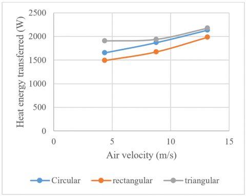
Figure 22 shows how varying air velocities affect heat transfer for three rib shapes including circular, rectangular, and triangular yet water velocity remains at 0.986 m/s. All geometries show growing heat energy transfer during the air velocity range from 4.38 m/s up to 13.16 m/s because of enhanced convective conditions. The heat energy transfer reaches around 1,800 W for rectangular, 2,000 W for circular, and 2,200 W for triangular ribs at an air velocity of 4.38 m/s. Each air velocity level of 8.775 m/s produced heat energy values of around 2,000 W for rectangular, 2,200 W for circular and 2,400 W for triangular ribs. When air flows at 13.16 m/s, heaters using rectangular, circular and triangular ribs experience energy transfers of 2,300 W, 2,500 W and 2,600 W. Flow disturbances from triangular ribs achieve optimal thermal performance because they generate heavy turbulence patterns. Proper flow enhancement comes from circular ribs yet rectangular ribs struggle due to their large wake regions. The graphical evidence demonstrates heat energy transfer optimization occurs when air velocity is high together with triangular rib configurations.
Figure 22. Heat energy is transferred with water velocity 0.986 m/s and the difference in air velocity at different shapes of ribs
3.2 Practical implications of the findings
The findings of this study provide valuable design insights for optimizing heat transfer performance in vertical ribbed channels under two-phase flow conditions. The demonstrated superiority of triangular ribs in generating higher turbulence and enhancing mixing suggests that such geometries can be effectively implemented in compact heat exchangers, electronic cooling systems, and nuclear reactor cooling circuits where space constraints and efficient thermal management are critical. Furthermore, the detailed parametric analysis on rib height and flow velocities can serve as practical guidelines for engineers to select optimal rib geometries and operational conditions in the design of advanced thermal systems involving air-water two-phase flow.
The research used numerical methods and CFD simulations to study rib height and shape influences on heat transfer coefficient in vertical ribbed ducts operating with two-phase flow. The simulated outcome establishes the fundamental importance of duct geometrical features together with fluid movement characteristics on heat transfer optimization. Triangular-shaped rib shapes demonstrated superior heat transfer coefficient performance across all flow velocities because their angular shape effectively created more turbulent fluid motion and better mixing of fluids. The maximum heat transfer coefficient exceeded 11,200 W/m²·K when water moved at 0.986 m/s while air moved at 13.16 m/s which was achieved with triangular ribs yet circular and rectangular rib performance reached only 10,600 W/m²·K and 10,000 W/m²·K, respectively. Conversation of heat energy followed the identical tendencies observed in the experiment. When operating under these peak conditions the triangular ribs reached heat energy levels of 2,600 W whereas circular ribs delivered 2,500 W and rectangular ribs reached 2,300 W. The research demonstrates that raising rib height together with using triangular rib designs results in substantial performance improvements regarding heat transfer convective rates inside two-phase vertical ducts. Increasing pressure drop needs evaluation in actual implementations due to this compensation. The investigation delivers necessary information for enhancing ribbed channel structures because of their utility in heat exchangers and cooling systems and thermal applications utilizing two-phase flow.
[1] Yang, Z., Chen, W., Chye, M.K. (2018). Numerical study on the heat transfer enhancement of supercritical CO₂ in vertical ribbed tubes. International Journal of Thermal Sciences, 145: 705-715. https://doi.org/10.1016/j.applthermaleng.2018.09.081
[2] Li, Z.H., Wu, Y.X., Tang, G.L., Lu, J.F., Wang, H. (2016). Numerical analysis of buoyancy effect and heat transfer enhancement in flow of supercritical water through internally ribbed tubes. International Journal of Thermal Sciences, 98: 1080-1090. https://doi.org/10.1016/j.applthermaleng.2016.01.007
[3] Ravi, B.V., Singh, P., Ekkad, S.V. (2017). Numerical investigation of turbulent flow and heat transfer in two-pass ribbed channels. International Journal of Thermal Sciences, 112: 31-43. https://doi.org/10.1016/j.ijthermalsci.2016.09.034
[4] Weihing, P., Younis, B.A., Weigand, B. (2014). Heat transfer enhancement in a ribbed channel: Development of turbulence closures. International Journal of Heat and Mass Transfer, 76: 509-522. https://doi.org/10.1016/j.ijheatmasstransfer.2014.04.052
[5] Khwanchit, W., Changcharoen, W., Eiamsa-ard, S. (2011). Numerical investigation of flow friction and heat transfer in channels with various shaped ribs mounted on two opposite ribbed walls. International Journal of Chemical Reactor Engineering, 9(1). https://doi.org/10.1515/1542-6580.2560
[6] Kong, D.H., Ren, S., Isaev, S., Liu, C.L., Liu, S., Niu, X.Y. (2025). Experimental investigation of turbulent heat transfer characteristics in rectangular channels with miniature transverse, inclined, and V‑shaped ribs incorporating periodic slits. International Journal of Thermal Sciences, 209: 109531. https://doi.org/10.1016/j.ijthermalsci.2024.109531
[7] Dinh, C.T., Nguyen, T.M., Vu, T.D., Park, S.G., Nguyen, Q.H. (2021). Numerical investigation of truncated‑root rib on heat transfer performance of internal cooling turbine blades. Physics of Fluids, 33(7): 076104. https://doi.org/10.1063/5.0054149
[8] Kim, T., Kim, J.H., Park, H.S., Song, H.S., Moon, H.K., Cho, H.H. (2023). Heat/mass transfer augmentation in a leading‑edge channel with extended ribs: Naphthalene sublimation experiments. International Communications in Heat and Mass Transfer, 144: 106791. https://doi.org/10.1016/j.icheatmasstransfer.2023.106791
[9] Wang, Y.B., Yan, K.C., Wang, C.X., Wang, S.Y., Zhang, B.X., Yang, Y.R., Wang, X.D. (2024). Optimization study on fluid flow and heat transfer in a rectangular channel with cross‑scale ribs for turbine blade internal cooling. Physics of Fluids, 36(12): 125109. https://doi.org/10.1063/5.0238508
[10] Majmader, F.B., Hasan, M.J. (2024). Effects of bidirectional rib arrangements on turbulent flow structure and heat transfer characteristics of a two‑pass channel for turbine blade internal cooling. International Communications in Heat and Mass Transfer, 156: 107688. https://doi.org/10.1016/j.icheatmasstransfer.2024.107688
[11] Kotowicz, J., Michalski, S., Balicki, A. (2016). Determination of technical and economic parameters of an ionic transport membrane air separation unit working in a supercritical power plant. Chemical and Process Engineering, 37(3): 359-371. https://doi.org/10.1515/cpe-2016-0029
[12] Colleoni, A., Toutant, A., Olalde, G., Foucaut, J.M. (2013). Optimization of winglet vortex generators combined with riblets for wall/fluid heat exchange enhancement. Applied Thermal Engineering, 51(1-2): 64-75. https://doi.org/10.1016/j.applthermaleng.2012.09.039
[13] Kilicaslan, I., Sarac, H.I. (1998). Enhancement of heat transfer in compact heat exchanger by different type of rib with holographic interferometry. Experimental Thermal and Fluid Science, 17(4): 339-346. https://doi.org/10.1016/S0894-1777(98)00006-5
[14] Yang, B., Gao, T.Y., Gong, J.Y., Li, J. (2018). Numerical investigation on flow and heat transfer of pulsating flow in various ribbed channels. Applied Thermal Engineering, 145: 576-589. https://doi.org/10.1016/j.applthermaleng.2018.09.041
[15] Zheng, S.F., Qiu, Y.P., Zhang, Y., Gao, S.R., Yang, Y.R., Li, H.W. (2024). Scale effect of micro ribs on the turbulent transport in an internal cooling channel. Physics of Fluids, 36(2): 025172. https://doi.org/10.1063/5.0186554
[16] Wang, W.C., Zhu, H.H., Zhang, W.Q., Xiao, Z.X. (2025). A high heat transfer performance of inclined rib mini channel heat sink designed by machine learning and laser powder bed fusion. Physics of Fluids, 37(1): 012009. https://doi.org/10.1063/5.0247582
[17] Choi, Y.C., Jeong, M., Park, Y.G., Park, S.H., Ha, M.Y. (2022). Direct numerical simulation of flow characteristics and heat transfer enhancement in a rib‑dimpled cooling channel. Journal of Mechanical Science and Technology, 36(3): 1521-1535. https://doi.org/10.1007/s12206-022-0238-z
[18] Zhu, F., Jing, Q., Xie, Y.H., Zhang, D. (2022). Numerical investigation on flow and heat transfer characteristics of U-shaped channels with side-wall column ribs. International Communications in Heat and Mass Transfer, 137: 106221. https://doi.org/10.1016/j.icheatmasstransfer.2022.106221
[19] Pandya, N., Ekkad, S.V. (2025). Heat transfer and fluid flow analysis in a square ribbed channel at high Reynolds numbers for gas turbine blade cooling: A numerical approach. Journal of Thermal Science and Engineering Applications, 17(9): 091004. https://doi.org/10.1115/1.4068804
[20] Ris, V.V., Galaev, S.A., Levchenya, A.M., Pisarevskii, I.B. (2024). Numerical investigation of a developed turbulent flow and heat transfer in a rectangular channel with single‑sided internal ribs. Heat and Mass Transfer, 71: 167-175. https://doi.org/10.1134/S0040601524020083