Ali Jaber Abdulhamed![]() | Sabah Auda AbdulAmeer*
| Sabah Auda AbdulAmeer*![]() | Dhyai H. Jawad Aljashaami
| Dhyai H. Jawad Aljashaami![]() | Emad Dawood Aboud
| Emad Dawood Aboud![]() | Abbas Hameed Abdul Hussein
| Abbas Hameed Abdul Hussein![]()
© 2025 The authors. This article is published by IIETA and is licensed under the CC BY 4.0 license (http://creativecommons.org/licenses/by/4.0/).
OPEN ACCESS
The application of engine exhaust in heat exchangers (HX) has demonstrated potential in diminishing the generation of excess heat and improving fuel economy. The focus of this study is a computational model that incorporates a multi-U-shaped tube HX to supply power to an oven device while utilizing engine exhaust gas (EG) as a heat source. The precise objective is to determine the relationship between critical parameters such as exhaust temperature, mass flow rate, engine speed and thermal performance. The objective of the study is to establish a consistent temperature distribution and evaluate the enhancement of heat transfer through the utilization of computational fluid dynamics (CFD) ANSYS FLUENT version 15.0. The model employs CFD to forecast the thermodynamic response of the multi-U-shaped tube across various engine operating conditions. The dynamometer-derived boundary conditions are predicated on a four-stroke, one-cylinder compression-ignition engine (CIE). The testing procedure incorporates three distinct ranges of engine rpm (1000, 1500, and 2000 rpm). The simulation results indicate that whenever the engine is in operation, a pressure reduction of 102.1 to 148.1 Pa occurs at fluid velocity ranges from (4.1 to 5.4 m/s). Enhanced overall thermal efficiency and reduced heat loss are the results of employing a multi-U tube made of stainless steel, which exhibits commendable performance. The research demonstrates the advantageous nature of the multi-U-shaped tube heat exchanger by addressing excess heat in furnace applications and improving thermal performance. The utilization of stainless-steel multi-U tubes as a viable option for sustainable energy provision is facilitated by computational fluid dynamics' insights into heat transport enhancement. The simulation results indicate that the HX conducted temperature drop of waste heat with a range from 17.5% to 21.4%.
engine exhaust gas, multi-U tube, heat exchanger, oven
A predicament exists wherein the ongoing concerns of inadequate energy provision and environmental contamination, potentially linked to the waste heat produced by internal combustion engines (ICEs), clash with the present-day challenges of increasing living standards and economic expansion [1]. The environment receives two-thirds of heat produced from burning fuel in ICEs. Therefore, the energy generated from waste heat can be used as an important energy source, described as inexpensive, clean, and fuel-free [2, 3]. As a potential remedy for these problems, the production of efficient waste heat recovery technology ought to be given serious consideration. Heat exchangers (HXs) are especially remarkable machinery components due to their ability to transform exhaust waste heat into usable thermal energy. Additionally, thermoelectric generators, or TEGs for brief, are a promising method for converting residual heat to electricity. Waste heat quantity is determined by a number of variables, including the temperature of waste heat and the mass flow rate of exhaust gas (EG) [4]. These variables include the fuel combustion or chemical processes that generate the waste heat. The big drawback in HX, which is powered by Engine EG is the pressure drop. Several researchers use phase change material (PCM) to store energy obtained from engine EG, then used in other activities [5]. Other researchers produced the enhanced heat transfer in multi-U-tube HX using PCM [6, 7]. Using liquid lead bismuth eutectic in in multi-U-tube HX record high diversion efficiency [8]. EG recovery technology is frequently employed by researchers who are interested in generating electricity [9]. Several researchers use the engine EG to generate voltage by using a thermoelectric generator [10, 11]. Multiple studies have demonstrated that recovering exhaust waste, which comprises approximately 6% of electrical power, can result in a 10% decrease in fuel consumption. An efficient proportion (30%-45%) of the thermal energy generated during fuel combustion is converted into usable electrical energy by ICEs, with the remaining heat (mean: 10% of the total heat) being discharged into the environment [12]. This is the source of the petroleum shortage and environmental devastation that we are presently experiencing. Approximately 40% of the energy utilized in this process is lost as a result of refuse emissions. Based on the literature survey above, there is no article that has discussed using EG to power the oven by adding HX.
In order to mitigate these issues, HXs have emerged as indispensable instruments, enabling the retrieval of usable energy, the optimization of combustion efficiency, the reduction of engine loads, pumping losses, friction, and greenhouse gas emissions [13]. From ICEs becomes an essential but underutilized heat source. This study models the performance of HXs using CFD and boundary conditions derived from compression ignition engines (CIEs). This study investigates the thermal efficacy of the heat exchanger (HX) in order to operate a culinary oven device by reducing the EG temperature. Utilizing CFD Fluent simulations, this evaluation is conducted. Thermal efficiency improvement requires the optimization of the HX configuration and operational parameters, both of which can be accomplished through numerical analyses.
The amount of waste heat in an engine’s EG is a function of the mass flow rate and the temperature of EG [14]:
$\dot{Q}=\dot{m} \cdot C_p \cdot \Delta T$ (1)
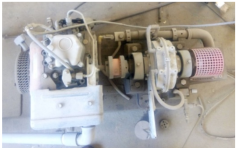
where, $\dot{Q}$ represents the heat loss $(\mathrm{kJ} / \mathrm{min}) ; m$ is the EG mass flow rate ($\mathrm{kg} / \mathrm{min}$); $C_p$ is the specific heat of EG $\left(\mathrm{kJ} / \mathrm{kg} \cdot{ }^{\circ} \mathrm{K}\right)$; and $\Delta T$ is the temperature gradient in ${ }^{\circ} \mathrm{K}$. Figure 1 shows the engine and dynamometer used in this study. The test is conducted at I.C. Engine Lab. at Al-Mustansiriya University, the details and specifications of engine and dynamometer are listed in Table 1.
Figure 1. Single cylinder C.I. engine with dynamometer
Table 1. C.I. engine and dynamometer specifications
|
Engine Specifications |
|
|
Engine |
Single Cylinder. Four-stroke, Compression ignition engine |
|
Bore |
87.5 mm |
|
Stroke |
110 mm |
|
Compression ratio |
17.5 |
|
Capacity |
661cc (0.661 L) |
|
Power |
8 hp (5.9 kW) at 1500 rpm |
|
Specific fuel consumption |
$220\ \mathrm{gms} / \mathrm{kW} \cdot \mathrm{h}(0.22 \mathrm{~kg} / \mathrm{kW} \cdot \mathrm{h})$ |
|
Pressure drop |
$\Delta P=120.2 \mathrm{~Pa}$ |
|
R.P.M. |
1500 rpm |
|
Cooling system |
Water cooled |
|
Specifications of Dynamometer |
|
|
The rope diameter |
25 mm |
|
The brake drum diameter |
255 mm |
|
Effective radius (R) |
R=[(255+25)⁄2]=140 mm |
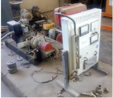
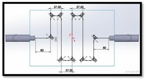
In this study, the engine exhaust pipe of a compression ignition engine is divided into two branches entering the multi-U-tube HX: one at the top and the other at the bottom of the cooking oven body. The U-tubes, which are placed instead of an electrical oven heater, were simulated (Figure 2(a) and (b)). The two branches of U-tubes are covered by two stainless steel plates to guarantee the best temperature distribution.
Figure 2. Sketching of the oven body and HX: (a) Oven body equipped with top and bottom HX, (b) Geometrical model of the multi-U-tube HX
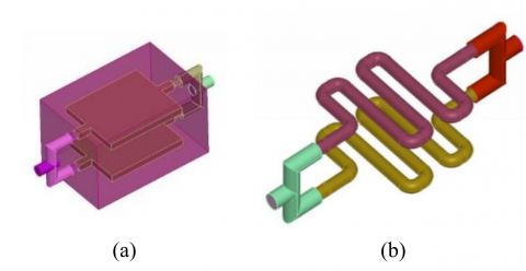
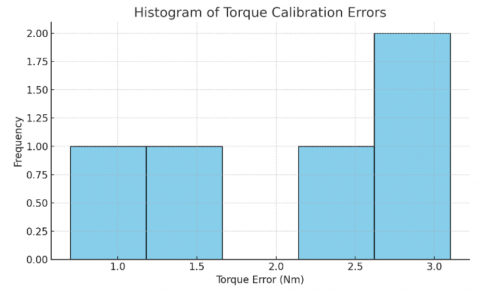
3.1 Dynamometer
The histogram shows the distribution of torque calibration errors. It visualizes how far off the dynamometer readings were from the actual torque values. Most of the errors are small, indicating decent calibration, but this kind of chart helps identify consistent bias or outliers, as shown in Figure 3.
Figure 3. Dynamometer calibration
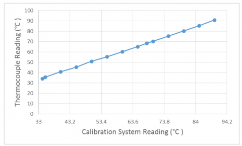
3.2 Temperature instrument
The calibration of the thermocouple is done in the heat transfer laboratory by comparing its readings with an already calibrated thermocouple of the same type (K) as shown in Figure 4. The figure shows that the error value is less than 0.25℃.
Figure 4. Sensor calibration
Heat is exchanged between HXs, which are powered by engine exhaust heat, and the oven environment. The body of the oven is already insulated to avoid losing heat to the surroundings. The engine’s available parameters are used as input parameters in a CFD by using ANSYS FLUENT version 15.0 to simulate the multi-U-tube HX model.
By comparison between the current study and the previous paper [2], the multi-U-tube HX presented high efficiency; therefore, we considered the multi-U-tube HX model in this study.
Several assumptions should be considered in the calculation of heat transfer in the multi-U-tube as the flow of working fluid inside the tube is incompressible, and the flow is steady state. The increase in pressure drop is a huge drawback in this type of HX. The pressure drop depends on the surface roughness, and it is a function of the roughness ratio and Reynolds number (Re). The roughness ratio represents the product of dividing the roughness by the tube diameter ($\varepsilon / d$). The Navier–Stokes equations of the 3D unsteady and incompressible flow are utilized for analysis.
$\nabla \cdot u=0$ (2)
$\rho\left(\frac{\partial u}{\partial t}+u \cdot \nabla u\right)=-\nabla p+\mu \nabla^2 u$ (3)
where, $u, \rho, p$, and $\mu$ are the velocity vector, fluid density, pressure and fluid viscosity, respectively. The boundary condition is considered no-slip at the wall of the tube. The flow rates of the fluid and given change are considered the inlet conditions. The ambient pressure is considered as outlet boundary condition. The shear stress transport (k-ω SST) turbulence model is utilized for the non-laminar concentration of 5% for the fluid flow [15]. The following equations are utilized for the computation of the tube dynamic structural [16]:
$-\tilde{C}: \nabla \cdot \tilde{\varepsilon}=f_V$ (4)
The matrix of elastic stiffness is expressed as follows:
$\tilde{C}=\frac{E}{(1+v)(1-2 v)}\left[\begin{array}{cccccc}1-v & v & v & 0 & 0 & 0 \\ v & 1-v & v & 0 & 0 & 0 \\ v & v & 1-v & 0 & 0 & 0 \\ 0 & 0 & 0 & 0.5-v & 0 & 0 \\ 0 & 0 & 0 & 0 & 0.5-v & 0 \\ 0 & 0 & 0 & 0 & 0 & 0.5-v\end{array}\right]$ (5)
where, $f_V$ is the rate of external force to the volume, which is incorporated as a result of the fluid pressure at the tube wall; $v$ and $E$ are Poisson’s ratio and Young’s modulus, respectively. In the current study, the Poisson’s ratio is recommended to be constant. Eq. (6) expressed the time rate of strain by considering the components of velocity for the tube elements.
$\frac{\partial \tilde{\varepsilon}}{\partial t}=\frac{1}{2}\left[(\nabla u)^T+\nabla u\right]$ (6)
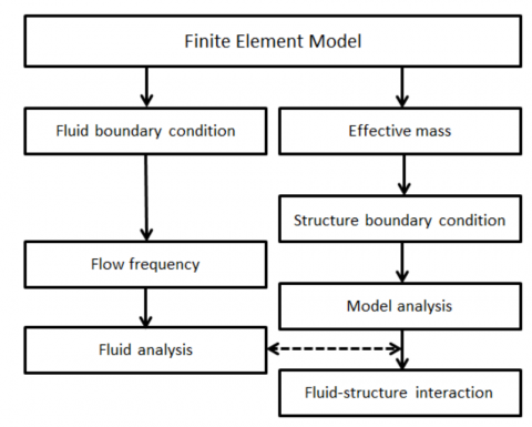
The velocity ingredient, especially on the right side in Eq. (6), can be computed depending on the structural distortion as a result of the strain field. Figure 5 is the computational methodology of the fluid structural interaction. The information on shape and node is utilized in the finite element model. The flow parameters are calculated, and then the mass is distributed to the tube to determine the external and internal fluid mass. After determining the data exchange between the working fluid and tube structure by nodal points, the system is coupled to both sides in each time step in Eq. (1) to Eq. (5) to describe the structural distortion.
Figure 5. Procedure of the multi-physical computation
One of the top providers of engineering simulation software, Ansys, provides a large selection of solution algorithms that are specific to different areas of physics. These algorithms are made to precisely and quickly address challenging engineering issues, rely on the Finite Element Method (FEM) in particular. Heat Transfer: Replicates radiation, convection, and conduction of heat. Solve the equations regulating mass, heat, and fluid movement in fluid dynamics.
Principle of mass and energy conservation-based model is illustrated:
$\frac{\partial \rho}{\partial t}+\frac{\partial(\rho . u)}{\partial x}+\frac{1}{r} \frac{\partial(\rho . v .)}{\partial r}=0$ (7)
Momentum equation:
$\frac{\partial(\rho \cdot u)}{\partial t}+\frac{\partial\left(\rho \cdot u^2\right)}{\partial x}+\frac{1}{r} \frac{\partial(\rho \cdot v \cdot r \cdot u)}{\partial r}=\frac{\partial}{\partial x}\left(\mu \cdot \frac{\partial u}{\partial x}\right)$ (8)
Energy equation:
$\frac{\partial(\rho . v)}{\partial t}+\frac{\partial(\rho . u .)}{\partial x}=\frac{\partial}{\partial x}\left(\frac{\partial u}{\partial x}\right)$ (9)
The correlations of roughness ratio ($\varepsilon / d$), Reynolds number (Re) and Darcy friction factor (f ) of a tube with straight line, the constant inner tube diameter as well as a cross-sectional shape are expressed as follows [17, 18]:
$\frac{1}{\sqrt{f}}=-2 \log _{10}\left(\frac{\varepsilon / d}{3.7}+\frac{2.51}{R e_d \sqrt{f}}\right)$ (10)
This expression is suitable for rigid pipes with no body vibration or wall distortion. The value of the friction factor can be estimated by changing the parameters by using ANSYS-FLUENT for numerical computation. The result is sensitive to the grid scale, especially the straight size of the grid ($\Delta y$) (Figure 6), which is expressed with a dimensionless parameter in Eq. (11).
Figure 6. Multi-U-tube details
$y^{+}=\Delta y \sqrt{\left.\frac{\rho d u_T}{\mu d y}\right|_{y=y_w}}$ (11)
where, $u_T$ is the velocity component of the tangential direction of the wall. The dimensionless wall distance should be less than one unit ($y<1$) in the whole calculation range to obtain the right values corresponding to Eq. (10). For example, 1,023,678 elements with tetrahedral type and a smooth wall at least $y \approx 0.3$ are present when the dimensions of the pipe are 2 m in length and 20 mm in diameter. The convergence should be examined during the calculation until the normalised error seems to be under the allowance value of 10-5.
In the simulation design, the exhaust flow in the HX fully guarantees that the turbulent flow and fluid viscosity can be careless. The standard κ-ε model is considered in the computational fluid dynamics simulation. The heat transfer coefficient in natural convection and the ambient temperature are set for the near wall area treatment with a standard tube wall function. The experimental test on the engine demonstrated that the ranges of pressure and temperature of EG were approximately 100-140 kPa and 250℃-400℃, respectively, when leaving the engine cylinder. The temperature of EG entering the multi-U-tube is set to 120℃. Based on the data collection from the engine operating condition, the inlet velocity (u) can reach 4.6 m/s. The coefficient of heat transfer between the external surface of the HX and the surrounding air is set to 23.6 W/m2. The ambient temperature is considered to be 20℃. The available parameters, such as ambient temperature, outlet EG velocity and temperature, are recorded with anemometers. A dimensionless equation applied to the smooth tubes with a velocity less than 5 m/s is used to determine the heat transfer coefficient (h) [19]:
$h=5.7+3.9(u)$ (12)
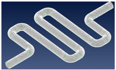
The multi-U-tube HE (Figure 7) represents the grid system generated through the meshing of the tetrahedral elements in the wall of the multi-U-tube. The accuracy of the CFD results is improved by utilizing unstructured grids in the area around the tubes and vortex generators. The quality of mesh evaluated in the current study, the evaluation involves the number, the number, the maximum aspect ratio, the maximum skewness and the minimum orthogonal quality of the cells. The study also depends on direction and size to identify the number of mesh elements. Generally, the orthogonal quality should be more than 0.1 and the maximum skewness recommended to be less than 0.95. However, these values depend on location and the number of cells that vary according to the shapes of the models. In the current study, the mesh elements (for multi-U-tube) were counted (2,290,981). The solution is considered converged when the scaled residuals of continuity, momentum and energy remain constant after approximately 144 successive iterations. The scaled residuals recorded minimum values after these iterations equate to 10-3 for the continuity equation and the velocity and laminar quantities, then for the energy equation values equate to 10-6.
Figure 7. Grids generated for the computation domain of the multi-U-tube
The performance of multi-U-tubes is listed in Table 2. We composed a standard full-scale model for the computation of fluid from the geometric data. In the classical theory, the pressure drop directly depends on the Darcy friction factor (f) (Eq. (13)) [14, 20].
$\Delta p=\rho \cdot g \cdot h_f=f \frac{L}{d}\left(\frac{1}{2} \rho \cdot u^2\right)$ (13)
where, $u=\|\mathbf{u}\|_2$ in the radial mean, and $L$ and $d$ are the length and diameter of the tube, respectively [18]. However, the extra pressure loss should take place at the bent angle of the tube.
Table 2. Performance of the multi-U-tube
|
Material Type |
Stainless Steel |
|
Tube size and tube surface roughness |
External diameter = 25.4 mm |
|
Thickness = 1 mm |
|
|
Length = 134 cm |
|
|
Pitch = 57.50 mm |
|
|
Surface roughness: inner 0.5 $\mu \mathrm{m}$ Ra, outer 1.6 $\mu \mathrm{m}$ Ra |
|
|
The shape of tube |
Multi-U-tube shape (bending radius R = 20 mm) |
|
The mechanical properties |
Density = 7897 kg/m3 |
|
Young’s-modulus is equal to 211 GPa |
|
|
Poisson’s-ratio is equal to 0.289 |
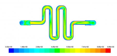
According to heat transfer correlation $Q=h \cdot A \cdot \Delta T$, the convection heat transfer can be enhanced by expanding the heat transfer surface area. To achieve this aim, the geometric structure should be changed to a multi-U-tube. According to the theories of fluid dynamics, the heat transfer coefficient (h) can be increased under the conditions of $R e>104$ and turbulent flow. Thermal resistance commonly occurs in the boundary layer due to the turbulent flow [21]. Therefore, this study considered adding a multi-U-tube as a turbulent system to increase the disturbance of fluid and damage the boundary layer. CFD software is utilized to simulate the flow of EG within the HX to present the temperature distribution. The inlet temperature and flow rate of EG of the HX were varied to estimate the result of perfect thermal field simulation. Therefore, the test is repeated three times with three different engine speeds, namely, 1000, 1500, and 2000 rpm. Figure 8 shows the velocity distributions inside a multi-U-tube. The maximum fluid velocity at the centre grows as a result of the boundary layer thickens with the increase in the curve and roughness. The mean value of fluid flow velocity is 5.4 m/s under the engine operating condition with 2000 rpm.
Figure 8. Velocity contour inside the multi-U-tube
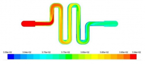
The 3D model of the multi-U-tube HXs is computed according to the above-mentioned turbulent flow and thermal convection theories. Figure 9 shows the CFD simulation results involving the temperature contour.
Figure 9. Temperature contour of the HX
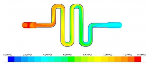
In Figure 10, the pressure distribution inside a fluid flow system is shown visually by the pressure contour plot. Different pressure levels are represented by the colors on the diagram; generally speaking, red denotes greater pressures and blue denotes lower pressures. We may infer some information about the pressure distribution from the colors and flow route shape:
Figure 10. Pressure contour of the HX
The type of material of HX is an important factor that can influence the thermal performance of the HX. The type of material not only influences the thermal conductivity but also controls the uniformity of thermal stress in the system [22]. Therefore, stainless steel is selected as the HX material in CFD simulation.
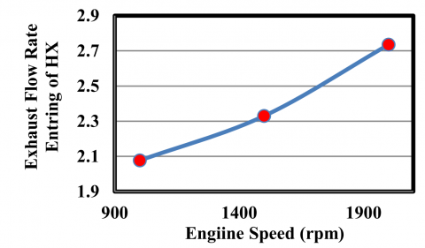
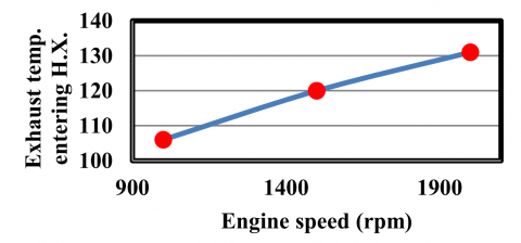
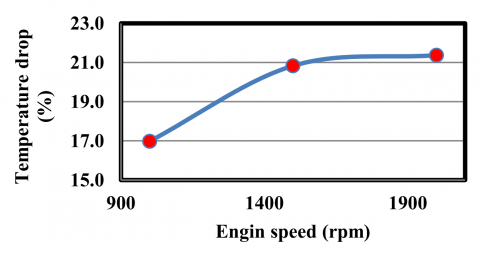
From simulation results, Figure 11 presents the change in the engine rotational speed with the different mass flow rates of EG. The mass flow rate of EG increased with the engine rotational speed, and its value range was 2.07 kg/s to 2.75 kg/s. The temperatures of the EG entering and exiting the multi-U-tube also increased with the increase in engine rotational speed (Figure 12). The increase in engine speed will increase with the EG flow rate, thereby leading to the enhancement of the heat transferred to the oven environment. The use of the multi-U-tube as an EG recovery device will lead to enhanced output power and diversion efficiency due to the large quantity of thermal energy obtained in the HE. Therefore, the simulation results indicate that the HX produces an increase in temperature drop of waste heat with a range from 17.5% to 21.4%, where the temperature drop increases with accelerating engine revolutions, as shown in Figure 13.
Figure 11. EG flow rate against the engine speed
Figure 12. EG temperature against the engine speed
Figure 13. HX temperature drop against engine speed
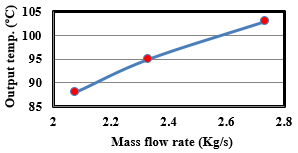
By increasing the engine rotational speed, the mass flow rate of EG increased with a range value from 2.07 kg/s to 2.75 kg/s. that means the heat exchanger received enough value of temperature to achieve cooking process. That explained the increase in the output temperature of EG against mass flow rate, where the increase in output temperatures seems approximately uniform Figure 14.
Figure 14. HX output temperature against EG mass flow rate
Although waste heat is considered a freely available source of energy, the diversion efficiency should be computed to evaluate the performance of HX. The waste heat recovery system's conversion efficiency can be determined by dividing the output power of HX by the total heat input to HX. The change in enthalpy of the EG across the HX is utilized as the input heat because of the difficulty of predicting the actual heat input to the HX:
$\eta=\frac{P_{ {output }}}{\dot{m} C_p\left(T_{ {out }}-T_{{in }}\right)}$ (14)
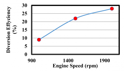
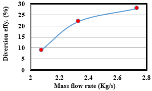
where, $\eta, P_{\text {output }}, \dot{m}, C_p, T_{\text {in }}$ and $T_{\text {out}}$ are the diversion efficiency, output power of the heat exchanger, flow rate by mass of the EG, heat specific of the EG, and the temperature of the EG system at inlet and outlet, respectively. Figure 15 shows that the range of diversion efficiency is 9%-28%. The maximum diversion efficiency of 28% occurs at 2000 rpm. The diversion efficiency is enhanced with an increase in the engine load and rotational speed. This factor could be enhanced by decreasing the loss of heat from the source to the oven surroundings through naked surfaces on the EG HX.
Figure 15. Engine speed with respect to diversion efficiency
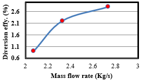
The increase in diversion efficiency is accelerated from zero to 2.7 Kg/s, and then this acceleration begins to decrease. The reason for this is the high temperature in the external environment of the heat exchanger, which leads to difficulty in transferring heat from the exchanger to the oven chamber, despite the insulation of the external walls of the oven Figure 16.
Figure 16. HX diversion efficiency against EG mass flow rate
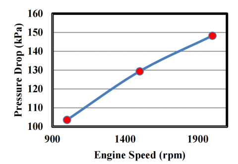
A multi-U-pipe was modelled to obtain the optimal design according to the CFD technique. A comparison was conducted between the CFD results and the Moody chart as validation to estimate the pressure drop. Heat transfer is coupled with pressure drop for a perfect HE, and the silencer leads the exhaust to a large pressure drop to reduce the noise. The fundamental reason for the increased pressure drop in the EG tube is because of the installation of HX would increase the fuel consumption, which will reduce the benefit of HE waste heat recovery. The multi-U-tube was modelled for an engine application to maintain the drop in pressure of the EG through HX below the level of several kilopascals. The pressure drop of EG through the HX increases with an increase in the engine load and rotational speed. However, the maximum pressure drop recorded for all numerical cases was 148.3 Pa (Figure 17).
Figure 17. Pressure drop across the HX against the engine rotational speed
The maximum increase in pressure drops across the multi-U-tube occurs at 1500 rpm by applying the multi-U-tube HX. This value increases approximately 11 Pa compared with the pressure drop in the engine without HX. The acceptable pressure drop in multi-U-Tube HX. depends on several criteria such as system specification, flow rate, type of fluid, and energy consideration, which are considered in this study. Therefore, the difference in pressure drop of 11 bar between the engine exhaust pipe with and without the heat exchanger is an acceptable difference [23, 24].
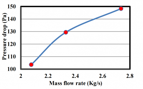
The increase in pressure drops firstly accelerates and then, and then this acceleration begins to decrease when engine speed reaches 2000 rpm and EG flow rate reaches 2.7 Kg/s. The reason for this is that when the engine reaches to uniform acceleration, the loads are reduced from the engine Figure 18.
Figure 18. Pressure drop across the EG mass flow rate
This study mainly aims to numerically examine the performance of waste heat recovery of an engine by using HX with a multi-U-tube shape to power an oven. The HX was modelled to have two branches: one on the top and the other on the bottom of the cooking oven. In this work, the multi-U-tube HX for recovering waste heat from an engine exhaust pipe is analyzed. A stainless steel HX with multi-U-tube shape and dimensions (25.4 mm by diameter, 1350 mm by length, 57.5 mm by pitch and 20 mm by curve diameter) is selected to obtain a higher surface heat transfer and uniform distribution of temperature to enhance the efficiency of the cooking oven according to the CFD simulation results. Numerical analysis was conducted for the internal design of the multi-U-tube to maximize the HE power output. The thermal performance of the HE was examined by using CFD ANSYS FLUENT. The CFD inlet parameters were predicted from the available parameters of a single-cylinder diesel engine for engine rotational speeds of 1000, 1500, and 2000 rpm. This study concentrates on the structural optimization of the HX to examine the heat transfer and pressure drop. The procedure to estimate the output power under all conditions of engine working was presented. Diversion efficiencies in the range 9%-28% were computed by utilizing the ratio of the HX output power to the change of thermal energy of the EG flow. The output power and diversion efficiency of the HX may be increased by decreasing the heat loss of EG to the environment. The back pressure through the HX was below 148.3 Pa under all conditions of engine working. A multi-physical simulation was carried out for the current problem to obtain the surface roughness of the inner tube and back pressure. The (ANSYS-FLUENT) code was considered to be a suitable grid level with empirical correlations, like a Moody-Chart. With the comprehension of the involved complex non-linear physics, the results of the current study can be utilized as reference data for the prediction of fluid structural interaction and the influence of back pressure as a result of the roughness of the inner surfaces of multi-U-tube systems in a HE powered by the gases. This situation leads us to adopt the design of HX in this study, which is used to operate the cooking oven and reduce the waste heat to the outside environment, where the simulation results indicate that the HX produce increase in temperature drop of waste heat with a range from 17.5% to 21.4%, the temperature drop increase with accelerating engine revolutions. It suggested future work includes experimental prototyping, transient flow analysis, integration with energy storage systems, and alternative heat exchanger geometries.
|
PCM |
phase change material |
|
CIE |
compression-ignition engine |
|
T |
temperature, ℃ |
|
EG |
exhaust gas |
|
HX |
heat exchanger |
|
CFD |
computational fluid dynamics |
[1] Abdulhamed, A.J., Rasheed, M.H., Kareem, H.K., Mariah, N., Ab-kadir, M.Z.A., Hairuddin, A.A. (2020). Design and performance testing of a parabolic trough collector including deformation test of the receiver tube. Journal of Advanced Research in Fluid Mechanics and Thermal Sciences, 67(2): 47-65.
[2] Abdulhamed, A.J., Aboud, E.D., Abdulameer, S.A., Kareem, H.K. (2022). Numerical analysis of cooking oven powered by engine exhaust gas. Journal of Engineering Science and Technology, 17: 50-59.
[3] Abdulhamed, A.J., Al-Akam, A., Abduljabbar, A.A., Alkhafaji, M.H. (2023). Waste heat recovery from a drier receiver of an a/c unit using thermoelectric generators. Energy Engineering, 120(8): 1729-1746. https://doi.org/10.32604/ee.2023.029069
[4] Sathiamurthi, P., Srinivasan, P.S.S. (2011). Design and development of waste heat recovery system for air conditioning, unit. Journal of Scientific Research, 54: 102-110.
[5] Gürbüz, H., Aytaç, H.E., Akçay, H., Cahit Hamamcıoğlu, H. (2022). Improvement of volume controlled thermal energy storage system using phase change material for exhaust waste heat recovery in a SI engine. Journal of Energy Storage, 53: 105107. https://doi.org/10.1016/j.est.2022.105107
[6] Çakmak, G. (2013). Experimental investigation of thermal storage in U-tube heat exchanger. International Communications in Heat and Mass Transfer, 44: 83-86. https://doi.org/10.1016/j.icheatmasstransfer.2013.03.012
[7] Li, X.L., Tong, C., Duanmu, L., Liu, L.K. (2017). Study of a U-tube heat exchanger using a shape-stabilized phase change backfill material. Science and Technology for the Built Environment, 23(3): 430-440. https://doi.org/10.1080/23744731.2016.1243409
[8] Ma, W.M., Karbojian, A., Sehgal, B.R., Dinh, T.N. (2009). Thermal-hydraulic performance of heavy liquid metal in straight-tube and U-tube heat exchangers. Nuclear Engineering and Design, 239(7): 1323-1330. https://doi.org/10.1016/j.nucengdes.2009.03.014
[9] Weng, C.C., Huang, M.J. (2013). A simulation study of automotive waste heat recovery using a thermoelectric power generator. International Journal of Thermal Sciences, 71: 302-309. https://doi.org/10.1016/j.ijthermalsci.2013.04.008
[10] Gürbüz, H., Akçay, H., Topalcı, Ü. (2022). Experimental investigation of a novel thermoelectric generator design for exhaust waste heat recovery in a gas-fueled SI engine. Applied Thermal Engineering, 216: 119122. https://doi.org/10.1016/j.applthermaleng.2022.119122
[11] Gürbüz, H., Akçay, H. (2023). Development of an integrated waste heat recovery system consisting of a thermoelectric generator and thermal energy storage for a propane fueled SI engine. Energy, 282: 128865. https://doi.org/10.1016/j.energy.2023.128865
[12] Yu, C., Chau, K.T. (2009). Thermoelectric automotive waste heat energy recovery using maximum power point tracking. Energy Conversion and Management, 50(6): 1506-1512. https://doi.org/10.1016/j.enconman.2009.02.015
[13] Mori, M., Yamagami, T., Oda, N., Hattori, M., Sorazawa, M., Haraguchi, T. (2009). Current possibilities of thermoelectric technology relative to fuel economy. SAE Technical Paper 2009-01-0170. https://doi.org/10.4271/2009-01-0170
[14] Abduhamed, A.J., Adam, N.M., Hairuddin, A.A., Kareem, H.K. (2016). Design and fabrication of a heat exchanger for portable solar water distiller system. International Food Research Journal, 23: 15-22.
[15] Menter, F.R. (1994). Two-equation eddy-viscosity turbulence models for engineering applications. AIAA Journal, 32(8): 1598-1605. https://doi.org/10.2514/3.12149
[16] Ahmad, A., Anagnostopoulos, A., Navarro, M.E., Maksum, Y., Sharma, S., Ding, Y. (2024). A comprehensive material and experimental investigation of a packed bed latent heat storage system based on waste foundry sand. Energy, 294: 130920. https://doi.org/10.1016/j.energy.2024.130920
[17] Ihsan Shahid, M., Rao, A., Farhan, M., Liu, Y., Ma, F. (2024). Comparative analysis of different heat transfer models, energy and exergy analysis for hydrogen-enriched internal combustion engine under different operation conditions. Applied Thermal Engineering, 247: 123004. https://doi.org/10.1016/j.applthermaleng.2024.123004
[18] White, F.M. (1999). Fluid Mechanics. WCB/McGraw-Hill. https://www.google.bg/books/edition/Fluid_Mechanics/fa_pAAAAMAAJ?hl=en&gbpv=0&bsq=inauthor:%22Frank%20M.%20White%22.
[19] Rahman Ahmed, A., Usman, M., Arshad, H., Faizan, M., Wajid Saleem, M., Fouad, Y., Abbas, N., Sajjad, U., Hamid, K. (2024). Thermal analysis of cooling plate motor jacket and radiator for managing an electric bike energy storage system. Energy Conversion and Management: X, 23: 100670. https://doi.org/10.1016/j.ecmx.2024.100670
[20] Alkhakani, A.J., Adam, N.M., Hairuddin, A.A., Kadhim, H.H. (2015). Effect of tube thickness for shell and tube heat exchanger in portable solar water distiller. International Journal of Engineering Research & Technology, 4: 37-42.
[21] Guo, Z.Y., Tao, W.Q., Shah, R.K. (2005). The field synergy (coordination) principle and its applications in enhancing single phase convective heat transfer. International Journal of Heat and Mass Transfer, 48(9): 1797-1807. https://doi.org/10.1016/j.ijheatmasstransfer.2004.11.007
[22] Lu, H.L., Wu, T., Bai, S.Q., Xu, K.C., Huang, Y.J., Gao, W.M., Yin, X.L., Chen, L.D. (2013). Experiment on thermal uniformity and pressure drop of exhaust heat exchanger for automotive thermoelectric generator. Energy, 54: 372-377. https://doi.org/10.1016/j.energy.2013.02.067
[23] Mandal, M.M., Nigam, K.D.P. (2009). Experimental study on pressure drop and heat transfer of turbulent flow in tube in tube helical heat exchanger. Industrial & Engineering Chemistry Research, 48(20): 9318-9324. https://doi.org/10.1021/ie9002393
[24] Aslam Bhutta, M.M., Hayat, N., Bashir, M.H., Khan, A.R., Ahmad, K.N., Khan, S. (2012). CFD applications in various heat exchangers design: A review. Applied Thermal Engineering, 32: 1-12. https://doi.org/10.1016/j.applthermaleng.2011.09.001