Olamide O. Ajayi* | Stella I. Monye | Adedotun O. Adetunla | Imhade P. Okokpujie | Ngozi S. Monye | Chan Choon Kit
© 2025 The authors. This article is published by IIETA and is licensed under the CC BY 4.0 license (http://creativecommons.org/licenses/by/4.0/).
OPEN ACCESS
This study presents a novel method for energy harvesting in wearable devices through the development of smart footwear that generates and monitors sustainable energy from human motion. The system integrates piezoelectric sensors, a microcontroller, a rechargeable battery, and a boost converter. Mechanical vibrations from walking are captured by sensors in the sole and converted into electrical energy, which is stored in the battery. A monitoring system embedded in the ankle brace tracks real-time energy generation and consumption. Experimental results indicate that the footwear produces sufficient power for low-energy applications, with energy output directly proportional to foot traffic. The mechanical-to-electrical conversion efficiency is 4.44%, and the monitoring system operates at 0.716 W. The battery charges from 3.6 V to 4.2 V in approximately 2.7 hours, with a recommended charging limit of 90% to extend the battery lifespan. This design promotes sustainable energy use in wearables and offers a practical foundation for optimizing energy harvesting in future technologies.
energy efficiency, energy conversion, mechatronics, piezoelectric systems, sensors, vibration
Research on energy harvesting for wearable or body-mounted applications has garnered considerable attention due to its potential to power contemporary low-energy sensor systems and enhance user mobility and autonomy. Previous studies have indicated that human gait generates several dozen Watts of energy, making it a viable source for harvesting energy from human movement, which will be the primary focus of this work [1]. Currently, the utilization of human motion for energy harvesting stands as a convenient and promising approach to continuously power wearable electronic devices. It has been explored to convert mechanical energy generated by human activity into electrical energy [2-6]. Among these, shoes, being an essential part of daily life, have garnered significant attention from researchers as an energy-harvesting platform. The concept of charging electronic devices through shoes has gained traction due to the substantial energy generated during walking, making shoe-based energy harvesting a relatively simple and effective approach.
Globally, fossil fuels constituted 83% of total energy consumption in 2020, with this reliance contributing to 78% of the increase in greenhouse gas emissions from 1970 to 2011 [7, 8]. Daily actions like phone charging, seemingly insignificant, collectively demand substantial energy, as evidenced by the fact that 70% of the global population was using mobile phones in 2015, estimated to reach 5.645 billion by 2020 [9]. Charging phones daily on this scale results in an annual consumption of 10,300 gigawatt-hours, a significant portion of which comes from fossil fuels, contributing to environmental pollution and climate change. At its core, energy harvesting refers to the process of transforming unused energy found in our surroundings into electrical energy that can be utilized right away or stored for future use. This expansive definition encompasses various applications, heavily influenced by the scale of the energy being harvested. Large sources, such as vehicle suspension systems, skyscrapers, or ocean waves, can generate power levels reaching tens of kilowatts, presenting opportunities for renewable energy [10]. Some researchers have noted that energy extraction from vibrations can occur through the movement of a spring-mounted mass in relation to its supporting frame [11, 12].
According to Wen et al. [13], mechanical acceleration is generated by vibrations that cause the mass component to shift and oscillate. This relative movement encounters opposing frictional and damping forces acting on the mass; the oscillations are finally reduced to zero. This study seeks to tackle this challenge by introducing an innovative, sustainable power generation method for low-energy tasks like phone charging and lighting. By reducing reliance on fossil fuels for these essential activities, the aim is to mitigate environmental impact and effectively combat climate change.
The aim of this study is to develop smart energy harvesting footwear for sustainable power generation and safety. To address these challenges, this study will involve embedding piezoelectric sensors into shoe soles to capture energy from walking or running, which will be converted into electrical power. This study seeks to harness recent advances in flexible piezoelectric materials to explore the feasibility of energy harvesting from shoes. The methodology and the results will be discussed extensively.
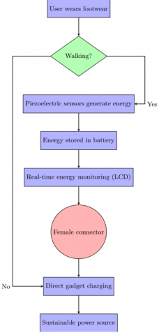
The design consideration for the study is factored around the limitations it’s focused on improving; these major factors are design simplicity, cost effectiveness, user comfort, and energy harvesting, storage, and monitoring. Figure 1 shows the system workflow.
Figure 1. System workflow
2.1 Materials selection and design analysis
2.1.1 Shoes
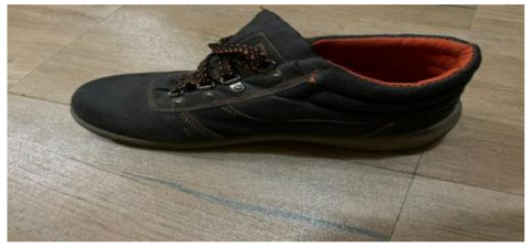
The Rock lander safety boots, designed for durability in tough work environments, are made from strong materials like leather, as shown in Figure 2. They offer protection against impacts, compression, punctures, and electrical hazards, making them ideal for hikers. These boots are robust, capable of handling heavy loads and pressures in rugged terrain or industrial settings. They feature slip-proof, oil-resistant, crush-proof, and pierce-proof properties, including a compression rating typically measured in pounds (lbs) or kilonewtons (kN), commonly rated at 75 lbs (34 kg) or 50 kN.
Figure 2. The shoe
2.1.2 The piezoelectric transducers and diodes
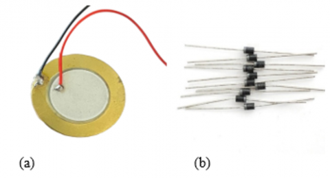
The piezoelectric transducer is the heart of the harvesting robot, and it is responsible for sensing, converting vibration in steps to electrical energy, and harvesting it [14, 15]. The buzz35P module used in this study is precise, reliable, and durable, as shown in Figure 3(a). While the diode in this study serves to rectify the AC voltage from piezoelectric transducers into a DC voltage, ideal for energy storage and utilization. Additionally, they are crucial in the Wheatstone bridge circuit, where they rectify the electrical signal generated upon pressure or deformation, enhancing the energy output as shown in Figure 3(b).
Figure 3. (a) Piezoelectric transducer, (b) Diodes
2.1.3 Mechanism of piezoelectric energy transformation
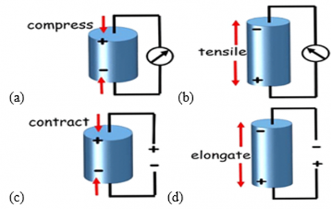
Materials made of Piezoelectric are characterized by their capacity to undergo mechanical deformation when exposed to an electric field or generate electrical charges under mechanical stress. When these materials are subjected to mechanical strain, they emit an electric charge—a phenomenon known as the direct piezoelectric effect, as illustrated in Figures 4(a) and 4(b).
Figure 4. Schematic of direct piezoelectric effect (a) compressive force, (b) tensile, (c) contraction, (d) elongation [16]
Conversely, the inverse piezoelectric effect is observed when the application of an electric field induces mechanical deformation in the material, as depicted in Figures 4(c) and 4(d). Typically, piezoelectric materials exhibit a non-centrosymmetric crystal structure. Upon the application of external mechanical force, the positive and negative charge centers within the material become displaced, creating an electric dipole moment.
The piezoelectric constitutive Eqs. (1) and (2) represent the direct and inverse piezoelectric effects, respectively, as described [17]:
$x=s^E X+d E$ (1)
$D=d X+\varepsilon^X \varepsilon_0 E$ (2)
where,
x = Mechanical strain
X = Mechanical stress
sE = Compliance at constant electric field
d = Piezoelectric coefficient
E = Electric field
D = Electric displacement
εᵡ = Relative permittivity at constant stress
ε₀ = Vacuum permittivity
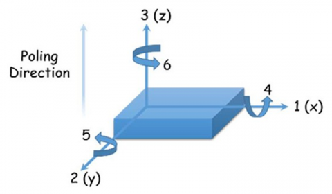
In Figure 5, the axes "1," "2," and "3" represent the x, y, and z directions, respectively, while "4," "5," and "6" correspond to shear planes perpendicular to those axes. The piezoelectric charge coefficient dᵪᵧ quantifies the electric charge generated per unit area under applied mechanical stress (C/N), with x and y indicating the polarization and stress directions. Piezoelectric materials possess a polar axis based on crystal orientation or poling direction, the "3" direction represents the polar axis, while the "1" direction is perpendicular. When stress is applied along the polar axis, it is termed 33-mode (longitudinal), and when applied perpendicular, it is 31-mode (transverse). Typically, d₃₃ is greater than d₃₁.
Figure 5. Diagram of a piezoelectric transducer with associated tensor orientations for defining constitutive relationships [18]
Expressed in volts per newton (V/N), the piezoelectric voltage coefficient (gᵪᵧ) quantifies the ratio of the induced electric field to the applied mechanical stress, with x and y indicating the directions of the electric field and the mechanical load, respectively. Furthermore, it can be understood as the strain generated in the y-axis for each unit of electric displacement applied along the x-axis. Similar to the electrical equation V = Q/C—where V is voltage, Q is charge, and C is capacitance—the relationship between dᵪᵧ and gᵪᵧ follows an analogous pattern. This implies that an increase in dᵪᵧ is often accompanied by a rise in the dielectric constant if gᵪᵧ remains constant.
$g_{x y}=\frac{d_{x y}}{\varepsilon_{x y}^T \varepsilon_0}$
where,
gᵪᵧ = Piezoelectric voltage coefficient in the xy direction (V·m/N)
dᵪᵧ = Piezoelectric charge coefficient (C/N)
εᵪᵧᵀ = Dielectric constant
ε₀ = Permittivity of free space (8.854×10⁻¹² F/m)
The electromechanical coupling factor (kᵪᵧ) measures the efficiency of energy conversion between mechanical and electrical forms in a piezoelectric material. Here, x represents the electrode application direction, while y indicates the direction of applied or generated mechanical energy.
2.1.4 Battery and power bank module
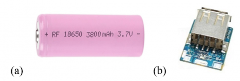
The 3800 mAh capacity of the LiPo battery indicates the total amount of charge it can store. When the module is used to charge a device, it can deliver up to 1.2 A of current (to the module), which will deplete the battery’s charge over time, as shown in Figure 6(a). If a device draws the full 1.2 A, the 3800 mAh battery would theoretically last for about 3.17 hours before needing a recharge, calculated as 3800 mAh/1200 mAh [19]. The power bank module acts as a voltage converter, as shown in Figure 6(b). The T6845C accepts a 5 V DC charging voltage and can output 5 V DC through the USB port, with an output current of 1200 mA (1.2 A).
Figure 6. (a) Battery, (b) Power bank charging module (T6845C)
2.1.5 Energy monitoring system
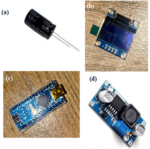
A 100 microfarad 50 V Capacitor was used to store the charge and filter the signal for a smoother, direct current, as shown in Figure 7(a). The 0.96-inch OLED display module is compact and versatile, as shown in Figure 7(b) is widely used in electronics. It features a 128 × 64 pixel resolution for crisp visuals, typically monochrome with some colour options available. Using the I2 C protocol, it integrates easily with microcontrollers like Arduino and ESP8266 via SDA and SCL data lines. Powered by the SSD1306 driver IC, the setup is simplified with Arduino libraries. It operates within a broad voltage range of 3 V to 5 V, supporting both 3.3 V and 5 V logic levels. Another key component is the Arduino Nano microcontroller, which is based on the ATmega328P as shown in Figure 7(c). It is a compact and versatile board that replicates the connectivity and specifications of the Arduino UNO in a smaller size. It uses the Arduino Software (IDE), providing a familiar programming environment. Power can be supplied via Mini-B USB or external sources ranging from 6 V to 20V (unregulated) or 5V (regulated), offering flexible power options. Featuring the ATmega328 with 32 KB flash memory, 2 KB SRAM, and 1 KB EEPROM, the Nano provides ample resources for various projects. Its 14 digital pins serve as versatile inputs or outputs, enhancing adaptability. Lastly, a boost converter was used to increase the 3.7 V from the battery to 5.0 volts to be supplied to the Arduino in the monitoring system, to power it up as shown in Figure 7(d).
Figure 7. (a) Capacitor, (b) OLED display, (c) Arduino nano, (d) Boost converter module
2.2 Experimental setup
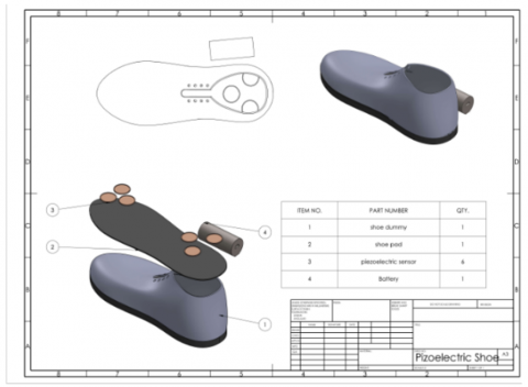
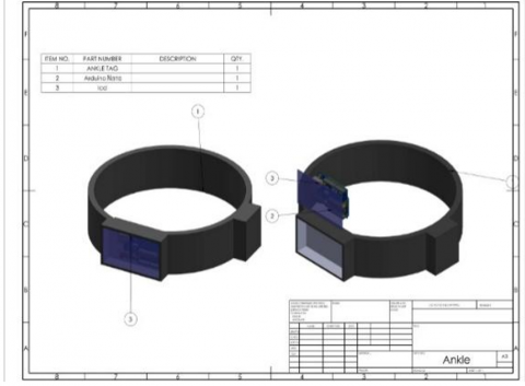
The experimental procedures that were undertaken in the development of this project were tailored towards the development of the most effective and cost-efficient prototype for a piezoelectric energy harvesting footwear for energy monitoring and safety. The design included the selection of the appropriate components. The piezoelectric footwear is, by design, divided into 2 main sections, which are the piezoelectric footwear itself and the energy monitoring system. The 3D design of the piezoelectric footwear is shown in Figure 8(a), while the energy monitoring system is shown in Figure 8(b).
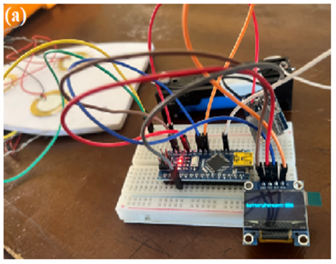
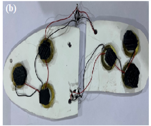
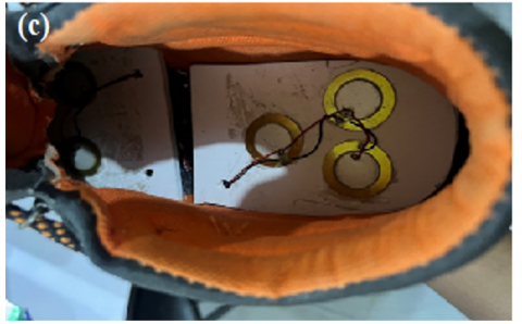
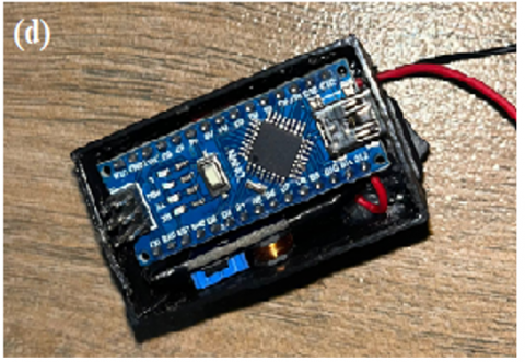
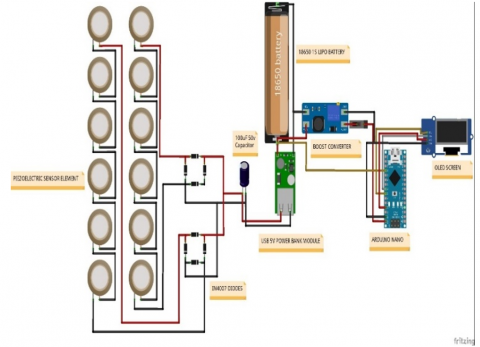
Assembling the piezoelectric energy harvesting footwear involves integrating components into a functional system. Components like microcontroller, battery, boost converter, piezoelectric sensors, capacitor, diodes, charge module, OLED, switch, and footwear are gathered. The footwear frame and controller are constructed, shaping the sole for sensors and the monitoring system case. Parts are securely fitted with adhesive. The Arduino Uno microcontroller, OLED, switch, and boost converter provide voltage. Piezoelectric sensors convert vibrations to electrical energy, mounted on the sole and connected to the battery and Arduino Nano. Electronics assembly connects piezoelectric sensors in parallel. Their output passes through a diode in a full-wave rectifier, then to the charge controller input, and the boost converter outputs 6.5 V. This connects to Arduino's Vin and GND pins, with the battery powering Arduino's positive and ground pins (Ao). OLED pins connect to Arduino Nano, with libraries monitoring battery voltage and displaying percentage as shown in Figures 9(a)-(d).
Figure 9. Assembly of piezoelectric footwear (a) Electronic connection, (b) Electronic connection of sensors in parallel, (c) Incorporation into footwear, (d) Energy monitoring system
Figure 10. Circuit diagram
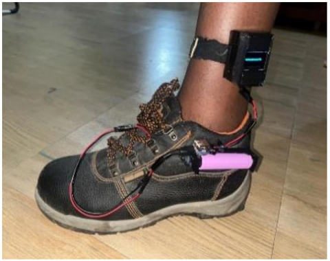
Figure 10 depicts the circuit diagram, which shows the electrical connections of all components, whereas the final assembly of the piezoelectric footwear is shown in Figure 11. A PVC sheet was cut to fit the sole of the footwear, serving as the base for sensor placement. Circular foams were positioned over the sensor centres to concentrate force on the most impacted areas. Additionally, the battery and charging module were affixed to the side of the footwear for convenient access and integration. The piezoelectric harvesting footwear operates seamlessly as the user wears it, harnessing energy through the piezoelectric sensors embedded within the sole with each step taken. The pressure applied to these sensors while walking or movement produces electrical energy from mechanical tension, which is then stored in a rechargeable battery built into the shoe. An LCD screen coupled with a microprocessor attached to an ankle brace allows for real-time monitoring of the captured energy, giving users insight into the power produced. Furthermore, the shoes have a female connector that allows devices like smartwatches and cell phones to be directly charged while they are in motion.
Figure 11. The piezoelectric energy harvesting footwear
2.3 Wearability and long-term durability tests
The prototype was integrated into a rugged hiking boot for structural support, but a lighter, more flexible sneaker is recommended for comfort and versatility. Testing revealed insufficient sole cushioning, leading to sensor damage from direct impacts. Adding cushioning layers and using more durable piezoelectric elements would enhance longevity and reliability. As shown in Figure 11, wiring was externally routed due to off-the-shelf shoe limitations; future designs could embed wiring for better protection, aesthetics, and comfort.
Some experimental analyses were carried out to determine the foot traffic, power output from the sensors, efficiency of the conversion from mechanical to electrical, electrical power generated, time, and number of steps required to charge the battery from one point to another for the tested user of 76 kg weight.
3.1 Efficiency analysis of the power-generating system
Table 1 presents the data generated from a physical test of the developed energy-generating footwear. The footwear was used for a total of 2hr: 40mins, which accounts for 3240 steps, and a total voltage of 4.2 volts was generated. Hikers, long-distance athletes, or those who take long walks would be able to achieve 100% energy conservation. To calculate the efficiency of the power-generating system, the mechanical power input into the sensors' connection and the electrical power output from the sensors' connection are recorded.
Taking time = 1s
Mechanical Power = Mechanical Energy/ time
Mechanical Power = 4.5 / 1
Mechanical Power = 4.5 Watts
Electrical Power = Voltage × Current
The Output Voltage from the piezoelectric sensors’ connection in a step, in one second, was measured to be 10 V, and the current was 0.02 A before connecting to the power bank module and then to the battery.
Electrical Power = 10 × 0.02
Electrical Power = 0.2 Watts
Efficiency = (Power Output/Power Input) × 100
Efficiency = 4.44%
A 4.44% efficiency was achieved with a 76 kg user walking at 2.52 km/h. Similarly, a previous study reported 4.7% efficiency for an 84 kg user at 4.8 km/h [14]. Despite lower body weight and speed, the efficiency was comparable, indicating that design and environmental factors may influence performance more than user characteristics. Enhancing efficiency could involve optimizing pressure transmission to piezoelectric elements using advanced cushioning (e.g., layered or viscoelastic foams), integrating higher-sensitivity sensors, employing multi-layered arrays, and ensuring electrical impedance matching to reduce energy loss.
Table 1. Data generated from experiments
|
Time (hr) |
Voltage (V) |
Steps |
Current (A) |
Voltage Increase |
Frequency of Footsteps/Time (steps/hour) |
Energy Storage Level (%) |
|
0 |
3.6 |
0 |
0 |
0 |
0 |
73 |
|
0.3 |
3.76 |
360 |
0.02 |
0.16 |
1200 |
80 |
|
0.5 |
3.86 |
620 |
0.02 |
0.1 |
1240 |
85 |
|
0.7 |
3.91 |
900 |
0.02 |
0.05 |
1286 |
87 |
|
1 |
3.95 |
1210 |
0.02 |
0.04 |
1210 |
89 |
|
1.2 |
3.96 |
1440 |
0.02 |
0.01 |
1200 |
89 |
|
1.5 |
3.99 |
1815 |
0.02 |
0.03 |
1210 |
90 |
|
1.8 |
4.04 |
2165 |
0.02 |
0.05 |
1203 |
93 |
|
2 |
4.08 |
2500 |
0.02 |
0.04 |
1250 |
95 |
|
2.3 |
4.15 |
2771 |
0.02 |
0.07 |
1205 |
98 |
|
2.5 |
4.2 |
3080 |
0.02 |
0.05 |
1232 |
100 |
|
2.7 |
4.2 |
3240 |
0.02 |
0 |
1200 |
100 |
3.2 Performance analysis of the developed footwear
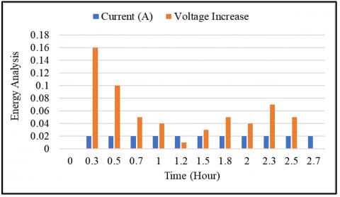
Figure 12 presents the relationship between voltage output and with duration of use of the footwear. This graph demonstrates the voltage generated by the piezoelectric material over time as a result of foot pressure. It shows the variation in electrical power generation and helps in assessing the system's performance under different conditions. The voltage increases fastest from 3.6 to 3.86 V, within the first 30 minutes of walking, for the data readings taken. Charging then slows down and briefly picks up toward the end of the charge cycle, which is a normal occurrence seen with a Lithium Polymer Battery [20].
Figure 12. Relationship between voltage output and time
3.3 Foot traffic analysis
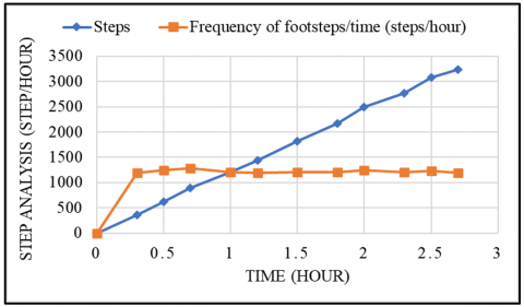
Figure 13 shows the variation in foot traffic over time, illustrating periods of high and low activity. It helps in understanding when the energy harvesting system can expect to generate the most power. The principle behind the use of piezoelectric sensors to harvest energy in footwear is in the fact that it converts mechanical vibrations to alternating current, which can be converted to DC and utilized. To calculate the amount of mechanical energy that is being harvested, the amount of force exerted on the sensors in a step is calculated. According to Khodaparastan et al. [21], Ground Reaction Force (GRF) serves as the primary source of excitation for harvesting kinetic energy during human walking. Studies indicate that the vertical ground reaction force varies between 1.1 and 1.3 times the individual's body weight (BW), depending on the walking speed. Therefore, the force exerted by a person’s footstep, which in this case is a 76kg person, taking GRF to be 1.2.
Force = Weight x GRF
Force= 76 × 1.2
Force= 91.2 N
While the mechanical energy available for harvesting from the foot traffic, in this case, for an insole displacement of 0.05m.
Mechanical Energy = Force × Displacement
Mechanical Energy= 91.2 × 0.05
Mechanical Energy = 4.5 Joules
Figure 13. The frequency of footsteps taken over time
3.4 Battery efficiency and cycle management
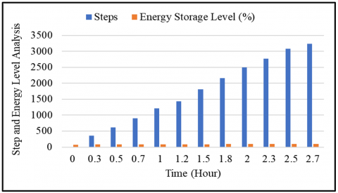
Figure 14 illustrates the performance of the battery monitoring system over time, showing how battery percentage is relayed to the user. The system is calibrated to interpret a 2.0 V reading as 0% and a 4.2 V reading as 100%. Experimental results indicate that voltage levels between 3.6 V and 4.2 V correspond to 73% and 100% charge, respectively. To extend battery lifespan and prevent overcharging, it is recommended not to exceed 90% charge. The cycle life of lithium-ion batteries, including LiPo cells, is largely influenced by charge-discharge protocols, specifically the maximum charge voltage and depth of discharge. Capacity degradation is primarily due to side reactions at the anode/electrolyte interface, causing SEI layer growth and increased resistance. Limiting the charge voltage to 4.0 V instead of 4.2 V significantly slows these reactions, enhancing the battery's lifespan. Experimental evidence shows that this approach enables nearly 2000 cycles with minimal capacity loss. In the current prototype, a manual disconnect at 90% charge is used via a male-female connector, while future iterations could automate this process for greater efficiency and user convenience.
Figure 14. Energy storage level with time
3.5 Statistical analysis of the relationship between steps and voltage
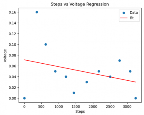
Figure 15 shows how the voltage changes as the steps increase. Statistical analysis revealed a weak negative correlation between the number of steps and the voltage generated (Pearson r = -0.31). Linear regression analysis showed that steps are not a strong predictor of voltage (Voltage = -0.00 × Steps + 0.07), with an R² value of 0.10. This suggests that step count alone does not significantly influence the voltage output, indicating the presence of other contributing factors.
Figure 15. Voltage against steps
In this study, the piezoelectric energy harvesting footwear for sustainable power generation and monitoring has been explored, examining its potential to improve energy harvesting techniques by providing a means of harnessing the mechanical energy expended in walking and converting it to useful electrical energy. A detailed examination of the key components and functionalities of the footwear, such as the monitoring system, boost converter, power bank charging module, OLED screen, Arduino nano, and piezoelectric sensors, has been presented. The integration of these components allows the footwear to generate voltage to sufficiently charge the battery and allows the user to monitor the battery life. The following conclusions are deduced as follows:
•The results show the footwear generates sufficient power for low-energy devices, with energy output correlating directly to foot traffic. Conversion efficiency from mechanical to electrical energy is 4.44%, and the monitoring system manages power consumption at 0.716 W.
•The battery charges from 3.6 V to 4.2 V in approximately 2.7 hours, with recommended charging up to 90% for extended lifespan.
Users may power their devices conveniently without requiring additional power sources thanks to its integrated charging technology, which improves mobility and use. As the user goes about their daily business, energy is continuously harvested, guaranteeing a reliable and effective power source for demands related to on-the-go charging.
The authors acknowledge Afe Babalola University, Nigeria and INTI International University, Malaysia for the joint research and experimental validation. The research is supported by INTI Seed Grant (INTI-FEQS-01-13-2023).
[1] Ylli, K., Hoffmann, D., Folkmer, B., Manoli, Y. (2013). Design, fabrication and characterization of an inductive human motion energy harvester for application in shoes. Journal of Physics: Conference Series, 476(1): 012012. https://doi.org/10.1088/1742-6596/476/1/012012
[2] Ylli, K., Hoffmann, D., Willmann, A., Folkmer, B., Manoli, Y. (2015). Investigation of pendulum structures for rotational energy harvesting from human motion. Journal of Physics: Conference Series, 660(1): 012053. https://doi.org/10.1088/1742-6596/660/1/012053
[3] Ylli, K., Hoffmann, D., Willmann, A., Manoli, Y. (2018). Development of a miniature water turbine powered by human weight during walking. Journal of Physics: Conference Series, 1052(1): 012085. https://doi.org/10.1088/1742-6596/1052/1/012085
[4] Ylli, K., Hoffmann, D., Becker, P., Willmann, A., Folkmer, B., Manoli, Y. (2014). Human motion energy harvesting for AAL applications. Journal of Physics: Conference Series, 557(1): 012024. https://doi.org/10.1088/1742-6596/557/1/012024
[5] Zhu, D. (2011). Vibration energy harvesting: machinery vibration, human movement and flow induced vibration. Sustainable Energy Harvesting Technologies-Past, Present and Future, 1: 22-54. https://doi.org/10.5772/25731
[6] Gokulraj, K., Prakash, S., Ragunanthan, G., Keerthivasan, D., Abikumar, M. (2023). Micro power generation using piezoelectric transducer in footwear. International Journal of Research - Granthaalayah, 11(4): 103-109. https://doi.org/10.29121/granthaalayah.v11.i4.2023.5154
[7] Saeng-On, P., Thaitae, N., Sonasang, S. (2023). Development of monitoring PM2.5 based on IoT and Google Data Studio. In 2023 International Electrical Engineering Congress (iEECON), Krabi, Thailand, pp. 64-67. https://doi.org/10.1109/iEECON56657.2023.10126631
[8] Gogoi, N., Fischer, G. (2023). A comparative study of different types of piezoelectric interface circuits to perform simultaneous sensing and energy harvesting. IEEE TechRxiv. https://doi.org/10.36227/techrxiv.21972242.v1
[9] Gadzama, W., Joseph, B., Aduwamai, N. (2019). Global smartphone ownership, internet usage and their impacts on humans. Reseachjournali’s Journal of Communications Networks, 1(1): 1-10.
[10] Aabid, A., Raheman, M.A., Ibrahim, Y.E., Anjum, A., et al. (2021). A systematic review of piezoelectric materials and energy harvesters for industrial applications. Sensors, 21(12): 4145. https://doi.org/10.3390/s21124145
[11] Fang, L.H., Hassan, S.I.S., Rahim, R.B.A., Malek, M.F.A. (2016). A study of vibration energy harvester. ARPN Journal of Engineering and Applied Sciences.
[12] Bucolo, M., Buscarino, A., Famoso, C., Fortuna, L., Frasca, M. (2019). Control of imperfect dynamical systems. Nonlinear Dynamics, 98: 2989-2999. https://doi.org/10.1007/s11071-019-05077-4
[13] Wen, S., Xu, Q., Zi, B. (2018). Design of a new piezoelectric energy harvester based on compound two-stage force amplification frame. IEEE Sensors Journal, 18(10): 3989-4000. https://doi.org/10.1109/JSEN.2018.2820221
[14] Xie, L., Cai, M. (2014). Increased piezoelectric energy harvesting from human footstep motion by using an amplification mechanism. Applied Physics Letters, 105(14): 10-15. https://doi.org/10.1063/1.4897624
[15] Jeong, S.Y., Xu, L.L., Ryu, C.H., Kumar, A., et al. (2021). Wearable shoe-mounted piezoelectric energy harvester for a self-powered wireless communication system. Energies, 15(1): 237. https://doi.org/10.3390/en15010237
[16] Ma, T., Yin, L., Zhang, Z., Yin, M., Du, F., Sun, K. (2023). Piezoelectric vibration energy harvesting with asymmetric hybrid bracing beam. Journal of Low Frequency Noise, Vibration and Active Control, 42(2): 673-689. https://doi.org/10.1177/14613484221133646
[17] He, Q., Briscoe, J. (2024). Piezoelectric energy harvester technologies: Synthesis, mechanisms, and multifunctional Applications. ACS Applied Materials & Interfaces, 16(23): 29491-29520. https://doi.org/10.1021/acsami.3c17037
[18] Huan, Z., Chang, N., Feng, Y., Fei, X., Xu, X., Ji, H. (2024). Simultaneously Achieved High Piezoelectricity and High Resistivity in Na0.5Bi4.5Ti4O15-Based Ceramics with High Curie Temperature. Materials, 17(23): 5857. https://doi.org/10.3390/ma17235857
[19] Adedotun, A., Emmanuel, E., Adeoye, A., Okokpujie, I. P. (2023). An IoT controlled smart grid system for theft detection and remote power redirection. In 2023 International Conference on Science, Engineering and Business for Sustainable Development Goals (SEB-SDG), Omu-Aran, Nigeria, pp. 1-6. https://doi.org/10.1109/SEB-SDG57117.2023.10124530
[20] Adetunla, A., Orilade, E., Afolalu, S.A., Okokpujie, I., Adeoye, A. (2024). Development of a prototype IoT based smart home automation system: Insight in energy efficiency. In 2024 International Conference on Science, Engineering and Business for Driving Sustainable Development Goals (SEB4SDG), Omu-Aran, Nigeria, pp. 1-5. https://doi.org/10.1109/SEB4SDG60871.2024.10629718
[21] Khodaparastan, M., Dutta, O., Mohamed, A. (2018). Wayside energy storage system for peak demand reduction in electric rail systems. In 2018 IEEE Industry Applications Society Annual Meeting (IAS), Portland, OR, USA, pp. 1-5. https://doi.org/10.1109/IAS.2018.8544599