Saad Hadi A. Alahmed![]() | Ahmed Nasser B. Alsammak*
| Ahmed Nasser B. Alsammak*![]() | Hasan A. Mohammed
| Hasan A. Mohammed![]()
© 2025 The authors. This article is published by IIETA and is licensed under the CC BY 4.0 license (http://creativecommons.org/licenses/by/4.0/).
OPEN ACCESS
The synchronous generator is a fundamental component in the power grid and therefore, requires intelligent protection systems to ensure safe and reliable operation. This study aims to design a multifunctional intelligent protection system based on the generator capability curve and the generator’s inlet air temperature. The methodology involves using MATLAB/Simulink to simulate a model consisting of a synchronous generator connected to a power transformer and an infinite busbar. The main technique used is the Fuzzy Inference System (FIS), which evaluates performance deviations and their severity, enabling protection decisions that adapt to the cooling air temperature. The system also integrates multifunctional protection that includes various protection mechanisms for the generator. The key findings reveal a significant impact of the generator’s inlet air temperature on generator performance. It was shown that an increase in the cooling air temperature may cause the generator to operate beyond the limits of the capability curve, even without exceeding conventional protection thresholds. The proposed system activates protection only when truly necessary and automatically adjusts protection settings based on operating conditions, especially temperature fluctuations. This design offers a practical and scalable solution for protection systems, enhancing reliability and minimizing operational and maintenance expenses, and reducing unexpected failures.
generator protection relay, intelligent protection relay, multifunctional protection system, generator stator faults, generator rotor faults, generator thermal limit, P-Q capability curve
The electric generator is one of the most important components in the power system. Therefore, it is essential to understand the power curve (PQ capability curve) to know the safe operating limits of this equipment, as each generator has its own power curve [1].
Various intelligent software programs (algorithms) have been used with modern devices to ensure the operation of protection systems, such as the development of intelligent software using Artificial Neural Networks (ANN), Fuzzy Inference Systems (FIS), or Adaptive Neuro-Fuzzy Inference Systems (ANFIS) integrated with Flexible AC Transmission Systems (FACTs) devices, such as the Unified Power Quality Conditioner (UPQC) and the Unified Power Flow Controller (UPFC) [2, 3].
The use of load stability techniques (such as the stability of induction motor speed) leads to the stability of power systems [4], stabilizing this speed helps maintain the balance between real power and reactive power, thus ensuring the stability of the operation of electric generators [5].
Precisely adjusting the protection relays of electric generators contributes to protecting the system from faults and achieving stability in power distribution, which enhances reliability and stability. Additionally, it helps reduce faults in the stator and rotor components of synchronous generators, extending the life of components and improving the overall efficiency of the electrical system [6, 7].
It is possible to operate the generator beyond the capability curve characteristic limits when using cylinder engines or turbine engines with efficiency improvement systems [8].
Although some methods and formulas for calculating and plotting power curves have been presented in scientific research, the results obtained do not match the original power curves provided by manufacturers. The possible reason for this discrepancy could be neglecting real-world conditions for synchronous generators, such as saturation, temperature, mechanical considerations, altitude, and others. Additionally, no comprehensive source for power curves covers all parts of the curve [9].
Therefore, for this work, the data used to develop the multifunctional intelligent relay model were obtained from factory tests on the capability curve of a synchronous generator manufactured by Hitachi, Japan.
This research aims to develop an intelligent multifunctional protection system based on the operating points within the P-Q capability curve of synchronous generators, using MATLAB-Simulink and intelligent techniques, Fuzzy Inference System (FIS). The P-Q curve defines a set of operational limits that determine the safe operating range for generators.
Operating outside this range exposes generators to the risk of faults in the stator or rotor components, especially when the generator inlet air temperature rises, leading to a decrease in both real and reactive power, thus putting the generator at risk when operating at full load.
All previous works related to protection systems focus on studying a specific condition or a limited number of cases, and none of them addressed integrating multiple protection functions into a single protection system while considering the effect of generator inlet air temperature on the protection setting values. The proposed protection system activates when the operating point deviates from the safe zone on the power curve, thereby contributing to generator protection and maintaining power system stability.
Many scenarios and techniques have been proposed for electrical generator protection systems and power systems, including the use of fuzzy logic control, microprocessors, and other types of technologies [10, 11]. In the study [12], the researchers developed a polynomial perfect matching method for protecting large generators in inverse time, ensuring perfect compatibility with the generator capability curve. The polynomial perfect matching method is used for protecting large generators in inverse time, employing least squares for coefficient matching, where the protection achieved ideal compatibility with the generator capability curve while operating with high efficiency, close to the generator's maximum capacity. The study [13], presents a Volts/Hertz (V/Hz) protection scheme for generators to address overexcitation conditions. It employs a method to develop a logical scheme for a V/Hz protection relay and implements a hardware-in-the-loop (HIL) test-bed was implemented using real-time digital simulator (RTDS) and SEL 700G IED. Simulation results proved that a SEL700G volt per hertz protection function (24) is reliable for overexcited generators. The research [14], discusses the challenges in protection systems for electric distribution networks integrated with green distributed generation, focusing on short-circuit current variations, protection setting optimization techniques, and modern detection techniques to enhance reliability and prevent equipment damage under abnormal conditions. The employed method involves resetting and coordinating protection devices in distribution feeders, along with techniques for optimizing protection system settings and locations; the results demonstrated that conventional optical detection devices (OCRs) and directional performance provided an excellent solution for reducing the side effects of connecting solar power generators. The study [15] examines the impact of inverter-based power sources on transmission line protection. It presents emerging techniques to address these challenges, ensuring protection systems' effectiveness, reliability, and security under varying operational conditions and regulatory requirements. The paper emphasizes the importance of adapting protection relay technologies to meet the evolving demands of power systems increasingly dominated by renewable energy sources. The findings highlight the influence of inverter-based resources on protection relay performance, the need for new technologies, and the establishment of regulatory frameworks and standardized testing strategies for relays.
Many studies have not addressed the use of the power curve in protection systems. In this research, the boundaries of the power curve (P & Q) have been utilized to design an intelligent multi-stage protection for the electric generator.
Every synchronous generator has a defined operating area and safe limits within which it operates reliably. Several constraints are observed to ensure the reliability of the generating unit and the power system.
These areas represent the stator current limit (armature heating limit), rotor current limit (field winding heating limit), stability limit (steady-state stability limit), and reverse power limit (prime mover limit).
The generator's circuit breaker trips when the generator exceeds the operating limits of these zones [16, 17]. Figure 1 explains these limitations and boundaries.
Figure 1. Limitations and boundaries for generator capability curve
3.1 Stator current limit (armature heating limit)
This part is determined according to the design and thermal insulation (Class F, Class B) of the stator windings, as well as according to the machine's real and reactive power load.
There are several models of time-overcurrent protection equations, where the higher the current value, the shorter the time. It can also be calculated by dividing the apparent power by the rated voltage [18].
When the generator operates outside the safe current limit, the insulation temperature of the windings rises, reducing the generator's lifespan. In severe cases, this can lead to winding burnout, causing a short circuit or complete stator failure [19].
3.2 Rotor current limit (field winding heating limit)
When the field current exceeds acceptable levels, the rotor windings begin to overheat. Therefore, overexcitation protection (OEL) must operate to protect these windings from damage or distortion. In traditional OEL protection, the associated relay is activated, comparing the field current value with the minimum allowable limit based on the standard protection value for the generator's rotor capacity [20].
In other words, as the reactive power (Q) increases, there is a need for an increase in the field current (If) in the rotor (Q ∝ If). However, increasing the field current beyond the allowable limit causes a thermal rise in the rotor windings [21].
For various reasons, a significant current fluctuation may occur in the stator windings and thermal stress and mechanical stress; as a result, the current capacity could be several tens of times higher than the rated current, which may lead to electrical aging and thermal degradation of the main insulation [22].
Due to the dependence of reactive power on field excitation, this may cause damage to the field windings, potentially melting the insulation or causing mechanical distortion in the rotor. It could also lead to loss of excitation; if the current exceeds the limits, the field may suddenly collapse, resulting in loss of synchronization (out-of-step) and generator shutdown [23].
3.3 Under excitation level and loss of field
Several reasons can lead to excitation failure, including technical ones, such as the tripping of the excitation circuit breaker, a short circuit in the rotor windings, or human errors [24].
When excitation is lost, the generator absorbs reactive power while still generating active power, which places the impedance in the fourth quadrant of the diagram [19, 25].
When the generator operates in a low excitation state, excessive heating is generated in the stator end region (SER), which may affect its operational capabilities due to the generation of eddy currents within the laminations. This results in localized heating in the end region, causing a thermal effect that can severely limit the generator's ability to operate efficiently [26].
3.4 Stability limit (steady-state stability limit)
When the excitation current drops below the induction failure threshold, the synchronous generator begins to enter the region of loss of synchronism and moves toward an unstable state.
As the field current (Field Current) begins to decrease, the temperature of the stator windings (Stator Windings) increases. If this decrease continues beyond the permissible limit, the generator moves toward instability in the electrical system due to an imbalance between mechanical and electrical power. This imbalance causes the rotor speed (Rotor) to exceed the synchronous speed, which may result in voltage collapse and loss of synchronization with the grid [27].
The loss of stability condition is an advanced state of the (UEL) condition located at the lower part of the power curve. This region begins beyond the theoretical stability limit, where the generator becomes unstable and risks losing synchronization with the grid. Due to the severity of this condition on the machine's safety, a practical safety margin is typically imposed, leading to the practical limit of steady-state stability, as shown in Figure 1.
The power curve of synchronous generators with a rotating rotor has an additional limit due to the heating of the stator core end. This heating arises from the flux emitted from the stator core end when the generator operates at a low field current [28, 29].
The steady-state stability generally limits the performance of the generator when operating at a leading power factor [30].
Synchronous generators have two types of operating limits: thermal and stability limits. These limits are typically defined at the level of active power and reactive power on the (P-Q) diagram, and therefore, the generator's operating point should not lie outside these limits [26].
The steady-state stability limit of a generator defines the maximum load that the generator can handle continuously without losing synchronization. This limit can be determined experimentally by loading the generator and gradually increasing the load in small steps until it becomes unstable. Theoretically, the loading steps should be very small to avoid transient disturbances that could affect the accuracy of the results [31].
3.5 Reverse power limit
This condition occurs when the synchronous generator starts to operate as a motor instead of an electric generator. This happens when the direction of the power flow reverses, causing the generator to supply electrical power to the grid rather than consuming it [32].
The main goal of reverse power (RP) protection is to prevent significant damage to the generator's prime mover [33]. Directional relays are typically used, but the RP condition (RPC) can cause early oscillations in power and frequency, which may exceed the RP threshold. To reduce these oscillations, a time delay is applied, but this delays the relay's response, increasing the risk of damage to the prime mover [34].
Table 1 shows the effects of over-limits that Multifunction Protection will operate on.
Table 1. Effects of generator over-limits
|
Over-limit |
Potential Problems |
|
Stator current |
Winding burnout, insulation failure. |
|
Rotor current |
Loss of excitation, rotor deformation. |
|
Stability |
Loss of synchronism, dangerous oscillations. |
|
Reverse power |
Damage to the generator prime mover. |
The generator capability curve is the limits of the intelligent proposed protection relay operation; these limits are explained in detail above.
This protection operates when the operating point (P&Q) exceeds the limits of the synchronous generator's Capability curve, taking into account the effect of the incoming air temperature to the generator.
The air temperature used in the generator's cooling system has been incorporated with the protection setting value of the proposed protection. This means that the proposed protection will issue a stop signal whenever the operating point coordinates, along with the temperature, exceed the generator's power curve limits.
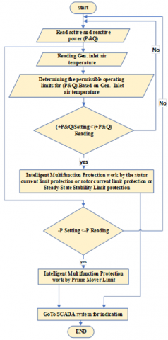
Figure 2 illustrates these operations in the form of a flowchart.
Figure 2. Flowchart for the intelligent multifunction protection system
This stage operates when the operating point (P, Q, and Temp.) goes beyond the capability curve limits of the synchronous generator.
Due to the lack of complete theoretical data for plotting the generator's capability curve, the data was taken from locally practical and factory tests of the synchronous machine (H25 type) operating in Mosul Gas Power Plant, manufactured by Hitachi, Japan. All the curve data were imported into MATLAB to generate the required dataset. This data was then fed into a Adaptive Neuro-Fuzzy Inference Systems (ANFIS) system, as input-output data set, to make the correct decision based on the values of active power, reactive power, and ambient temperature.
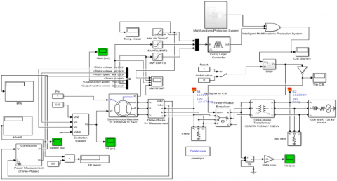
The proposed system diagram model consists of a synchronous generator with the following basic data: (32.32 MVA, 11.500 kV, power factor of 0.8, 1632 A), connected to a power transformer with a capacity of (33 MVA), and connected to an electrical grid (infinity busbar) with a voltage of 132 kV as shown in Figure 3.
Figure 3. The proposed system diagram model
Combining artificial neural network approaches with fuzzy logic, the Adaptive Neuro-Fuzzy Inference System (ANFIS) is a hybrid model that generates an intelligent system able to adapt to the environment and improve its performance depending on the input data. This system intends to use the features of fuzzy logic and neural artificial intelligence to offer answers for issues needing a great capacity to manage uncertainty and data errors [3, 35].
The use of ANFIS is advantageous due to its significant benefits, as it can adapt to changing data, since the real power, reactive power, and temperature (the inputs in the proposed intelligent phase) all vary over time. Additionally, ANFIS has the ability to handle uncertainty and ambiguity, as the working spaces for which data is entered into the intelligent phase start from (0℃) and end at (49℃), with an increase of 5 degrees for each working space. The system makes the appropriate decision when the data falls between two spaces.
It is worth noting that the generator's cooling system is an open-loop cooling system. Machine data is shown in Table 2.
Table 2. Generator parameter
|
Parameter |
Rating Value |
|
Gen rating |
(32325kVA-2P-11.5kV-50Hz-1632A-0.8PF) @15℃ Air inlet |
|
Inertia moment/(GD2) |
Aprox.800Kg.m2 |
|
Direct-axis sub-transient reactance (Xd") |
15% |
|
Direct-axis transient reactance (Xd') |
21% |
|
Direct-axis synchronous reactance (Xd) |
194% |
|
Quadrature-axis synchronous reactance (Xq) |
187% |
|
Sub-transient reactance (X2) |
15% |
|
Zero sequence reactance (Xo) |
9% |
|
Direct-axis sub-transient time constant (Td") |
0.022S |
|
Direct-axis transient time constant (Td') |
0.57S |
|
Direct-axis sub-transient time constant (Tdo") |
0.04S |
|
Direct-axis transient time constant without (Tdo') |
5.5S |
The performance and effectiveness of the proposed intelligent multifunction relay were simulated under different operating conditions for synchronous generators, including varying temperatures and loads (P, Q, and Temp.).
This data was modeled into the MATLAB Simulink program, and then fuzzy logic was employed to decide for the proposed protection, as shown in Figure 4.
Figure 4. Synchronous generator proposed module
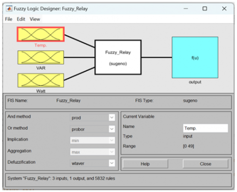
From the actual domain into the fuzzy domain, the fuzzification process is the input stage, allowing such conversion [36]. The membership function in the controller converts the input variables into linguistic variables [37]. In the present work, an Adptive neuro-fuzzy inference system (ANFIS) was used to create the FIS using an input-output data set. The resultant FIS consists of one output (trip signal) and three inputs (actual power, reactive power, and inlet air temperature), as shown in Figure 5.
Figure 5. Fuzzy logic designer block diagram
Readings of (MW, MVAR, and TEMP) were used as inputs to the FIS. These variables (inputs/outputs) are fuzzified by dividing the discourse universe into intervals for each linguistic variable. The discretization method can determine the fuzzy sets and membership functions for each variable [38]. The number of input membership functions are (18, 18, 18), training data volume is 4070 (rows)⨯4 (columns), number of epochs is 5, and the ANFIS error rate training results were equal to (0.0000001).
The performance and effectiveness of the proposed intelligent multifunction relay were simulated under different operating conditions of synchronous generators, including varying temperatures and different loads (P, Q, and Temp.).
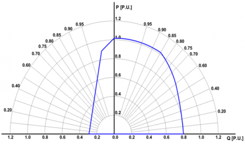
The data extracted from the local practical tests and factory test data were entered into MATLAB to generate the proposed intelligent multifunction protection limits, Figure 6 represents the limits of this data at ISO conditions, which represent synchronous machine data at 15°C, 60% humidity, and sea level at 1 bar.
Figure 6. Boundary of proposed protection at 15Cº
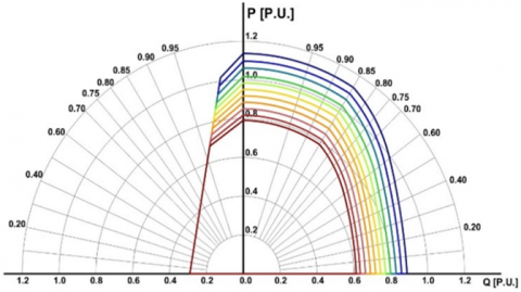
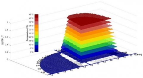
The proposed intelligent protection limits were designed to operate from a temperature of 0℃ to 49℃. Figure 7 represents eleven closed regions (Temp. 0°C, Temp. 5℃, Temp. 10°C, Temp. 15℃, Temp. 20℃, Temp. 25℃, Temp. 30℃, Temp. 35℃, Temp. 40℃, Temp. 45℃, Temp. 49℃) that represent the proposed intelligent protection limits with the inlet air temperature to the generator. The area of the curve increases as the temperature decreases and decreases as the temperature increases, starting from the largest area at 0℃ and ending with the smallest area at 49℃.
Figure 7. Boundary of proposed protection from 15℃ to 49℃
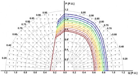
Random points were generated inside and outside the boundaries of the capability curve, representing the limits of the proposed intelligent protection stage. Each point represents the real power and reactive power coordinates, and the inlet air temperature of the generator was also included. These data (P, Q, and Air Inlet Temp.) were then processed in MATLAB Simulink and the intelligent technique (fuzzy logic) to determine whether the point lies inside or outside the proposed intelligent protection limits, as shown in Figure 8.
Figure 8. Boundary of proposed protection from 15℃ to 49℃ with Random points
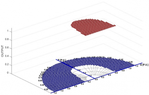
After inputting the data into the proposed protection system, it will operate as shown in Figure 9, which represents a 3D graph distinguishing between the operating region (the safe zone, shown in green for generator operation) and the shutdown region (the unsafe zone, shown in red, for generator operation) of the intelligent multifunction protection at a temperature of 49℃.
When the coordinates of the working point (P&Q) are within the limits of the power curve, the suggested intelligent protection signal is 1, which does not lead to the circuit breaker tripping. When the coordinates of the working point (P&Q) are outside the limits of the power curve, the suggested intelligent protection signal is 0, which leads to the circuit breaker tripping.
Figure 9. 3D boundary of proposed protection at 49℃
Figure 10 presents a three-dimensional representation that distinguishes all the operating regions (the safe zone for generator operation) from the tripping region (the unsafe zone for generator operation) of the proposed intelligent multifunction protection across temperatures ranging from 0°C to 49°C.
The working principle of the proposed intelligent multifunction protection in the MATLAB/Simulink program involves inputting the real power, reactive power, and temperature values into the fuzzy logic system. The program first reads the inlet air temperature to the generator to determine the proposed intelligent protection limits, then compares these limits with the actual real and reactive power generated by the synchronous generator.
If the values fall within the permissible limits, the output signal ranges from 0.1 to 1.1, depending on the operating region; if the values are outside the limits, the system generates a signal of 0 to trip the circuit breaker.
Figure 10. 3D boundary of proposed protection from 0℃ to 49℃
There are several scenarios for improving the efficiency of gas turbines, including the introduction of air-cooling systems for the intake air entering the turbine. This results in an increase in the turbine's output horsepower, thereby enhancing the capacity of the synchronous generator [39].
In this case, generators may operate beyond the limits of the capability curve, which leads to an increase in the temperature of the stator or rotor windings and may potentially cause damage. Therefore, it is essential to trip the synchronous generator when the operating point exceeds the capability curve limits based on the inlet air temperature of the generator.
The proposed intelligent multifunction protection operates in four cases.
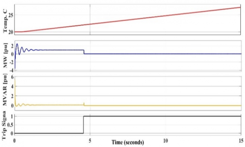
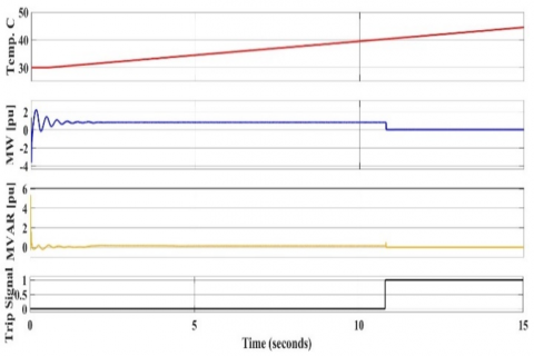
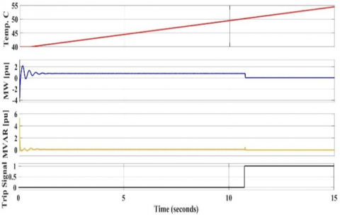
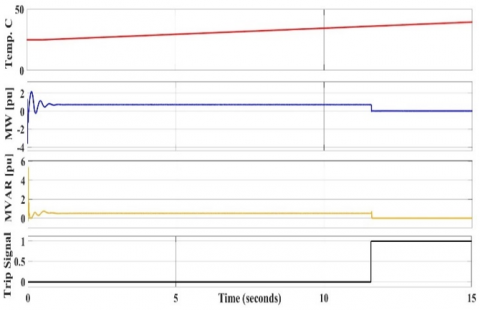
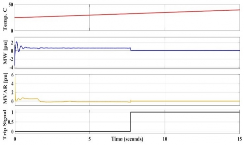
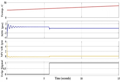
The first case is the circuit breaker tripping due to the stator current limit being exceeded in three instances, when the generator inlet air temperature was 21℃, 40℃, and 50℃, as shown in Figure 11, Figure 12 and Figure 13.
The second case is circuit breaker tripping due to the Rotor Current Limit (Field Winding Heating Limit) condition, as shown in Figure 14.
The Third case is circuit breaker tripping due to the Stability Limit (steady-state stability limit) condition as shown in Figure 15.
The fourth case is circuit breaker tripping due to the reverse power limit (prime mover limit) condition, as shown in Figure 16.
Figure 11. Trip C.B. due to stator current limit at 21.9℃
Figure 12. Trip C.B. due to stator current limit at 40.6℃
Figure 13. Trip C.B. due to stator current limit at 50.3℃
Figure 14. Trip C.B. due to rotor current limit at 30.6℃
Figure 15. Trip C.B. due to steady-state stability limit at 20.5℃
Figure 16. Trip C.B. due to prime mover limit at 22.5℃
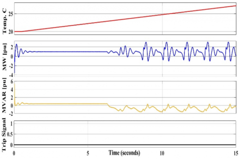
Figure 17. Loss of synchronism
Considered a fundamental operational condition directly influencing the performance and stability of a synchronous generator is the decrease of excitation current in that generator. The magnetic field weakens when the excitation current falls below the necessary level, so lowering the generated voltage and raising the reactive power consumed from the grid. As so, the magnetic field becomes inadequate to preserve synchronism between the rotor and the rotating magnetic field generated by the stator currents. At this point the generator loses synchronism with the electrical grid and starts running as a induction generator, where rather than from self-excitation the magnetic field is induced by currents resulting from the magnetic flux of the grid. Though technically feasible, this running mode is usually unstable and depends totally on the grid to provide the required excitation. A synchronous generator switching to induction generator mode can cause major stability problems and perhaps cause generator damage; this is the fifth case as shown in Figure 17.
Table 3. The operating and tripping values of the proposed protection
|
Case Name |
Operation Condition |
Trip Signal Condition |
||||
|
Temp. |
Q(pu) |
P(pu) |
Temp. |
Q(pu) |
P(pu) |
|
|
Case1 |
Up to 21℃ |
0.105 |
0.976 |
21.9℃ |
0.127 |
0.970 |
|
Up to 40℃ |
0.132 |
0.839 |
40.6℃ |
0.133 |
0.840 |
|
|
Up to 50℃ |
0.11 |
0.787 |
50.3℃ |
0.116 |
0.79 |
|
|
Case2 |
Up to 30℃ |
0.63 |
0.51 |
30.6℃ |
0.63 |
0.515 |
|
Case3 |
Up to 49℃ |
-0.2 |
-0.17 |
20.5℃ |
-0.2 |
-0.17 |
|
Case4 |
Up to 49℃ |
-0.4 |
0.7 |
22.5℃ |
-0.8 |
0.7 |
Table 4. Types of faults and its protections
|
Protection Name |
Fault Name |
|
Over current |
LG fault, LL fault, LLL fault |
|
Over excitation |
AVR control fault |
|
Loss of excitation |
Excitation C.B fault, rotor winding, short or open circuit, AVR control fault |
|
Reverse power |
Prime mover fault |
|
Proposed protection |
LG fault, LL fault, LLL fault, AVR control fault, Excitation C.B fault, rotor winding short or open circuit, AVR control fault |
Table 3 shows the proposed intelligent phase's operating and tripping values for the four cases explained above.
The conventional system includes separate protection schemes for each type of fault, whereas the proposed system is capable of handling multiple types of faults using a unified protection scheme, as shown in Table 4.
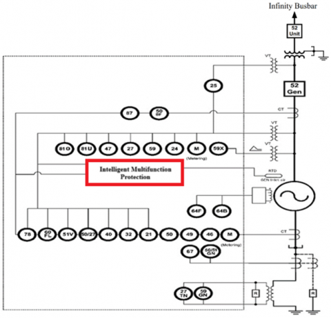
For each protection function of the synchronous generator, a unique function number is assigned in accordance with the IEEE C37 standard. The following Table 5 lists the function numbers defined by the IEEE C37.2 standard.
Table 5. Generator protection elements
|
Device |
Description |
ANSI |
|
Current element |
Differential protection |
87G |
|
Over current |
51V |
|
|
Negative phase sequence |
46NPS |
|
|
Voltage element |
Over voltage |
59OV |
|
Under voltage |
27UV |
|
|
Volt / Hz |
24 |
|
|
Over frequency |
81O |
|
|
Under frequency |
81U |
|
|
VT – fuse failure |
60 |
|
|
Power element |
Reverse power |
32R |
|
Low forward power |
32L |
|
|
Neutral side protection |
Stator earth fault |
51N |
|
Neutral displacement |
59N |
|
|
Excitation protection |
Field failure |
40FF |
|
Rotor protection |
Rotor earth failure |
64F |
|
DC overcurrent |
76 |
While each standard protection function for a synchronous generator typically addresses a specific protection aspect, the proposed protection scheme integrates multiple protection functions into a single system. These include: overcurrent (51V), reverse power (32R), DC rotor overcurrent (76), loss of excitation (40FF).
In this research, based on the generator inlet air temperature, a model for an intelligent multifunction protection system was designed to protect synchronous generators from operating beyond the permissible limits of real and reactive power. These limits include the rotor current limit, stator current limit, steady-state stability limit, and prime mover limit.
The proposed model was implemented using MATLAB/Simulink software, incorporating fuzzy logic. The design is characterized by fast performance, as the generator inlet air temperature plays an important role in the system's operation.
The results showed a good response from the proposed protection system with an increase the generator inlet air temperature, which significantly affects the decision-making of the proposed stage. Overcurrent protection or overexcitation protection may be not exceed the protection setting values, but there is a risk to the generator due to the operating point exceeding the generator’s capability curve characteristics caused by the rise in the generator inlet air temperature. It is very important to apply this model in generator units that use turbine engine efficiency improvement systems or use cylinder engines, as they are more efficient than turbine engines, where the generator cooling is done by an open-loop system.
This protection covers various types of protection, including overcurrent protection, overexcitation protection, reverse power protection, failure of excitation protection, and out-of-synchronization protection. However, the proposed protection does not cover all types of generator protection, such as instantaneous overcurrent protection and differential protection.
It is essential to activate overvoltage and undervoltage protection because the proposed protection works based on the real and reactive power coordinates, The operating point may lie within the generator’s capability curve but at low or high voltage, which could result in the protection not being activated.
This protection can be used as primary protection for stator current and rotor current limits because the standard values for these protections vary with the generator inlet air temperature. The protection setting value decreases as the generator inlet air temperature rises, and vice versa. It serves as backup protection for stability limits in steady-state operation and the prime mover limit, as the protection setting values for these protections remain fixed and are unaffected by changes in the generator inlet air temperature.
Many future technical works can be studied, analyzed, and implemented to enhance the protection of synchronous generators in the electrical power system. These include: differential protection, as the proposed protection is not effective against faults within the generator windings; overvoltage and undervoltage protection; overfrequency and underfrequency protection; negative sequence current protection; and restricted earth fault protection. The aim is to integrate these protections with the proposed scheme to develop a comprehensive intelligent multifunctional protection device.
The authors would like to sincerely thank the University of Mosul, College of Engineering, Electrical Engineering Department, for the support of this work.
[1] Javaid, S., Kaneko, M., Tan, Y. (2021). Safe operation conditions of electrical power system considering power balanceability among power generators, loads, and storage devices. Energies, 14(15): 4460. https://doi.org/10.3390/en14154460
[2] Qasim, A.Y., Tahir, F.R., Alsammak, A.N.B. (2024). Improving power quality in distribution systems using UPQC: An overview. Journal Européen des Systèmes Automatisés, 57(2): 311-322. https://doi.org/10.18280/jesa.570201
[3] Alsammak, A.N.B., Al-Kaoaz, H.N.A. (2023). Design of a fuzzy distance relay taking into consideration the impact of using a unified power flow controller. Eastern-European Journal of Enterprise Technologies, 122(5): 6. https://doi.org/10.15587/1729-4061.2023.277343
[4] Alnaib, I.I., Alsammak, A.N.B., Sabry, S. (2022). Protection relay performance comparison for faults detection and classification based on ANN and ANFIS. In Control, Instrumentation and Mechatronics: Theory and Practice, pp. 545-555. https://doi.org/10.1007/978-981-19-3923-5_47
[5] Andrade, I., Pena, R., Blasco-Gimenez, R., Riedemann, J., Jara, W., Pesce, C. (2021). An active/reactive power control strategy for renewable generation systems. Electronics, 10(9): 1061. https://doi.org/10.3390/electronics10091061
[6] Brodzicki, M., Klucznik, J., Czapp, S. (2023). Evaluation of VSC impact on power system using adequate PQ capability curve. Electronics, 12(11): 2462. https://doi.org/10.3390/electronics12112462
[7] Xu, B., Ao, F., Yan, Y., Fan, O., Li, H. (2024). Research on the impact of large-scale renewable energy power generation on relay protection. Eighth International Conference on Energy System, Electricity, and Power (ESEP 2023), 13159: 132-137. https://doi.org/10.1117/12.3024651
[8] Smil V. (2007). The two prime movers of globalization: History and impact of diesel engines and gas turbines. Journal of Global History, 2(3): 373-394. https://doi.org/10.1017/S1740022807002331
[9] Lee, C.Y., Tuegeh, M. (2021). Virtual visualization of generator operation condition through generator capability curve. Energies, 14(1): 185. https://doi.org/10.3390/EN14010185
[10] Sizykh, V., Vostrikov, M., Daneev, A., Menaker, K. (2022). Automation of the process of measurement of electrical parameters in microprocessor devices of relay protection. Transportation Research Procedia, 61: 467-474. https://doi.org/10.1016/j.trpro.2022.01.076
[11] Yerbolkyzy, G., Tatkeyeva, G., Uakhitova, A. (2025). Operation analysis of fuzzy logic-based relay protection devices. Electric Power Systems Research, 241: 111390. https://doi.org/10.1016/j.epsr.2024.111390
[12] Ruan, L., Tac, Q., Cui, Y., Pang, S., Yin, X., Xu, B. (2019). A novel inverse time protection scheme of large generator based on polynomial optimal fitting. In 2019 IEEE Asia Power and Energy Engineering Conference (APEEC), Chengdu, China, pp. 206-211. https://doi.org/10.1109/APEEC.2019.8720723
[13] Rathogwa, K.L., Krishnamurthy, S. (2024). Hardware-in-the-loop simulation and testing of volts per hertz protection scheme for a generator over-excitation system. International Journal of Power and Energy Conversion, 15(2): 147-165. https://doi.org/10.1504/IJPEC.2024.138008
[14] Majeed, A.A., Altaie, A.S., Abderrahim, M., Alkhazraji, A. (2023). A review of protection schemes for electrical distribution networks with green distributed generation. Energies, 16(22): 7587. https://doi.org/10.3390/en16227587
[15] Rezaei, N. (2023). Emerging technologies in design and testing of protection relays for transmission system connected to inverter based resources. In 22nd Wind and Solar Integration Workshop (WIW 2023), Copenhagen, Denmark, pp. 712-719. https://doi.org/10.1049/icp.2023.2807
[16] Alahmed, S.H.A., Alsammak, A.N.B., Mohammed, H.A. (2025). A review of the conventional and intelligent multifunctions electrical generator protection system, challenges and opportunities. Journal Européen des Systèmes Automatisés, 58(3): 523-536. https://doi.org/10.18280/jesa.580310
[17] Singh, M. (2024). A guide to protection schemes of synchronous generator-based electric grids. e-Prime-Advances in Electrical Engineering, Electronics and Energy, 10: 100769. https://doi.org/10.1016/j.prime.2024.100769
[18] Sekhane, H., Labed, D., Labed, M.A. (2022). Modelling and performance testing of a digital over-current relay enhanced designed model. Electrical Engineering & Electromechanics, 3: 71-78. https://doi.org/10.20998/2074-272X.2022.3.10
[19] Zhao, X., Zhang, H., Zhu, H., Hu, Q., Zhang, L. (2024). An emergency control considering current limitation and transient stability of virtual synchronous generator. IET Generation, Transmission & Distribution, 18(8): 1641-1652. https://doi.org/10.1049/gtd2.13148
[20] Baracho, F.R., Coelho, A.L., Damião, L.J., Zvietcovich, W.G. (2022). Real-time digital simulation for coordination analysis of V/Hz AVR limiter with overexcitation, overvoltage, and underfrequency protections of synchronous generators. IEEE Transactions on Industry Applications, 58(3): 3361-3369. https://doi.org/10.1109/TIA.2022.3160681
[21] Reinap, A., Estenlund, S., Högmark, C. (2025). Hollow direct air-cooled rotor windings: Conjugate heat transfer analysis. Machines, 13(2): 89. https://doi.org/10.3390/MACHINES13020089
[22] Xu, M.X., He, Y.L., Zhang, W., Dai, D.R., Chen, S.C., Zhou, H. (2025). Impact of RISC positions on stator winding insulation in synchronous generators. Electrical Engineering, 107: 10227–10240. https://doi.org/10.1007/s00202-025-03024-8
[23] Noroozi, N., Alinejad-Beromi, Y., Yaghobi, H. (2019). Fast approach to detect generator loss of excitation based on reactive power variation. IET Generation, Transmission & Distribution, 13(4): 453-460. https://doi.org/10.1049/iet-gtd.2018.5049
[24] Qian, Z. (2020). Analysis and preventive measures of excitation system failure leading to two downtime accidents. IOP Conference Series: Earth and Environmental Science, 512(1): 012171. https://doi.org/10.1088/1755-1315/512/1/012171
[25] Noroozi, N., Yaghobi, H., Alinejad-Beromi, Y. (2017). Analytical technique for synchronous generator loss-of-excitation protection. IET Generation, Transmission & Distribution, 11(9): 2222-2231. https://doi.org/10.1049/iet-gtd.2016.1494
[26] Choi, S.S., Jia, X.M. (2002). Under excitation limiter and its role in preventing excessive synchronous generator stator end-core heating. IEEE Transactions on Power Systems, 15(1): 95-101. https://doi.org/10.1109/59.852106
[27] Ygzaw, A., Banteyirga, B., Darsema, M. (2019). Generator excitation loss detection on various excitation systems and excitation system failures. In International Conference on Advances of Science and Technology, pp. 382-394. https://doi.org/10.1007/978-3-030-43690-2_26
[28] Flores, A., Zárate-Miñano, R., Carrión, M. (2023). Capability curve modeling for hydro-power generators in optimal power flow problems. Sustainability, 15(24): 16654. https://doi.org/10.3390/su152416654
[29] Joksimović, D., Stojić, D., Veinović, S., Marčetić, D. (2025). Reactive power controller for under-excitation limiter with regard to electromechanical oscillations. IEEE Access, 13: 59339-59365. https://doi.org/10.1109/ACCESS.2025.3555960
[30] Barabanov, N., Schiffer, J., Ortega, R., Efimov, D. (2017). Conditions for almost global attractivity of a synchronous generator connected to an infinite bus. IEEE Transactions on Automatic Control, 62(10): 4905-4916. https://doi.org/10.1109/TAC.2017.2671026
[31] Messerle, H.K., Bruck, R.W. (1956). Steady-state stability of synchronous generators as affected by regulators and governors. Proceedings of the IEE-Part C: Monographs, 103(3): 24-34. https://doi.org/10.1049/pi-c.1956.000
[32] Yaghobi, H. (2018). Fast predictive technique for reverse power detection in synchronous generator. IET Electric Power Applications, 12(4): 508-517. https://doi.org/10.1049/iet-epa.2017.0491
[33] Mishra, D.P., Senapati, R., Patra, S., Mishra, B., Aprameya, A. (2021). Enhancing the performance of reverse power relay for generator protection. WSEAS Transactions on Power Systems, 16: 336-343. https://doi.10.37394/232016.2021.16.33
[34] Samami, M., Azari, M.N. (2019). Novel fast and secure approach for reverse power protection in synchronous generators. IET Electric Power Applications, 13(12): 2128-2138. https://doi.org/10.1049/iet-epa.2018.5961
[35] Mohammed, H.A., Alsammak, A.N.B. (2023). An intelligent hybrid control system using ANFIS-optimization for scalar control of an induction motor. Journal Européen des Systèmes Automatisés, 56(5): 857-862. https://doi.org/10.18280/jesa.560516
[36] Rezaie, H., Kazemi-Rahbar, M.H. (2019). Enhancing voltage stability and LVRT capability of a wind-integrated power system using a fuzzy-based SVC. Engineering Science and Technology, an International Journal, 22(3): 827-839. https://doi.org/10.1016/J.JESTCH.2018.12.018
[37] Zand, B., Ghaderi, P., Amini, F. (2023). Structural system identification via synchronization technique and fuzzy logic. Mathematics and Computers in Simulation, 203: 174-188. https://doi.org/10.1016/j.matcom.2022.06.009
[38] Saleem, B., Badar, R., Judge, M.A., Manzoor, A., ul Islam, S., Rodrigues, J.J. (2021). Adaptive recurrent NeuroFuzzy control for power system stability in smart cities. Sustainable Energy Technologies and Assessments, 45: 101089. https://doi.org/10.1016/J.SETA.2021.101089
[39] Sánchez Cabarcas, M.E., Bedoya Villegas, J.A., Sierra Aragón, Á.D., Rodríguez Roldán, I., et al. (2024). Enhancing gas turbine power plant performance in tropical climates by using inlet air cooling with desiccant dehumidification and evaporative cooling. Journal of Thermal Science and Engineering Applications, 16(1): 011006. https://doi.org/10.1115/1.4063679