Abdelkrim Rechach* | Sihem Ghoudelbourk | Zoubir Aoulmi | Dib Djalel
© 2021 IIETA. This article is published by IIETA and is licensed under the CC BY 4.0 license (http://creativecommons.org/licenses/by/4.0/).
OPEN ACCESS
Switched reluctance motors (SRM) are a type of electromagnetic machine that has piqued the interest of manufacturers, as opposed to induction, brushless, or permanent magnet machines. This is because the rotor is simple, robust, and lacks coils, windings, and permanent magnets. It can also operate in a wide range of power in the electric vehicle's drive, even in extreme conditions such as underground mines, ensuring a longer life of service. However, due to the toothed shape of the rotor, the SRM is characterized by vibration and acoustic noise. To solve this problem to better adapt the SRM to the electric vehicle, we propose to use intelligent techniques such as the controller (ANN) and the fractional order controller (PIα). This article compares two intelligent speed controllers that use direct torque control (DTC) to reduce torque ripples. As a result, when associated with direct torque control, the Fractional Order Controller (PIα) outperforms the Artificial Neural Network (ANN).
direct torque control, artificial neural network controller, fractional order controller, switched reluctance motor, electrical vehicle, underground mines security
The mining industry is moving toward lowering its environmental impact, and major players are working to eliminate diesel vehicles that generate significant greenhouse gas emissions and incur high operating costs. There are currently no electric vehicles on the market that meet stringent operational and climate requirements for underground and open pit mines. Given the new demands of the mining industry, the development of electric mining vehicles has become a necessity.
The new directions focus on the development of a new electric propulsion system with a rapid charging infrastructure suitable for light and heavy vehicles in the open pit and underground mining industry. It is interesting that the very innovative aspects of the chosen technology solution are designed to be applicable to different types of mining vehicles.
The main purpose of this article is to promote the proper use of the remote-controlled electric vehicle entrained by an SRM in underground mines. The choice of this latter depends on the reliability and ability to work in extreme conditions with humidity, heat, dusty dust and harmful atmospheres. Equipped with sensors and suitable cameras, this vehicle is recommended for safe mining. It is very useful for detecting explosive fires, mountain peak observations, landslide detection, and highly toxic flue gases from landslides and groundwater intrusion to avoid flood hazards and to visualize potential fires that could occur hundreds of meters underground. Due to its purity, these SRM-powered vehicles do not pollute the atmosphere unlike fossil fuel vehicles.
Our choice focused on the use of the SRM for its many advantages, namely: simple structure of the rotor, robustness, without coils, windings, permanent magnets, brushes, or sparks under the brushes (which will exclude the risk of cause fires or explosions due to the existence of flammable atmospheres in mines such as firedamp), excellent performance in extreme environments, high overload capacity, low manufacturing and maintenance costs, and operation in a wide power range.
However, research is hampered by strong vibrations due to peripheral discontinuities of its rotor which are prohibitive to make it the motor of the first choice. SRMs have certain disadvantages which are: torque ripples, vibrations, and acoustic noises. To better use the SRM as a drive for this electric mining safety vehicle, we suggest employing intelligent techniques such as the ANN controller and the fractional order controller PIα to optimize the effect of torque ripples. Both techniques are associated with DTC, which seems very well suited for SRM applications due to the advantage of not having speed and position sensors and only using voltage and current to evaluate and compare magnetic flux, torque and speed.
After simulation in the Matlab/Simulink environment, and after comparing the use of two smart controllers, we concluded that the response seems even more improved if we associate the DTC with a fractional order controller, which offers better stability, a speed without overshoot, and better behavior to load disturbances, which increases the machine longevity and robustness compared to those obtained with ANN controller.
Different techniques have been proposed in the past to minimize torque ripples. Warpatkar and Dalvi [1] presented a new approach for minimizing torque ripple in an SRM 8/6 poles using computational methods for the design calculation. According to this, the combination of calculations including mechanical, electromagnetic, and electrical design as well as laboratory tests and appropriate investments play an essential role in the development of a successful SRM design. Nagesh et al. [2] modeled and analyzed the SRM 8/6 with a simple PI controller and showed after simulation that torque ripples were reduced for different load values.
Pratapgiri and Narsimha [3] have put in evidence that theDTC technique can minimize torque ripple by regulating torque with a specified hysteresis band. A four-phase non-symmetrical converter has a total of 81 space voltage vectors while only 8 space voltage vectors are sufficient to apply the DTC technique to the SRM.
Ghani et al. [4] asserted based on the simulation results that the fuzzy logic controller produces better results. When compared to the results obtained by the ANN controller, the torque ripple has become weaker and the current waveform has become smoother.
In 2015, Shrivastava [5] used the fuzzy logic controller of the SRM 8/6 in combination with the DTC. This proposed technique reduced torque ripples and current distortion, produced a very fast torque response and good control precision.
This article compares the use of two intelligent speed controls associated with direct torque control (DTC) to minimize torque ripples caused by peripheral discontinuities imposed by the shape of the SRM rotor. The DTC associated with the fractional order controller (PIα) is better than that associated with the controller of the artificial neural network (ANN).
In underground mines, there are extreme conditions such as moisture, heat, dust, voltage, lack of oxygen, harmful atmosphere, highly toxic flue gases after explosion works, landslides, rockfall, groundwater and flood, and fire. The danger and darkness are often reinforced by the dark walls. This requires a highly developed security system, and to facilitate this, a remote controlled electric vehicle with sensors, gas sampling strips and cameras that can measure atmospheric and gas parameters and record the safe state of the mine to avoid danger, like injuries to medical personnel during critical times, especially after an explosive fire and in the event of an accident.
The remote control electric car is the right choice for purity, safety and speed. However, it is often driven by an induction motor that cannot withstand the extreme mining conditions mentioned above. When comparing IM induction motors, permanent magnet synchronous motors and SRMs with the same characteristics (torque, speed) [6], we note the following in Table 1.
Table 1. Comparisons between IM, synchronous motors and SRMs
|
Electric motor |
Advantages |
Disadvantages |
|
Synchronous motors |
|
|
|
Induction motors |
|
|
|
SRM |
|
|
Table 2. Comparisons between four types of electric motor drives
|
Index |
DC motor |
IM drives |
PM BLDC |
SRM |
|
Efficiency |
2 |
4 |
5 |
4.5 |
|
Weight |
2 |
4 |
4.5 |
5 |
|
Cost |
5 |
4 |
3 |
4 |
|
Total |
9 |
12 |
12.5 |
13.5 |
The advantages and disadvantages of the four solutions for electrical wiring are summarized in Table 2 [7]. Each motor is rated from 0 to 5 and the best solution is 5 criterions. As you can see, SRM is a competitive electric traction solution with light weight, very high efficiency and low production cost.
The use of conventional controllers, such as the PI regulator, does not produce good results, and despite improvements, vibrations are still unacceptable, particularly with the use of sensors and cameras mounted on the electric mine safety vehicle, which require better stability, or a significant reduction in torque ripples.
Torque ripples can be minimized by using the (DTC) technique. Furthermore, the absence of position sensors relieves the stator of clutter, and the motor benefits from improved air circulation between the polar windings which significantly promotes cooling and increases its efficiency. Note that the DTC technique estimates speed and torque by simply measuring the supply voltage and current and does not use speed sensors and observers.
However, in order to achieve better results with fewer vibrations, we chose the best in intelligent control: Control by ANN and the fractional-order controller PIα both associated with the DTC.
After simulation at a Matlab/Simulink environment, we validated the results by comparison with recent related work, which demonstrated the superiority and efficiency of the PIα fractional order controller in association with the DTC.
4.1 Switched reluctance motor model
SRMs are similar in their mode of operation, but for reasons of simplification, the characteristics mentioned below in Table 3 of the SRM taken as the object of our study, are identical to those appearing in Ref. [8].
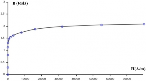
The selection of ferromagnetic material characterizes the magnetic properties capable of significantly increasing the motor's efficiency. Because the surface of the latter determines the magnetic losses, ferromagnetic materials for SRMs are chosen using the criterion of the narrowest hysteresis cycle possible. Figure 1 shows the first magnetization curve B=f(H) of the ferromagnetic material used here (Steel M19). It is important to specify that the simulation will be made for the magnetic unsaturation zone.
Table 3. The main characteristics of the SRM chosen
|
Designation |
Notation |
Dimension |
|
Outside stator radius |
Rs |
143 mm |
|
Rotor radius |
Rr |
69 mm |
|
Air Gap |
E |
0.40 mm |
|
Polar arc of the stator |
Вs |
0.416 rd |
|
Polar arc of the rotor |
Br |
0.492 rd |
|
Stator tooth height |
hs |
24,50 mm |
|
Rotor tooth height |
hr |
12,50 mm |
|
Stator pole width |
Bs |
30 mm |
|
Rotor pole width |
Br |
30 mm |
|
Stator yoke thickness |
Ys |
12,10 mm |
|
Rotor yoke thickness |
Yr |
9,00 mm |
|
Stack length |
SL |
143 mm |
|
Shaft Radius |
Ra |
13 mm |
|
Number of coil turns |
Ns |
180 |
|
Ferromagnetic material |
M19 |
M19 |
|
Maximum Current |
I |
30 A |
|
Maximum Flux |
ɸmax |
0,30 Wb |
|
Stator poles |
NPs |
8 |
|
Rotor poles |
NPr |
6 |
The basic practical design of SRM was developed with higher efficiency than induction motors of the same size thanks to the work of Lawrenson et al. [9], among other things; he established the design rules for the polar arcs of the stator and the rotor, as well as the flux waveforms in the different positions of the rotor.
Figure 1. Magnetization curve of M19 steel, B=F (H)
After the interest and acceptance of SRM technology has grown huge. Miller [10] presented the first book dealing only with SRM technology which allowed manufacturers to develop series of SRM products, with half the volume of conventional DC and AC motors.
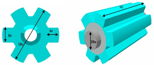
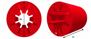
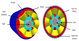
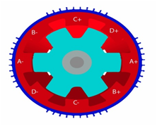
The main idea of the operation of the SRM is that windings housed in the stator teeth are energized alternately, while the rotor teeth, without windings or magnets, are attracted adequately to the stator windings [7]. The figures below depict the design topology of the prototype of the rotor and stator object of our simulation with a four-phase power supply of the SRM 8/6. Figure 2 depicts the rotor structure with SRM 8/6 poles. Figure 3 is a clear picture of the poles lamination of the stator without winding and the different parts of the previous figures have been assembled in Figure 4 which shows the whole machine with its different parts.
Figure 2. Structure showing the rotor of the SRM and its poles
Figure 3. The stator lamination of the SRM 8/6poles without winding
Figure 4. The entire structure of SRM 8/6poles with its different parts
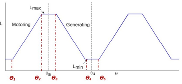
The principle of operation of an SRM is essentially based on the position of the rotor tooth with the stator tooth. Figure 5 shows schematically how the 4 phases are connected around the stator poles. When a phase is supplied, the rotor turns to the position where the flux created by the stator is maximal [11]. This case is called the conjunction position. The opposition position is the opposite position with the least amount of flux. The torque is created by magnetic variation between the stator pole and the rotor pole, hence its name “Switched reluctance motor” [12, 13]. During a cycle of variation of the magnetic permeability four periods are observed [14]:
$\begin{array}{ll}L_{\min } & 0 \leq \theta<\theta_{1} \\ L_{\min }+p \theta & \theta_{1} \leq \theta<\theta_{2} \\ L(\theta)=L_{\max } & \theta_{2} \leq \theta<\theta_{3} \\ L_{\max }-p\left(\theta-\beta_{r}\right) & \theta_{3} \leq \theta<\theta_{4} \\ L_{\min } & \theta_{4} \leq \theta<\theta_{5}\end{array}$ (1)
L(θ): Inductance variation over one rotor pole pitch,
Lmin: Unaligned inductance (H),
Lmax: Aligned inductance (H),
βs: Stator pole arc(rad),
βr:Rotor pole arc(rad) βr>βs.
Figure 5. Connection of the 4 phases of the stator for SRM 8/6
$p=\frac{L_{\max }-L_{\min }}{\beta_{s}}$ (2)
The idealized form of the inductance of a phase as a function of the rotor position is shown in Figure 6.
Figure 6. Inductance profile for switched reluctance motor
The electric supply voltage of the stator winding of the motor is given by:
$v=R i+\frac{d \psi(\theta, i)}{d t}$ (3)
dψ(Ɵ,i) is the phase flux linkage as a function of rotor position θ and stator current I. We deduce:
$v=R i+\frac{d \psi(\theta, i)}{d i} \frac{d i}{d t}+\frac{d \psi(\theta, i)}{d \theta} \frac{d \theta}{d t}$ (4)
The mechanical energy [8] is shown as:
$d W_{m}=i \frac{d \psi(\theta, i)}{d \theta} d \theta-\frac{d W_{f}}{d \theta} \frac{d \theta}{d t}$ (5)
The torque equation is defined as:
$T \approx i \frac{d \psi(\theta, i)}{d \theta}$ (6)
4.2 DTC for SRM 8/6 poles used for electric vehicle
The technique known as direct torque control is a protocol to reduce vibrations and acoustic noise due to torque ripples caused by the rotor shape of the SRM. The performance of the DTC control of the SRM 8/6 and its impact on the torque ripple in the steady and the transient state, are used in this article in conjunction with, on the one hand, control by Artificial Neural Network and on the other with fractional-order control. A comparison between the two controls is made under the Matlab/Simulink environment.
Direct Torque Control, does not require speed or position sensors and uses only voltage and current measurements. Magnetic flux and torque are estimated and maintained when selecting the corresponding voltage vector. This makes the DTC very suitable for electric vehicles.
According to Eq. (6), the phase flux depends on the position of the rotor (θ) and the stator current (i). The DTC technique for SRM can be explained as follows [15, 16]: The unbalanced converter is often used for SRM drives (As shown in Figure 7). Each power phase has three possible voltage states.
When both switches are turned ON, current flows through two switches and a coil to apply a positive voltage to the motor phase (as shown in Figure 8a).; "Magnetizing state".
Figure 7. Asymmetric converter
Figure 8. SRM voltage states: a- State (1); b- State (0); c- State (-1)
Figure 8.b depicts what happens when the switch is turned OFF, current flows through the diode and coil, and a zero voltage loop occurs "freewheel state 0 ". In Figure 8.c, the two switches are deactivated, the current flows through the diodes and the phase winding, however, a negative voltage is applied "it is the state (-1) said demagnetizing". The unbalanced 4-phase converter (Figure 7) can have up to 81 different Space Voltage Vectors, but for the DTC applied to the SRM, only eight spatial voltage vectors are sufficient as shown clearly in Figure 9.
The proposed technique is a 4-phases spatial vector modulation (SVM) based DTC for SRM 8/6 by choosing an appropriate set of 8 spatial voltage vectors. Pulse Width Modulation (PWM) is not used. The inverter receives the commands directly and successively (see Figure 9). If the kth sector is considered for the stator flux link vectors, the spatial voltage vectors Vk+1 and Vk+2 are selected for a required increase in torque and if a decrease in torque is requested, the voltage vectors which decelerate the vector of flux Vk-1 and VK-2 are applied.
Based on the output of the hysteresis blocks where torque and flux are estimated, the appropriate spatial voltage vectors are shown in the following Table 4.
Figure 9. Space voltage vectors and 8 sectors
Table 4. DTC switching table for SVM
|
N |
ΨQ=1 |
ΨQ = 0 |
||
|
|
TQ=1 |
TQ=0 |
TQ=1 |
TQ=0 |
|
1 |
V2 |
V7 |
V3 |
V6 |
|
2 |
V3 |
V8 |
V4 |
V7 |
|
3 |
V4 |
V1 |
V5 |
V8 |
|
4 |
V5 |
V2 |
V6 |
V1 |
|
5 |
V6 |
V3 |
V7 |
V2 |
|
6 |
V7 |
V4 |
V8 |
V3 |
|
7 |
V8 |
V5 |
V1 |
V4 |
|
8 |
V1 |
V6 |
V2 |
V5 |
|
1 |
V2 |
V7 |
V3 |
V6 |
|
2 |
V3 |
V8 |
V4 |
V7 |
|
3 |
V4 |
V1 |
V5 |
V8 |
|
4 |
V5 |
V2 |
V6 |
V1 |
|
5 |
V6 |
V3 |
V7 |
V2 |
|
6 |
V7 |
V4 |
V8 |
V3 |
|
7 |
V8 |
V5 |
V1 |
V4 |
|
8 |
V1 |
V6 |
V2 |
V5 |
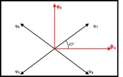
The vectors of the fluxes of the four phases are solved in the α-β axes [17, 18] using the transformation shown in Figure 10. The equation of magnetic fluxes in the α-β axes is obtained as:
$\psi_{\alpha}=\psi_{1} \cos 45^{\circ}-\psi_{2} \cos 45^{\circ}-\psi_{3} \cos 45^{\circ}+\psi_{4} \cos 45^{\circ}$ (7)
$\psi_{\beta}=\psi_{1} \sin 45^{\circ}+\psi_{2} \sin 45^{\circ}-\psi_{3} \sin 45^{\circ}+\psi_{4} \sin 45^{\circ}$ (8)
$\psi_{s}=\sqrt{\left(\psi_{\alpha}^{2}+\psi_{\alpha}^{2}\right)}$ (9)
$\delta=\arctan \left[\frac{\psi_{\alpha}}{\psi_{\beta}}\right]$ (10)
ψ1, ψ2, ψ3and ψ4: Are flux phases
ψα, ψβ: Respectively the fluxes in α and β axes
$\delta$: Angle of flux vector
Figure 10. Vectors of fluxes of 4 phases in the α, β axes
Figure 11 shows the diagram of DTC for SRM 8/6 poles. The measured values are the voltages and currents of each of the four phases at the output of the inverter which supplies the SRM. The magnetic flux of each phase is calculated and then transformed according to the α-β axes where the flux in four phases is converted into two phases. The amplitude Ψs and the angle δ of the flux vector are automatically recognized. The amplitude of the flux vector Ψs, and the calculated motor torque T, are then introduced into the flux and torque hysteresis blocks. The reference flux is compared to the real flux as well as the reference torque and the real torque which leads to an increase or decrease in flux Ψ and torque T.
The switching tables and the asymmetric converter apply the voltage vectors suitable for the four-phase windings of the SRM.
The actual speed and the reference speed are compared and the error is transmitted to the PI controller.
4.3 The PI-ANN controller for the SMR8/6
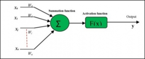
Artificial neural networks are structures built around a collection of cells (neurons) that are linked together using weighted and modifiable links during a process known as learning [19, 20]. The formal neuron (see Figure 12) consists of three basic elements:
- A set of links, each characterized by a weight wj (or synaptic coefficient), corresponding to the efficiency of the connection and a particular input x0 always equal to 1, which makes it possible to add flexibility to the network by varying the threshold of triggering of the neuron by the adjustment of its weight, commonly called bias and noted b, when learning w0 = b.
- An adder or summing unit for summing the weighted signals.
- A threshold activation function to limit the amplitude of the output value.
The objective of a learning algorithm in the ANN is to adapt the weights of the network iteratively until the error between the reference input and that measured or estimated is less than the target value.
Figure 11. Diagram of DTC for SRM 8/6 poles
Figure 12. Model of the formal neuron
Figure 13. Sensorless block diagram for SRM 8/6 using Artificial Neural Network with DTC
The DTC control strategy has been implemented. As shown in Figure 13, ANN was designed with the error between the reference speed and the estimated speed as input values.
The behavior of an existing conventional controller (PI, PID) can be reproduced by a neural network thanks to its learning and approximation capacity. The proposed model makes it possible to calculate the reference torque (Tref) from the error (e) and its derivative (Δe) by following the following steps [21, 22]:
- Set the number of hidden layers: apart from the input and output layers. The analyst must decide on the number of intermediate layers,
- Determine the number of neurons in the hidden layers: with each addition of a neuron, specific profiles of the specific input neurons must be taken into account,
- Determine the activation function.
4.4 The PI fractional controller of the SMR8/6
The applications of fractional calculus are very modern because we have been able to update a process whose study of their models corresponds to the fractional-order derivative and is expressed with the fractional power pole equation (PPE):
$G(s)=\frac{1}{{{s}^{\alpha }}}=\frac{K}{{{(1+\frac{s}{{{W}_{f}}})}^{\alpha }}}$ (11)
Here α is a non-integer real number or even a complex number; S is the Laplace transform of differentiation and Wf is the fractional pole (cutoff frequency). The use of this system in the SRM control was motivated by the superior performance of fractional order systems when compared to PI integer order. PIα Dβ is the form of the fractional regulator and it is an extension of the PID regulator which has the transfer function [23, 24]:
$H(S)={{K}_{p}}+{{K}_{i}}.{{S}^{-\alpha }}+{{K}_{d}}.{{S}^{+\beta }}$ (12)
α and β are both positive real numbers; Kp, Ki and Kd are respectively the proportional, integral, and derivative gain. If α = 1 and β= 1 we obtain the classic PID regulator.
In the numerical implementation of a Fractional Order Control, the most important step is the numerical evaluation of the discretization of the fractional-order derivations Sα. The fractional-order ordering system is characterized by the following transfer function [25, 26]:
$G(S)=\frac{{{b}_{m}}.{{S}^{\beta m}}+{{b}_{m-1}}.{{S}^{\beta m-1}}+.......+{{b}_{m0}}.{{S}^{\beta 0}}}{{{a}_{n}}.{{S}^{\alpha n}}+{{a}_{n-1}}.{{S}^{\alpha n-1}}+........+{{a}_{0}}.{{S}^{\alpha 0}}}$ (13)
Hence the discrete transfer function of the fractional-order system G (z) can be obtained as:
$G(z)=\frac{b_{m} \cdot\left(w\left(z^{-1}\right)\right)^{\beta m}+b_{m-1} \quad\cdot\left(w\left(z^{-1}\right)\right)^{\beta m-1}+\ldots \ldots +b_{0}\left(w\left(z^{-1}\right)\right)^{\beta 0}}{a_{n} \cdot\left(w\left(z^{-1}\right)\right)^{\alpha n} S^{\alpha n}+a_{n-1}\quad \cdot\left(w\left(z^{-1}\right)\right)^{\alpha n-1}+\ldots \ldots +a_{0} \cdot\left(w\left(z^{-1}\right)\right)^{\alpha 0}}$ (14)
w(z-1), present the discrete equivalent of the Laplace operator S. To implement the fractional-order model in the control object of this work, we will use the singularity function method developed by Charef et al. [27] and Bai et al. [28]. For a fractional system of the first order, the approximation method targets the slope of 20 mdB/dec on the Bode plot of the PPF by the number of lines in the form of a zigzag, produced by an alternation of 20dB/dec and 0 dB/Dec such as:
p0<z0<p1<z1<. . . <zN-1<pN (15)
This leads to the following expression:
$G(S)=\frac{1}{{{S}^{\alpha }}}\cong \frac{K}{{{(1+\frac{S}{{{W}_{f}}})}^{\alpha }}}\cong K.\frac{\prod\nolimits_{i=0}^{n-1}{(1+\frac{S}{{{z}_{i}}})}}{\prod\nolimits_{i=0}^{n-1}{(1+\frac{S}{{{p}_{i}}})}}$ (16)
(n+1) is the determined total number of singularities by the frequency band of the system. The singularity function can be obtained as:
${{p}_{i}}={{(ab)}^{i}}.{{p}_{0}};$ For i=0,1,2,3,........,N (17)
${{z}_{i}}={{(ab)}^{i}}.a{{p}_{0}};$ For i=0,1,2,3,........,N-1 (18)
$p_{0}=W_{f}(10)^{\frac{\varepsilon p}{20_{\alpha}}}$ (19)
$a=(10)^{\frac{\varepsilon p}{10(1-\alpha)}}\quad$; $b=(10)^{\frac{\varepsilon p}{10 \alpha}}$
$N=\left[ Integer\left[ \frac{\log (\frac{{{w}_{\max }}}{{{p}_{0}}})}{\log (ab)} \right]+1 \right]$ (20)
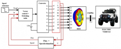
εp is the tolerated error in dB. The simulation of this method in a Matlab environment for different values of α was carried out. The transfer function that we have chosen for the present control system is for α=0.62. Figure 14 shows a sensor-less block diagram vector control for SRM 8/6 poles using fractional controllers with DTC.
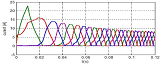
In our simulation using the Matlab/Simulink, we compared the system with the ANN controller and the system with the fractional-order controller under the same constraints of the motor whose specifications as shown in Table 5. Figure 15 depicts the currents obtained for the four phases at the output of the inverter based on the proposed block diagrams shown in Figure 13 and Figure 14.
Table 5. Specifications of the SRM
|
Designation |
Notation |
|
Phases |
4 |
|
Stator pole number |
8 |
|
Rotor pole number |
6 |
|
Rated voltage |
230 V |
|
Rated current |
10A |
|
Rated speed |
4000 rpm |
|
Rated load |
0.75 kW |
|
Moment of inertia (Jm) |
0.005 Kg-m3 |
|
Viscous friction |
0.005 Nm/(rad/s) |
Figure 14. Sensorless block diagram for vector control of SRM 8/6 using Fractional Regulators with DTC
Figure 15. Output current waveform of SRM 8/6
Figure 16. Waveform speed result of SRM8/6 with ANN controller
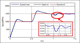
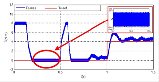
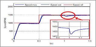
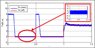
The results of the simulation model with the ANN control system and the fractional-order control PIα are respectively shown in Figure 16; Figure 17; Figure 18, and Figure 19. To better understand the behavior of SRM8/6, we triggered the test at the instant t=0.5s under a load of 4N.m with a speed change from 1000rpm to 1500rpm. The fractional order controller performed admirably, and the speed trajectory is satisfactory. In the ANN control case, however, the overshoot is significant (see Figure 16, and Figure 17). The simulation also shows that with the fractional order controller PIα the torque oscillations are much better than for the ANN control case (Figure 18, and Figure 19). These results demonstrate the superiority of the fractional PIα controller under unpredictable overload conditions.
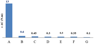
After simulating the blocks in the Matlab/Simulink environment for two intelligent controllers associated with the DTC, respectively the ANN control system and the fractional-order control PIα, we have compared the obtained results with the recent works mentioned above and shown in Table 6 and Figure 20. We concluded that:
- By designing DTC and with different types of controllers, ranging from a simple PI to intelligent controllers such as FLC, ANN, and PIα, the torque undulations are reduced.
- The torque ripple rate obtained from each technique was analyzed. It is concluded that the direct DTC torque control method with fractional-order PIα gives at least the best results with torque Ripples.
In Figure 20 corresponding to Table 6, the results obtained have been compared to recent related works, cited at the beginning of this article. The ripples of the torque which are at the origin of the vibrations of the SRM are markedly lower (cases F and G).
Figure 17. Waveform torque results of SRM8/6 with ANN controller
Figure 18. Waveform speed result of SRM8/6 with PIα controller
Figure 19. Waveform torque results of SRM8/6 with PIα controller
Table 6. Comparative table of results obtained with those found in recent reviews
|
CASE |
TECHNIQUES USED |
± ΔC (N.m) |
|
A |
Without any controller [1] |
13 |
|
B |
PI controller [2] |
0,6 |
|
C |
DTC with simple PI [3] |
0,45 |
|
D |
DTC with Fuzzy logic control [4] |
0,3 |
|
E |
DTC ANN [5] |
0,3 |
|
F |
DTC with ANN in the present work |
0,35 |
|
G |
DTC with Fractional-order in the present work |
0.1 |
Figure 20. Diagram of the comparison of the results obtained with those found in the recent reviews
The use of direct torque control significantly improves the behavior of the SRM8/6, particularly the torque response by significantly reducing these undulations caused primarily by the rotor's peripheral shape. The DTC appears to be well suited to the SRM8/6 because it is sensor-less, and with better precision to overcome load constraints of the driven system. The response seems even more improved if we associate the DTC with a fractional order controller.
The comparison between the use of ANN regulator and the PIα regulator shows the importance of the latter, which offers better stability in dynamic mode, a speed without overshoot, and better behavior to load disturbances, which increases the machine longevity and robustness compared to those obtained with ANN controller.
The future direction of our work is oriented towards the use of SRMs as electric drive motors for heavy vehicles, excavation machinery, loading, and transport machinery in underground mines to overcome the problems of atmospheric pollution, fight against occupational diseases produced by diesel fuel, improve the living conditions of personnel working hundreds of meters underground, where breathing is even made by artificial ventilation and consequently reduce the cost of ore by using exclusively electrical energy produced in the best case by a renewable energy station (solar or wind) specific to the mine.
[1] Warpatkar, P.S., Dalvi, H.S, (2016). A new approach for minimization of torque ripple in 8/6 switched reluctance motor. International Research Journal of Engineering and Technology (IRJET), 3(3): 81-85.
[2] Nagesh, K., Lenine, D., Sujatha, P. (2020). Modelling and analysis of 8/6 switched reluctance motor with PI controller. Journal of Mechanics of Continua and Mathematical Sciences, 5: 357-370. https://doi.org/10.26782/jmcms.spl.5/2020.01.00029
[3] Pratapgiri, S., Narsimha, P.P.V. (2012). Direct torque control of 4 phases 8/6 switched reluctance motor drive for constant torque load. World Journal of Modelling and Simulation, 8(3): 185-195.
[4] Ghani, M.R.A., Farah, N., Tamjis, M.R. (2016). Vector control of switched reluctance motor using fuzzy logic and artificial neutral network controllers. International Conference on Electrical, Electronics, and Optimization Techniques (ICEEOT), pp. 4412-4417. https://doi.org/10.1109/ICEEOT.2016.7755553
[5] Shrivastava, K. (2015). Vector control of switched reluctance motor 8/6 using fuzzy logic controller. International Journal of Electrical Engineering & Technology (IJEET), 6(8): 99-107.
[6] Xue, X.D., Cheng, K.W.E., Cheung, N.C. (2009). Selection of electric motor drives for electric vehicles. Australasian Universities Power Engineering Conference, 170: 1-6. http://hdl.handle.net/10397/52217
[7] Zaharia, M.V. (2016). Contributions to the study of Switched reluctance machine for automotive integrated starter-alternator application. Doctoral thesis, Ecole Centrale de Lille, France.
[8] Srinivas, P., Prasad, P.V.N, (2011). Torque ripple minimization of 4 phases 8/6 switched reluctance motor drive with Instantaneous Torque Control. International Journal on Electrical Engineering and Informatics, 3(4): 488-497. https://doi.org/10.15676/ijeei.2011.3.4.8
[9] Lawrenson, P.J., Stephenson, J.M., Blenkinsop, P.T., Corda, J., Fulton, N. (1980). Variable speed switched reluctance motors. IEE Proceedings B, Electric Power Applications, 27(4): 253-265. https://doi.org/10.1049/ip-b.1980.0034
[10] Miller, T.J.E. (1993). Switched reluctance motors and their control. Magna Physics Pub Clarendon Press, Oxford, 0198593872.
[11] Dong, F., Chen, H., Xu, S., Cui, S. (2020). A fault-tolerant sensorless position estimation scheme for switched reluctance motor at low speed. International Journal for Computation and Mathematics in Electrical and Electronic Engineering, 39(4): 65-80. https://doi.org/10.1108/compel-08-2019-0307
[12] Boufadene, M., Belkheiri, M., Rabhi, A. (2018). Adaptive nonlinear observer augmented by radial basis neural network for a nonlinear sensorless control of an induction machine. International Journal of Automation and Control, 12(1): 27-43. https://doi.org/10.1504/IJAAC.2018.088600
[13] Abdel-Fadil, R., Szamel, L. (2018). Fuzzy logic current control of switched reluctance motor for electric vehicles applications. International Journal of Engineering and Information Systems (IJEAIS), 2(4): 19-28.
[14] Kushwaha, A., Kanagaraj, R. (2020). Peak-current estimation using a simplified current-rise model of switched reluctance generator operating in single-pulse mode. International Journal of Electrical Power & Energy Systems, 120(105971). https://doi.org/10.1016/j.ijepes.2020.105971
[15] Srihari, T., Jeyabaharath, R., Veena, P. (2016). An improved direct torque control using intelligent technique for switched reluctance motor drive. South Asian Journal of Engineering and Technology, 2(16): 125-133.
[16] Mahalakshmi, G., Ganesh, C. (2018). A review of torque ripple control strategies of switched reluctance motor. International Journal of Applied Engineering Research, 13(7): 4688-4692.
[17] Ma, M., Chang, Z., Hu, Y., Li, F., Gan, C., Cao, W. (2018). An integrated Switched Reluctance Motor drive topology with voltage-boosting and on-board charging capabilities for plug-in hybrid electric vehicles (PHEVs). IEEE, Access, 6: 1550-1559. https://doi.org/10.1109/ACCESS.2017.2779460
[18] Khan, Y.A., Verma, V. (2019). Novel speed estimation technique for vector-controlled switched reluctance motor drive. IET Electric Power Applications, 13(8): 1193-1203. https://doi.org/10.1049/ietepa.2018.5572
[19] Korkmaz, F. (2017). Speed and torque control of an induction motor with ANN based DTC. International Journal of Instrumentation and Control Systems (IJICS), 7(1): 15-24. https://doi.org/10.5121/ijics.2017.7102
[20] Kumar, R.S., Vasanth, J.A. (2013). Intelligent neuro-controller based on speed and torque control of five phase switched reluctance motor. Information Communication and Embedded Systems (ICICES) 2013 International Conference, pp. 966-973. https://doi.org/10.1109/ICICES.2013.6508296
[21] Rajesh, P.V., Balamurugan, M., Ramaiah, N. (2019). Artificial neural network based on direct torque control of four phases switched reluctance motor. SSRN Electronic Journal. https://dx.doi.org/10.2139/ssrn.3371369
[22] Viswanathan, P., Thathan, M. (2016). Torque ripple minimization of direct torque controlled four-phases switched reluctance motor using artificial intelligent controller. World Journal of Modelling and Simulation, 12(3): 163-174.
[23] Podlubny, I. (1999). Fractional-order systems and PID-controller. IEEE Transactions on Automatic Control, 44(1): 208-214. https://doi.org/10.1109/9.739144
[24] Ghoudelbourk, S., Dib, D., Omeiri, A., Taher, A.A. (2016). MPPT control in wind energy conversion systems and the application of fractional control (PIα) in a pitch wind turbine. International Journal of Modelling, Identification and Control, 26(2): 140-151. https://doi.org/10.1504/IJMIC.2016.078329
[25] Ardeshiri, R.R., Kashani, H.N., Reza-Ahrabi, A. (2019). Design and simulation of self-tuning fractional order fuzzy PID controller for robotic manipulator. International Journal of Automation and Control, 13(5): 595-618. https://doi.org/10.1504/IJAAC.2019.101912
[26] Neçaibia, A., Ladaci, S. (2014). Self-tuning fractional-order PIλDµ controller based on extremum seeking approach. International Journal of Automation and Control, 8(2): 99-121. https://doi.org/10.1504/IJAAC.2014.063361
[27] Charef, A., Sun, H.H., Tsao, Y.Y., Onaral, B. (1992). Fractal system as represented by singularity function. IEEE Transactions on Automatic Control, 37(9): 1465-1470. https://doi.org/10.1109/9.159595
[28] Bai, D.Y., Wang, C.Y., Zou, J. (2015). Design and simulation of fractional order control systems based on bode’s ideal transfer function. International Journal of Control and Automation, 8(3): 1-8. http://dx.doi.org/10.14257/ijca.2015.8.3.01