Sami Muhsen*![]() | Hussein K. Halwas
| Hussein K. Halwas![]() | Mohsin O. Al-Khafaji | Abdulkareem A. Waha
| Mohsin O. Al-Khafaji | Abdulkareem A. Waha![]() | Esam M. Mohamed
| Esam M. Mohamed![]()
© 2025 The authors. This article is published by IIETA and is licensed under the CC BY 4.0 license (http://creativecommons.org/licenses/by/4.0/).
OPEN ACCESS
This study investigates the thermal performance of evaporators in vapour compression refrigeration systems, with a focus on the design, experimental analysis, and impact of various operating parameters. The evaporator used in the experiments was tested in the Air Condition Laboratory at Al-Mustaqbal University, with key specifications including a total tube length of 19.2 meters, tube diameter of 7 mm, and fin geometry configured for optimal heat transfer. The experimental setup included measuring the evaporator's performance under various conditions, specifically with refrigerant R-22. The average evaporator temperature was maintained at 5℃, with the refrigerant entering at -1.6℃ and exiting at 3.6℃. The pressure within the evaporator was recorded at 584 kPa, while the condenser operated at 40℃ and 1533.5 kPa. Key thermodynamic parameters, such as the overall heat transfer coefficient (0.466 kJ/m²·s·℃ for copper), were calculated and analyzed. Key findings from the experiments include a direct relationship between the evaporator's area and its cooling capacity, as expressed by the equation Q=U×Θm×A. Additionally, it was observed that the refrigeration capacity increases with the temperature difference between the refrigerant and the air. The study also found that the coefficient of performance (COP) of the refrigeration cycle improves with an increase in the evaporator's effect, though it decreases as the evaporator temperature rises. The study concludes that the presence of lubricating oil within the system complicates heat transfer and pressure drop, making the thermal design of the evaporator challenging. Furthermore, it was determined that high-pressure refrigerants enhance evaporator capacity, and the heat transfer capacity is significantly influenced by the temperature differential between the refrigerant and the medium being cooled. The findings contribute to a better understanding of evaporator design and optimization for improved system performance.
evaporator, heat transfer coefficient, finned tubes, evaporation
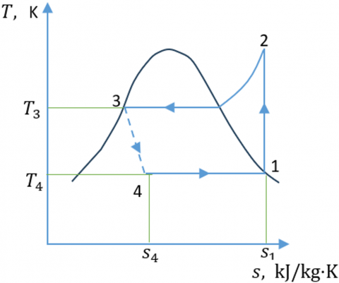
The optimal vapour compression cycle, illustrated in Figure 1, consists of four primary components: the evaporator, compressor, expansion valve, and condenser. Vapour compression refrigeration systems represent an advanced iteration of air refrigeration, utilizing a suitable refrigerant to facilitate the process [1].
The evaporator is an essential element on the low-pressure side of a refrigeration system. It receives liquid refrigerant from the expansion valve, which then undergoes a phase change to vapour. The primary function of the evaporator is to extract heat from a space or medium to achieve cooling. For effective heat transfer, the boiling refrigerant within the evaporator must consistently maintain a lower temperature than the surrounding medium.
The evaporator cools down and maintains its low temperature due to two primary factors: (1) the refrigerant circulating within the coil is at a low temperature, which consequently cools the evaporator coil itself, and (2) as the refrigerant undergoes boiling (phase changing from liquid to vapour), the absorbed heat is converted into latent heat, allowing the refrigerant to sustain its low temperature throughout the process.
As shown in Figure 2(a) at point 3, the saturation temperature corresponding to the refrigerant's condensing pressure is generally lower than the temperature at which the refrigerant is sub-cooled to a liquid state. This is done to enhance the cooling efficiency. The degree of sub-cooling is influenced by the coolant temperature during condensation, along with the design and capacity of the condenser [1].
(a)
(b)
Figure 1. Ideal vapour compression cycle: (a) T-S diagram, (b) p-h diagram [1]
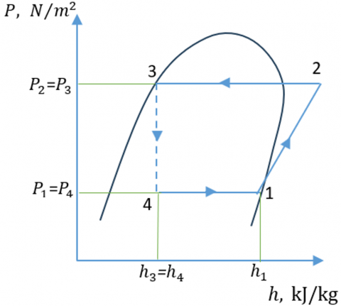
(a)
(b)
Figure 2. (a) Subcooling and (b) superheating [1]
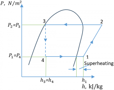
2.1 Superheating
Superheating is utilized to prevent compressor lagging, which can lead to expensive repairs. As depicted in Figure 2(b), the level of superheat generated is primarily influenced by the refrigerant supply, as well as the design of the compressor and evaporator.
2.2 Working of an evaporator
The evaporator cools down and stays cold for two main reasons:
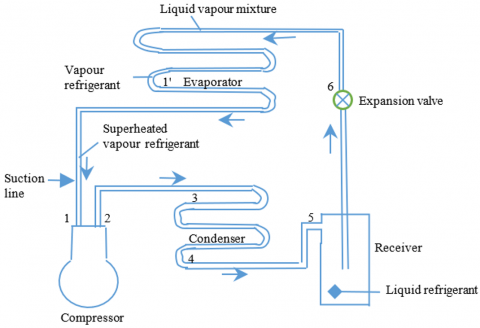
The operation of an evaporator can be most effectively understood by examining a basic refrigeration system, as illustrated in Figure 3(a). The corresponding (p-h) diagram is shown in Figure 3(b) [2].
(a) Schematic diagram of a simple refrigerating system
(b) P-h diagram of a simple refrigeration system
Figure 3. Schematic diagram and p-h diagram of a simple refrigerating system [2]
When operating under optimal conditions, the liquid phase refrigerant is sub-cooled, meaning it is cooled below its saturation temperature. This sub-cooling guarantees that only pure liquid refrigerant, free of any vapor, approaches the expansion valve, allowing for unrestricted refrigerant flow through the valve.
The liquid refrigerant at low pressure enters the evaporator at point 6, as liquid refrigerant passes through the evaporator coil, it continually absorbs heat through coil walls, from the medium being cooled. During this, the refrigerant continues to boil and evaporate.
At point 1´, the entire liquid refrigerant has fully evaporated, leaving only vapour in the evaporator coil. At this stage, the refrigerant has exhausted its capacity to absorb heat through the phase change process [3].
As the vapour refrigerant at point 1´ remains cooler than the substance being cooled, it continues to absorb heat from the surrounding medium.
This heat absorption leads to a rise in the sensible heat (i.e., temperature) of the vapour refrigerant. The vapour temperature keeps increasing as it moves through the evaporator until it reaches the suction line at point 1. At this stage, the vapour’s temperature exceeds its saturation temperature, indicating that the refrigerant is now in a superheated state [4].
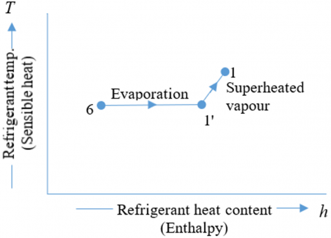
Figure 4 illustrates how the refrigerant’s temperature (sensible heat) and heat content (enthalpy) change throughout the evaporator. It demonstrates that during the phase change from point 6 to point 1´ the refrigerant temperature remains constant while the enthalpy increases steadily. This indicates that latent heat is absorbed by the liquid refrigerant as it evaporates, without any temperature change. From point 1´ to point 1, both the temperature and enthalpy of the refrigerant rise, signifying the addition of sensible heat to the vapour. At point 1, the refrigerant has fully evaporated. The segment from 1´ to 1 represents the increase in sensible heat of the vapour phase [5].
Figure 4. T-h diagram of a simple refrigerating system [6]
2.3 Capacity of an evaporator
An evaporator's capacity is defined as the quantity of heat it takes in during a certain time interval. The heat it absorbs, also referred to as its heat transfer capacity, is calculated by:
Q=U A (T2 - T1) watt
U - Overall heat transfer coefficient in W/m2 K.
A - Area of evaporator surface in m2.
T2 - Temperature of medium to be cooled in K.
T1 - Saturation temperature of refrigerant at evaporator pressure in K.
2.4 Finned-tube evaporator
The finned-tube and shell-type evaporators are among the most commonly utilized designs. As illustrated in Figure 5, the finned-tube evaporator is composed of bar tubes or coils, to which steel plates, or fins, are attached [7].
Figure 5. Direct expansion finned tube evaporator [7]
The metal fins are fabricated from thin sheets known for their high thermal conductivity. The heat transfer rate can be optimized for specific applications by modifying the fins' shape, size, or spacing. Finned evaporators, also referred to by various names, are characterized by their extended surface area, which significantly enhances the heat transfer contact area. As air passes through the coil and comes into contact with the cool surfaces of the fins, heat is transferred to the refrigerant, causing it to boil and exit the evaporator as vapour. The fins also induce air turbulence as it flows over them, improving heat transfer by minimizing stratification in the airstream exiting the coil, as depicted in Figure 6 [8].
Figure 6. Turbulent flow at finned tubes [8]
Each refrigerant distributor operates within a defined safe range, determined by the allowable flow rates of refrigerant. When the evaporator coil is extended, multiple distributors may be employed to ensure an even supply of liquid refrigerant to the coil [9].
The superheating region within the final section of the tubes ensures that the refrigerant vapour is entirely devoid of liquid before it reaches the compressor. This is achieved by maintaining a temperature difference between the refrigerant and the surrounding air that exceeds the air's boiling point [10].
To ensure complete vaporization of the liquid refrigerant, the expansion valve is commonly used to control the amount of refrigerant flowing through the evaporator. When compressors are unloaded or cycled, the expansion valve allows for adjustment of the evaporator's capacity to match the system's load, as illustrated in Figure 7 [8].
Finned evaporators are particularly advantageous for refrigeration systems operating above 0 degrees Celsius [11]. Their rapid heat transfer capabilities enable automatic defrosting during the off cycle, when the coil temperature approaches the freezing point. It is crucial to prevent frost accumulation between the fins, as this can significantly reduce the efficiency of the evaporator [12].
Figure 7. Finned-tube evaporator control [8]
To minimize the risk of icing, air conditioning coils are designed to operate at the highest possible suction temperatures, with fin spacing kept as narrow as a few millimeters. In systems where the coils are expected to freeze during the cooling cycle and then thaw during the off cycle, the fin spacing is typically wider. The overall efficiency of the evaporator is enhanced by these fins, which serve to increase the external surface area of the device, thereby improving heat transfer capabilities [8].
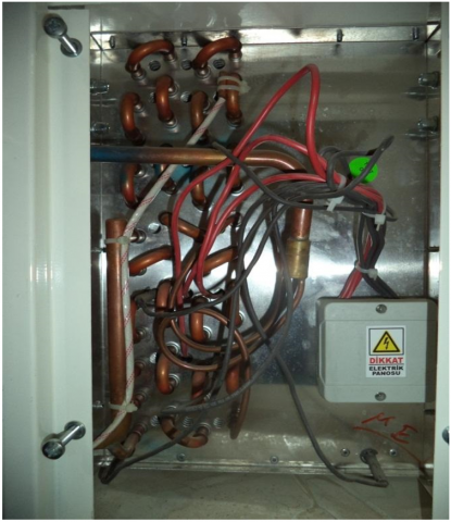
A rapid-response thermometer is strongly recommended. It should be positioned at the evaporator intake and as close as possible to the thermal element or bulb of the expansion valve. These thermometers must be securely attached to the pipework, which should be free of frost or ice to ensure optimal thermal conductivity, as illustrated in Figure 8. This setup allows for swift and accurate measurement of the refrigerant temperature as it traverses the piping system [13].
Figure 8. Expansion valve and probes
The extent of superheating within the evaporator is directly related to the temperature difference between the two measurement points. It is essential to adjust the expansion valve to achieve the correct level of superheating during commissioning, following a replacement, and as a safety measure after the system has been charged [14, 15].
The thermostatic expansion valve functions correctly only when the thermal bulb is optimally positioned. In a chilled area, the bulb should be securely fastened to a horizontal section of the suction line near the evaporator outlet. As shown in Figure 8, the entire length of the bulb must maintain a strong thermal connection with the piping [16].
2.5 Valve settings
Manufacturers typically specify the settings for new expansion valves, which are generally adjusted to maintain a superheat range of 3.5 to 5℃. Different types of evaporators require distinct valve settings to ensure proper coil flooding. Optimal operating conditions are achieved when thermostatic expansion valves are set within the following ranges:
If a factory-set valve with a 7℃ setting is installed on a forced air evaporator, excessive superheating will occur. By adjusting the valve to an appropriate range, such as 4℃, the amount of superheating will be reduced, resulting in a more efficient evaporator. Figure 9 shows the refrigerant conditions in a gravity coil at different expansion valve settings [9].
Figure 9. Expansion valve settings [9]
2.6 Boiling tubes inside
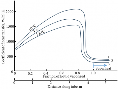
Predicting the heat transfer coefficient is challenging because of the complexity of the boiling process, which is influenced by factors such as surface tension, saturation temperature, and the material properties, along with the effects of latent heat [17, 18]. The boiling process is governed by two primary mechanisms: Pool boiling, as observed in flooded evaporators, and flow boiling or forced convection, as seen in direct expansion evaporators [19]. As the refrigerant boils within the tubes, there is a gradual change in the heat transfer coefficient. Initially, a small amount of vaporized refrigerant enters the evaporator tubes. As the vapour fraction increases, the heat transfer coefficient also rises. However, once nearly all the refrigerant has evaporated, the coefficient decreases to a value associated with heat transfer by forced convection in the vapour phase. Figure 10 illustrates the local heat transfer coefficients at three different temperatures along the entire length of the tube. The highest heat transfer occurs at the maximum evaporating temperature, likely because a larger portion of the metal surface remains wetted by liquid under these conditions, due to the higher vapour density at these temperatures and pressures [20, 21].
Figure 10. Heat transfer coefficients of refrigerant R-22 boiling inside tubes [20]
2.7 Experimental work
The evaporator of an air conditioning unit was tested in the Air Conditioning Laboratory at Al-Mustaqbal University, as shown in Figures 11 and 12.
Figure 11. Air conditioning equipment in the air condition laboratory
Figure 12. Pipes connections of evaporator
Details about the evaporator in the laboratory are provided in Table 1.
Table 1. The specifications of laboratory evaporator
| No. |
Items |
Unit |
Value |
| 1 |
Tube length |
mm |
400 |
| 2 |
Total Tube length |
m |
19.2 |
| 3 |
Tube diameter |
mm |
7 |
| 4 |
Number of pipes |
- |
48 |
| 5 |
Tube row spacing |
mm |
22 |
| 6 |
Number of tubes per row |
- |
12 |
| 7 |
Number of Fins |
- |
68 |
| 8 |
Fin long (b) |
mm |
90 |
| 9 |
Fin width (w) |
mm |
60 |
| 10 |
Fin geometry |
- |
Louver |
2.8 The thermodynamics design of evaporator
After calculating various thermodynamic parameters of the cycle, the results were compiled and are presented in Table 2.
Table 2. The calculated thermodynamic parameters of the cycle
|
No. |
Item |
Value |
No. |
Item |
Value |
|
1 |
T1 |
5℃ |
2 |
P1 |
584 kPa |
|
3 |
h1 |
406.8 kJ/kg |
4 |
S1 (Sg) |
1.744 kJ/kg·k |
|
5 |
T1 |
40℃ |
6 |
P2 |
1534 kPa |
|
7 |
h2 |
416.2 kJ/kg |
8 |
S2(Sg) |
1.744 kJ/kg·k |
|
9 |
T3 |
40℃, |
10 |
P3 |
1534 kPa |
|
11 |
h3(hf) |
249.6 kJ/kg.k |
12 |
S3(Sf) |
1.166 kJ/kg·k |
|
13 |
T4 |
5℃, |
14 |
P4 |
584 kPa |
|
15 |
h4(hf) |
205.9 kJ/kg |
16 |
S4(Sf) |
1.021 kJ/kg·k |
|
17 |
X1 |
0.936 |
18 |
$h_1^{-}$ |
367.56 kJ/kg |
|
19 |
X4 |
0.2 |
20 |
$h_4^{-}$ |
246.08 kJ/kg |
|
21 |
ṁ |
0.0577 kg/s |
22 |
Wc |
2.8 kw |
|
23 |
COP |
2.5 |
24 |
A |
0.79 m² |
|
25 |
Өm |
20.78℃ |
26 |
Q |
7.65 kw |
|
27 |
ṁa |
0.95 kg/s |
28 |
U |
1680 kJ/hr·m²·℃ |
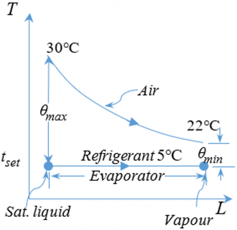
Figure 13. The (T–L) diagram for heat transfer
Figure 13 illustrates the temperature versus latent heat (T–L) diagram for heat transfer to the air.
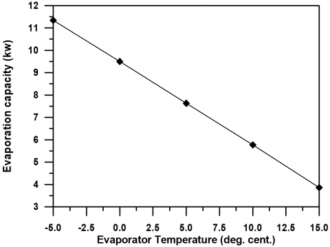
The relationship between refrigeration capacity (Q in kW) and evaporator area (A in m²) is depicted in Figure 14. The refrigeration capacity, Q, is directly related to the evaporator area, increasing as the area increases, as described by the equation: Q=U×Θm×Am, where the evaporator is responsible for absorbing heat from the targeted space. In other words, with a larger evaporator area, assuming the overall heat transfer coefficient (U) and the temperature difference between the refrigerant and the air (Θm) remain constant, the more heat the evaporator can absorb, which increases the system’s capacity. However, an oversized evaporator can lead to a reduction in evaporator performance, as seen in Figure 15, due to the rise in evaporator temperature. This reduction can be mitigated by increasing the refrigerant’s mass flow rate and improving heat transfer conditions. This scenario requires optimization, which will be addressed in a future study.
Figure 14. The relationship between refrigeration capacity and the area of the evaporator
Figure 15. Correlation between the rate of evaporation and evaporation temperature
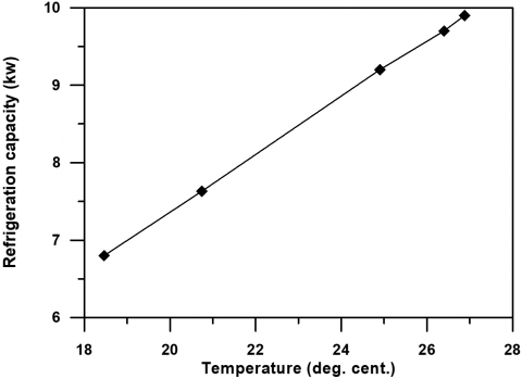
Figure 16 illustrates that refrigeration capacity increases with the log mean temperature difference (LMTD, Θm). This temperature difference is influenced by the inlet air temperature (T1). As shown in the figure, a higher inlet air temperature leads to a higher refrigeration capacity. In other words, a higher inlet air temperature results in more heat being absorbed in the evaporator, that consequently increases the compressor load (higher suction pressure) and pushes the system closer to its operational limits. Conversely, lower inlet air temperatures result in less heat absorption, that reducing the compressor load (low suction pressure) and increasing the risk of evaporator freezing.
Figure 17 shows the coefficient of performance (COP) increases as the evaporator effect increases. This relationship can be observed by examining the evaporator temperature and the compressor load. A higher evaporator temperature leads to a higher COP, indicating better system efficiency, while also reducing the compressor workload.
Figure 16. The relationship between refrigerant capacity and the temperature of the inlet air
Figure 17. Relationship between the COP and evaporation effect
This study presents a comprehensive experimental investigation into the thermal performance of a finned-tube evaporator used in vapor compression refrigeration systems. The findings confirm that several factors including evaporator area, refrigerant temperature, inlet air temperature, and refrigerant flow rate significantly influence the system’s cooling capacity and efficiency.
The results demonstrate a direct relationship between the evaporator area and its cooling capacity; increasing the surface area enhances heat absorption, provided other parameters remain optimal. Similarly, a higher log mean temperature difference (LMTD) leads to greater heat transfer and improved refrigeration capacity. The coefficient of performance (COP) was shown to increase with a higher evaporator temperature, resulting in reduced compressor workload and improved overall system efficiency.
However, the presence of lubricating oil and frost formation presents challenges to optimal heat transfer. The study also highlights that high pressure refrigerants and precise control of expansion valve settings are critical to maintaining effective superheating and preventing compressor damage.
| A |
surface area, m² |
| L |
tube length, m |
| W |
fin width, mm |
| H |
enthalpy, kJ/kg |
| S |
entropy |
| $\dot{\mathrm{m}}$ |
mass flow, kg/s |
| $\mathrm{W}_{\mathrm{c}}$ |
work compressor, kw |
| $\Theta \mathrm{m}$ |
LMTD, ℃ |
| D |
tube diameter, m |
| B |
fin long, mm |
| P |
pressure, N/m² |
| T |
temperature, ℃ |
| X |
dryness fraction |
| Q |
evaporation capacity, kw |
| COP |
coefficient of performance |
| U |
heat transfer coefficient |
[1] Wang, S.K. (2000). Handbook of Air Conditioning and Refrigeration, Second Edition. McGraw–Hill.
[2] Hannure, A.O., Patil, A.M. (2014). Design & Development of combined unit for Air-conditioning & Refrigeration and simulation of system. International Journal of Advanced Research in Science and Engineering (IJARSE), 3(12): 43-52.
[3] Abdalla, K.N., Mohamed, E.T.H. (2013). Effect of dust and particular matter on evaporator coil performance. University of Khartoum Engineering Journal (UofKEJ), 3(2): 30-34.
[4] Ritesh, K., Vijayanand, P., Kumar, N.V. (2015). Thermal analysis on evaporator tube of 1.5 ton air conditioning using AL99 (1100) material. International Journal of Current Engineering and Technology, 5(5): 3242-3245.
[5] Jadhav, S.S., Mali, K.V. (2014). Evaluation a refrigerant R410A as substitute for R22 in window air conditioner. IOSR Journal of Mechanical and Civil Engineering (IOSR JMCE), pp. 23-32.
[6] Khurmi, R.S., Gupta, J.K. (2012). A Textbook of Refrigeration and Air Conditioning. 5th Revised Edition, New Delhi-110055.
[7] Haripur, T. (2012). Condensers & Evaporators. Version 1 ME.
[8] TRANE. (2016). Evaporator / Period Three. TRG–TRCO5– EN / Notes.
[9] Pan, Y., Lorente, S., Bejan, A., Xia, L., Deng, S. (2014). Distribution of size in multi-evaporator air conditioning systems. International Journal of Energy Research, 38(5): 652-657. https://doi.org/10.1002/er.3072
[10] Luyben, W.L. (2019). Control of compression refrigeration process with superheat or saturated boiling. Chemical Engineering and Processing-Process Intensification, 138: 97-110. https://doi.org/10.1016/j.cep.2019.03.005
[11] Alhamdo, M.H., Theeb, M.A., Abdulhamed, J.J. (2018). Performance improvement of an air- conditioning system during refrigerant evaporation. Journal of Engineering and Sustainable Development, 22(6): 101-113. https://doi.org/10.31272/jeasd.2018.6.9
[12] Kharagepur. Vapour compression refrigeration systems: Performance aspects and cycle modifications. Version 1 ME, Lesson 11, National Digital Library of India. http://ndl.iitkgp.ac.in/he_document/nptel/nptel/11 2105129_pdf_rac_lecture_11.
[13] Laidlaw, G. (2020). Proper positioning of TEV bulb. RACA Journal. https://refrigerationandaircon.co.za/proper-positioning-of-tev-bulb/?utm_source=chatgpt.com.
[14] Chen, W., Chen, Z.J., Zhu, R.Q., Wu, Y.Z. (2002). Experimental investigation of a minimum stable superheat control system of an evaporator. International Journal of Refrigeration, 25(8): 1137-1142. https://doi.org/10.1016/S0140-7007(01)00107-4
[15] Bopray, A., Downer, R., Ward, K. (2025). Understanding expansion valves in HVAC systems. https://todayshomeowner.com/hvac/guides/what-are-expansion-valves/, accessed on Jul. 30, 2025.
[16] AL-Rashed, A.A.A.A. (2011). Effect of evaporator temperature on vapour compression refrigeration system. Alexandria Engineering Journal, 50(4): 283-290. https://doi.org/10.1016/j.aej.201 0.08.003
[17] Patil, A.P., Vittala, V.C.B. (2005). Surface energy effect on boiling heat transfer. Heat Mass Transfer, 41: 1043-1047. https://doi.org/10.1007/s00231-005-0639-4
[18] Colombo, L.P.M., Licchini, A., Phan, N.T., Molinaroli, L. (2020). Saturation temperature effect on heat transfer coefficient during convective boiling in microfin tubes. Journal of Physics Conference Series, 1599(1): 012052. https://doi.org/10.1088/1742-6596/1599/1/012052
[19] Clearing House, Energy Efficiency and Renewable Energy. (1999). Energy-Efficient Air Conditioning. Department of Energy (DOE)/GO-10099-379 FS 206, June 1999. https://www.nrel.gov/docs/fy99osti/17467.pdf.
[20] Stoecker, W.F., Jones, J.W. (2002). Refrigeration And Air Conditioning. Second Edition, McGraw–Hill, Inc. https://www.scribd.com/document/436491549/Refrigeration-and-Air-Conditioning-2nd-Edition-W-F-Stoecker-J-W-Jones-pdf.
[21] Maheshwari, M., Sharivastava, G., Choubey, B. (2019). Study on refrigeration system designed for low temperature. International Journal of Scientific and Research Publication, 3(2): 1-3.