© 2018 IIETA. This article is published by IIETA and is licensed under the CC BY 4.0 license (http://creativecommons.org/licenses/by/4.0/).
OPEN ACCESS
In this work, we consider a single relay multiple input multiple output (MIMO) space-time block-code (STBC) based relaying system for two strategies using transmit antenna selection (TAS) technique. We consider the Rayleigh distribution between source to destination (SD), relay to destination (RD) and source to relay (SR) fading channel links. In first selection strategy, we consider selective decode and forward (SDF) protocol between the relay and destination and in second selection strategy, we consider STBC SDF protocol between RD fading channel links. We derive the closed form expressions for SER, SER upper bound and diversity order (DO). The optimal power allocation factors (OPFs) are derived for the both strategies, which minimize the SER of the relaying system. Simulation results show that the second strategy performs better than the first one for the same DO.
multiple input multiple output, space- time-block- code, selective decode and forward, pairwise error probability
MIMO is proven, cost-effective technology, high spectral efficiency, provides antenna diversity and reduces channel fading. Cooperative communication attains ominously high data rates in 4G/5G communication systems due to their ability to create a virtual array of antennas (Ibrahim et al., 2008). With increasing emphasis on Femto, small and Pico cell networks, cooperative systems are a promising solution for 5G systems. The most famous relaying protocols are amplify-and-forward (AF), decode-and-forward (DF) and SDF protocols (Khattabi and Matalgah, 2015; Ryu et al., 2018; Shankar et al., 2017; Shankar et al., 2017). Also by using MIMO and STBC together, better end-to-end error performance has been achieved and it will enhance the data transmission rate.
In references (Varshney and Puri, 2017; Varshney et al., 2015), the author analyzed the pairwise error probability (PEP) of MIMO STBC S-DF cooperative communication protocol. The authors derived the closed-form PEP expressions for dual phase and multiple phase cooperation protocol, derive the DO and OPFs.
In the works (Amarasuriya et al., 2011; Yang et al., 2014), the authors investigated TAS based cooperation network. In stduy (Amarasuriya et al., 2011), AF based relaying is investigated and it is shown that two sub-optimal TAS technique achieves DOs MD+MRmin andM_{R}+M_{S} M_{D}. In sdudy (Yang et al., 2014), TAS for full duplex AF relaying protocol is extensively investigated.
In study (Krishna and Bhatnagar, 2014), the author investigated the symbol error rate (SER) performance of two sub-optimal TAS strategies having only one relay SDF cooperation network. Closed form and upper bound expressions of SER for SDF systems have been taken for both TAS strategies.
In study (Krishna and Bhatnagar, 2016), the authors investigated the single-relay MIMO DF relaying network with M_{S}, M_{R} and M_{D} number of antennas are employed in source, relay and destination. In sudy (Jin and Shin, 2013), the authors offered the selection of a new source transmit antenna based on the channel state information. It is shown that source transmit antenna selection achieves the full DO of M_{S} M_{D}+M M_{R} \min \left(M_{S}, M_{D}\right). In study (Halber and Chakravarty, 2018), the author has investigated the relay for the optimization purpose.
In this paper, investigation of the single relay MIMO STBC based SDF system employing M-ary PSK by deriving the closed form PEP expressions and PEP upper bounds has been done. The closed form SER expression for two sub-optimal selection strategies has been derived. There are consideration two criteria for antenna selection 1) Maximization of SNR of SD and RD fading channel links and 2) Maximization of SNR of RD and SR fading channel links. Also, we investigated the DO and optimal power allocation.
In this paper, section 2 gives the System Model. Section 3, describes SER analysis. Section 4, shows the Simulation results and discussions. Section 5 provides the conclusion for our proposed method.
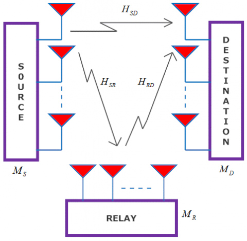
Consider a MIMO SDF cooperative communication system employing single relay, as given in Figure 1. The relay, source, and destination nodes are employed with MR, MS and MD number of antennas, respectively. Only in the case of successful decoding relay node, the signal will be forwarded to the destination node, otherwise it will be inactive state. Let H_{S R} \in \mathbb{C}^{M_{R} M_{S}}, H_{S D} \in \mathbb{C}^{M_{D} M_{S}} and H_{R D} \in \mathbb{C}^{M_{D} M_{R}} denote the channel matrix from SR, SD and RD respectively. Let h_{d_{i} s_{j}} \in H_{S D}, h_{r_{i} s_{j}} \in H_{S R} andh_{d_{i} r_{j}} \in H_{R D} denote the channel coefficients for SD, SR and RD fading links. The channel coefficient is modeled as the zero mean complex Gaussian circular shift (ZMCGCS) random variable (RV) with unit variance. Let \mathbb{Q}_{d_{i} r_{j}}=\left|h_{d_{i} r_{j}}\right|^{2}, \mathbb{Q}_{r_{i} s_{j}}=\left|h_{r_{i} s_{j}}\right|^{2} and \mathbb{Q}_{d_{i} s_{j}}=\left|h_{d_{i} s_{j}}\right|^{2} denote the exponentially distributed instantaneous channel gains from the jth transmitter (Tx) to ith receiver (Rx) antenna in the RD, SR and SD fading channel. \delta_{S D}^{2}, \delta_{S R}^{2} and \delta_{R D}^{2} denote the average channel gain for SD, SR and RD fading link respectively. The transmission of signals can be divided into two steps, one transmission phase and one relaying phase. In broadcast phase using Time Division Multiple Access (TDMA), the signal from the source is being transmitted to both destination and relay in T1 time slots. In relaying phase, the relay node forwards the signal correctly decoding to the destination node using STBC technique.
2.1. The Broadcast phase
Let X_{1} \in \mathbb{C}^{T_{1} \times 1} denotes the symbol vector, each symbol has unit energy, i.e., E\left\{X_{1}^{H} X_{1}\right\}=1. Let y_{S D} \in \mathbb{C}^{T_{1} \times 1} and y_{S R} \in \mathbb{C}^{T_{1} \times 1} denote received symbol vector at the destination and relay node, modeled as,
y_{S D}=\sqrt{P_{S}} h_{D_{i} S_{j}} x+w_{S D} (1)
y_{S R}=\sqrt{P_{S}} h_{R_{i} S_{j}} x+w_{S R} (2)
Where w_{S D} \in \mathbb{C}^{T_{1} \times 1}, w_{S R} \in \mathbb{C}^{T_{1} \times 1} denote the noise vector, modeled as ZMCGCS RV with noise variance N0. Let y_{S D}^{k} denote the received symbol at k^{t h} time slot, modeled as,
y_{S D}^{k}=\sqrt{P_{S}} h_{D_{i} S_{j}} x^{k}+w_{S R}^{k} (3)
Let us define \alpha_{S D}, the weight factor for SD fading link, the SNR is maximized when \alpha_{S D}=h_{D_{i} S_{j}}^{H}. Also the maximized SNR is given as, \lambda_{S D}=\frac{P_{S}}{N_{0}}\left|h_{D_{i} S_{j}}\right|^{2}. Following similar procedure, weight factor and maximized SNR for SR fading link is given as, \alpha_{S R}=h_{R_{i} S_{j}}^{H} and \lambda_{S R}=\frac{P_{S}}{N_{0}}\left|h_{R_{i} S_{j}}\right|^{2} respectively.
2.2. The relaying phase
2.2.1. Strategy I-single Tx and Rx antenna between the relay and destination nodes
In relaying phase, the relay node selects one aerial in a random manner to transmitter and receiver selects one aerial randomly to receive, as given in Figure 2. Let y_{R D}^{k+T_{1}} denote the received symbol block at the destination at the k+T_{1} time corresponding to transmission of \chi^{k} data, modeled as,
y_{R D}^{k+T_{1}}=\sqrt{P_{R}} h_{D_{i} S_{j}} x^{k}+w_{R D}^{k} (4)
The weight vector \alpha_{R D} of the RD link and maximum SNR is given as \alpha_{R D}=h_{D_{i} R_{j}}^{H} and \lambda_{R D}=\frac{P_{R}}{N_{0}}\left|h_{D_{i} R_{j}}\right|^{2} respectively. Cooperation mode SNR is modeled as,
\lambda=\frac{P_{S}\left|h_{D_{i}} s_{j}\right|^{2}+P_{R}\left|h_{D_{i} R_{j}}\right|^{2}}{N_{0}} (5)
2.2.2. Strategy II-STBC between relay and destination
In strategy II broadcast phase is similar to strategy I. Relay generated the STBC code-word block X \in \mathbb{C}^{M_{R} \times T_{2}} after receiving the transmitted vector X_{1} \in \mathbb{C}^{T_{1} \times 1} at T_{2} time slot. According to the STBC transmission from the relay node, the symbol block received on the destination node has been modeled as,
Y_{R D}=\sqrt{P_{R} / M_{R}} H_{R D} X+W_{R D} (6)
Where H_{R D} \in \mathbb{C}^{M_{D} M_{R}} denote channel matrix for RD fading link and W_{R D} denote the noise vector for RD fading link respectively, modeled as ZMCGCS RV with noise variance N0. Assuming perfect CSI availability at receiver terminal and uncorrelated noise component, the maximum likelihood (ML) decoding of X is given as [1],
\widehat{X}=\arg \max _{X \in C}\left\|Y_{R D}-\sqrt{P_{R} / M_{R}} H_{R D} X\right\|_{F}^{2} (7)
Where C denotes the STBC code-word set and |C| denote the cardinality of the code-word set C.
3.1. SER analysis for strategy I
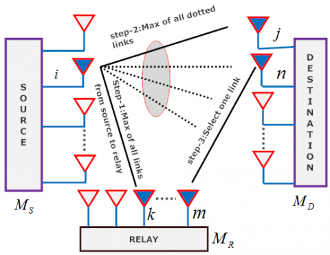
In Figure 2, it has given the various steps involve in the broadcast phase and in the other phase of selecting the antennas in strategy I. Broadcast phase is comprised of two steps. Broadcast phase involves the selection of i^{th}, j^{th} and k^{th} aerials respectively, shown in Figure 2.
Figure 1. Selection strategy I
Figure 2. Selection strategy II
In step 1, i^{th} antenna at the source and k^{th} antenna at the relay is selected depending on the maximum instantaneous gain \mathbb{Q}_{SR} of all fading links. In step 2, j^{th} antenna at the destination node has been selected depending on the maximum instantaneous gain \mathbb{Q}_{SD} of the fading channels displayed as dotted lines. Lastly, in step 3, one antenna is selecting between m^{th} antenna at the relay node and n^{th} antenna at the destination node. \mathbb{Q}_{SR}, \mathbb{Q}_{SD} and \mathbb{Q}_{RD} are given as,
\mathbb{Q}_{S R}=\max \left(\mathbb{Q}_{S_{1}, R_{1}}, \mathbb{Q}_{S_{2}, R_{2}}, \cdots \ldots, \mathbb{Q}_{S_{M_{S}}, R_{M}}\right), 1 \leq i \leq M_{S}, 1 \leq k \leq M_{R}
\mathbb{Q}_{S D}=\max \left(\mathbb{Q}_{S_{1}, D_{1}}, \mathbb{Q}_{S_{i}, D_{2}}, \cdots \ldots, \mathbb{Q}_{S_{i}, D_{M_D}}\right), 1 \leq i \leq M_{D}, \mathbb{Q}{RD}=\mathbb{Q}_{Ri,Di'}, 1 \leq m \leq M_{R}, 1 \leq n \leq M_{D} (8)
The cumulative distribution function (CDF) and probability distribution function (PDF) of the \mathbb{Q}_{SD}, \mathbb{Q}_{SR} and \mathbb{Q}_{RD} is modeled as [8],
F_{\mathbb{Q}_{S D}}(\mathbb{Q})=\left(1-\exp \left(\frac{-\mathbb{Q}}{\delta_{S D}^{2}}\right)\right)^{M_{D}}
f_{\mathbb{Q}_{S D}}(\mathbb{Q})=\frac{M_{D}}{\delta_{S D}^{2}} \exp \left(\frac{-\mathbb{Q}}{\delta_{S D}^{2}}\right)\left(1-\exp \left(\frac{-\mathbb{Q}}{\delta_{S D}^{2}}\right)\right)^{M_{D}-1}
F_{Q_{S R}}(\mathbb{Q})=\left(1-\exp \left(\frac{-\mathbb{Q}}{\delta_{S R}^{2}}\right)\right)^{M_{S} M_{R}}
F_{\mathbb{Q}_{R D}}(\mathbb{Q})=\left(1-\exp \left(\frac{-\mathbb{Q}}{\delta_{R D}^{2}}\right)\right)
f_{\mathbb{Q}_{R D}}(\mathbb{Q})=\frac{1}{\delta_{R D}^{2}} \exp \left(\frac{-\mathbb{Q}}{\delta_{R D}^{2}}\right) (9)
In study (Shankar et al., 2017), the end-to-end error Probability is given as,
P_{E}^{I}=P_{S \rightarrow D, R \rightarrow D} \times\left(1-P_{S \rightarrow R}\right)+P_{S \rightarrow D} \times P_{S \rightarrow R} (10)
Let ψ(λ_{SD}) represents the instantaneous symbol error rate of M-PSK modulation, given as (Varshney et al., 2015),
\psi\left(\lambda_{S D}\right)=\frac{1}{\pi} \int_{0}^{\left(\frac{M-1}{M}\right) \pi} \exp \left(\frac{-b}{\sin ^{2} \theta} \lambda_{S D}\right) d \theta (11)
Where b=\sin ^{2}(\pi / M), θ(α) denotes the Gaussian Q function, defined as (Varshney et al., 2008), \theta(\alpha)=\frac{1}{\pi} \int_{0}^{\frac{\pi}{2}} \exp \left(\frac{x^{2}}{\sin ^{2} \theta}\right) d \theta and b=\sin ^{2}\left(\frac{\pi}{M}\right).
The SER for SD link can be derived as (Varshney et al., 2017),
P_{S \rightarrow D}=E_{\mathbb{Q}_{S D}}\left\{\psi\left(\lambda_{S D}\right)\right\}=\int_{0}^{\infty} \psi\left(\mathbb{Q}_{S D}\right) f_{\mathbb{Q}_{S D}}(\mathbb{Q}) d \mathbb{Q}
=\frac{M_{D}}{\Pi \delta_{S D}^{2}} \int_{0}^{\infty} \int_{0}^{\frac{(M-1) \Pi}{M}} \exp \left(-\left(\frac{b P_{S}}{N_{0} \sin ^{2} \theta}+\frac{1}{\delta_{S D}^{2}}\right) \mathbb{Q}\right)\left(1-\exp \left(\frac{\mathbb{Q}}{\delta_{S D}^{2}}\right)\right)^{M_{D}-1} d \theta d \mathbb{Q} (12)
By using the expression, (1-x)^{M}=\sum_{m=0}^{M_{R}-1}\left(\begin{array}{c}{M} \\ {m}\end{array}\right)(-1)^{m} x^{m}, we further simplify P_{S \rightarrow D} as,
P_{S \rightarrow D}=M_{D} \sum_{j=0}^{M_{D}-1}\left(\begin{array}{c}{M_{D}-1} \\ {j}\end{array}\right)(-1)^{j} F\left(\frac{b P_{S} \delta_{S D}^{2}}{N_{0} \sin ^{2} \theta}+j+1\right) (13)
Following the similar procedure, SER for the SER link can be derived as,
P_{S \rightarrow R}=E_{\beta_{S R}}\left\{\psi\left(\lambda_{S R}\right)\right\}
=M_{S} M_{R} \sum_{i=0}^{M_{S} M_{R}-1}\left(\begin{array}{c}{M_{S} M_{R}-1} \\ {i}\end{array}\right)(-1)^{i} F\left(\frac{b P_{S} \delta_{S R}^{2}}{N_{0} \sin ^{2} \theta}+i+1\right) (14)
The SER for the cooperation mode can be written as,
P_{S \rightarrow D, R \rightarrow D}=E_{f_{\mathbb{Q}_{S D}} f_{\mathbb{Q}_{R D}}}\{\psi(\lambda)\}
=\frac{1}{\Pi} \int_{0}^{\frac{(M-1) \Pi}{M}} \int_{0}^{\infty} \psi\left(\mathbb{Q}_{S D}\right) f_{\mathbb{Q}_{S D}}\left(\mathbb{Q}_{S D}\right) d Q_{S D} \int_{0}^{\infty} \psi\left(\lambda_{R D}\right) f_{\beta_{R D}}\left(\mathbb{Q}_{R D}\right) d \mathbb{Q}_{R D}
=M_{D} \sum_{j=0}^{M_{D}-1}\left(\begin{array}{c}{M_{D}-1} \\ {j}\end{array}\right)(-1)^{j} F\left(\left(\frac{b P_{S} \delta_{S D}^{2}}{N_{0} \sin ^{2} \theta}+j+1\right)\left(\frac{b P_{R} \delta_{R D}^{2}}{N_{0} \sin ^{2} \theta}+1\right)\right) (15)
Substituting (13), (14) and (15) into (10), end to end SER for selection strategy I is expressed in (16).
P_{E}^{I}=M_{D} \sum_{j=0}^{M_{D}-1}\left(\begin{array}{c}{M_{D}-1} \\ {j}\end{array}\right)(-1)^{j} F\left(\frac{b P_{S} \delta_{S D}^{2}}{N_{0} \sin ^{2} \theta}+j+1\right)
\times M_{S} M_{R} \sum_{i=0}^{M_{S} M_{R}-1}\left(\begin{array}{l}{M_{S} M_{R}-1} \\ {i}\end{array}\right)(-1)^{i} F\left(\frac{b P_{S} \delta_{S R}^{2}}{N_{0} \sin ^{2} \theta}+i+1\right)
+M_{D} \sum_{j=0}^{M_{D}-1}\left(\begin{array}{l}{M_{D}-1} \\ {j}\end{array}\right)(-1)^{j} F\left(\left(\frac{b P_{S} \delta_{S D}^{2}}{N_{0} \sin ^{2} \theta}+j+1\right)\left(\frac{b P_{R} \delta_{R D}^{2}}{N_{0} \sin ^{2} \theta}+1\right)\right)
\times\left(1-M_{S} M_{R} \sum_{n=0}^{M_{S} M_{R}-1}\left(\begin{array}{c}{M_{S} M_{R}-1} \\ {n}\end{array}\right)(-1)^{n} F\left(\frac{b P_{S} \delta_{S R}^{2}}{N_{0} \sin ^{2} \theta}+n+1\right)\right) (16)
3.1.1. SER upper bound
For deriving the SER upper bound, we assume 1-P_{S \rightarrow R} \approx 1 at high SNR regimes. Tight SER upper bound of P_{E}^{I} can be given in (17),
P_{E}^{I}=\frac{M_{S} M_{R} M_{D}}{\pi^{2}} \int_{0}^{\left(\frac{M-1}{M}\right) \pi} \int_{0}^{\left(\frac{M-1}{M}\right) \pi}\left(\sum_{n=0}^{M_{S} M_{R}-1}\left(\begin{array}{c}{M_{S} M_{R}-1} \\ {n}\end{array}\right) \times \frac{(-1)^{n}}{\left(\frac{b P_{S} \delta_{S R}^{2}}{N_{0} \sin ^{2} \theta}+n+1\right) }\right)\times\left(\sum_{m=0}^{M_{D}-1}\left(\begin{array}{c}{M_{D}-1} \\ {m}\end{array}\right) \times \frac{(-1)^{m}}{\left(\frac{b P_{S} \delta_{S D}^{2}}{N_{0} \sin ^{2} \theta}+m+1\right)}\right)
\times d \theta_{1} d \theta_{2}+M_{D} \sum_{j=0}^{M_{D}-1}\left(\begin{array}{c}{M_{d}-1} \\ {j}\end{array}\right) \times(-1)^{j} \times\left[\frac{1}{\pi} \int_{0}^{\left(\frac{M-1}{M}\right) \pi} \frac{1}{\left(\frac{b P_{R}^{2} R_{R D}^{2}}{N_{0} \sin ^{2} \theta}+j+1\right)} \times \frac{1}{\left(\frac{b P_{R} \delta_{R D}^{2}}{N_{0} \sin ^{2} \theta}+1\right)} d \theta\right] (17)
Applying the approximation,
\sum_{n=0}^{N}\left(\begin{array}{c}{N} \\ {n}\end{array}\right)(-1)^{n} \frac{1}{x+n y}=\frac{N ! y^{N}}{\prod_{n=0}^{N}(x+n y)} (18)
We can write tight SER upper bound for the selection strategy I as,
P_{E}^{I} \leq \frac{M_{S} M_{R} M_{D}\left(M_{S} M_{R}-1\right) !\left(M_{D}-1\right) ! B_{0} B_{1}}{\pi^{2}\left(\frac{b P_{S} \delta_{S R}^{2}}{N_{0}}\right)^{N_{S} N_{R}}\left(\frac{b P_{S} \delta_{S D}^{2}}{N_{0}}\right)^{N_{D}}}+\frac{M_{D}\left(M_{D}-1\right) ! B_{1}}{\pi\left(\frac{b P_{S} \delta_{S D}^{2}}{N_{0}}\right)^{N_{D}}\left(\frac{b P_{R} \delta_{R D}^{2}}{N_{0}}\right)} (19)
Where B_{0}=\int_{0}^{\left(\frac{M-1}{M}\right) \pi}\left(\sin \theta_{1}\right)^{2 M_{S} M_{R}} d \theta_{1}, B_{1}=\int_{0}^{\left(\frac{M-1}{M}\right) \pi}\left(\sin \theta_{2}\right)^{2 M_{D}} d \theta_{2}.
3.1.2. Optimal power allocation
Substituting P_{R}=P_{0}-P_{S} in (19) and differentiating the resultant expression w.r.t. P_{S} and after equating it to zero, we can get,
K_{1}\left(M_{S} M_{R}+M_{D}\right) P_{S}^{-\left(M_{S} M_{R}+M_{D}+1\right)}
+K_{2}\left(P-P_{S}\right)^{-1} M_{D} P_{0}^{-\left(M_{D}+1\right)}-K_{2} P_{S}^{-\left(M_{D}\right)}\left(P-P_{S}\right)^{-2}=0 (20)
Where K_1 and K_2 are appropriately defined constant terms, given below,
K_{1}=\frac{M_{S} M_{R} M_{D}\left(M_{S} M_{R}-1\right) !\left(M_{D}-1\right) ! B_{0} B_{1}}{\pi^{2}\left(\frac{b \delta_{S R}^{2}}{N_{0}}\right)^{M_{S} M_{R}}\left(\frac{b \delta_{S D}^{2}}{N_{0}}\right)^{N_{D}}}, K_{2}=\frac{M_{D}\left(M_{D}-1\right) ! B_{1}}{\pi\left(\frac{b \delta_{S D}^{2}}{N_{0}}\right)^{N_{D}}\left(\frac{b \delta_{R D}^{2}}{N_{0}}\right)}.
Solution of (20) will give optimal powers for source and relay nodes.
3.1.3. DO calculation
Substituting \mathbb{Q}_{0}=\frac{P_{S}}{P}, \mathbb{Q}_{1}=\frac{P_{R}}{P}, (19) can be written as, (21),
P_{e} \leq \frac{M_{S} M_{R} M_{D}\left(M_{S} M_{R}-1\right) !\left(M_{D}-1\right) ! B_{0} B_{1}}{\pi^{2}\left(b \delta_{S R}^{2}\right)^{M_{S} M_{R}}\left(b \delta_{S D}^{2}\right)^{M_{D} \mathbb{Q}_{0}^{-\left(M_{S} M_{R}+M_{D}\right)}\left(P / N_{0}\right)^{-\left(M_{S} M_{R}+M_{D}\right)}}}
+\frac{M_{D}\left(M_{D}-1\right) ! B_{2}}{\pi \mathbb{Q}_{0}^{-}-M_{D}\left(b \delta_{S D}^{2}\right)^{M_D}\left(b \beta_{1} \delta_{R D}^{2}\right)\left(P / N_{0}\right)^{-\left(M_{D}+1\right)'}} (21)
DO expression is given as,
D O=-\quad \underbrace{\lim}_{S N R \rightarrow \infty {\frac{\log \left(P_{E}^{L}\right)}{\log (S N R)}}} \min _{S_{R}}
3.2. SER strategy II
In this selection strategy, the SD and SR link is having a similar error probability to the previous strategy. In this strategy between the relay and destination fading link we apply STBC. Let us define the PEP as the error probability when STBC codeword X_n is of confused with STBC codeword X_l. The PEP can be modeled as,
P\left(X_{n} \rightarrow X_{l} | H_{R D}\right)=Q(\sqrt{\frac{P_{R}}{2 M_{R} N_{0}} H_{R D}\left\|X_{n}-X_{l}\right\|_{F}^{2}})
Averaging the PEP over the probability distribution of the fading channel, the average pairwise error probability can be derived as,
P\left(X_{n} \rightarrow X_{l}\right)=G\left(\prod_{k=1}^{M_{R}}\left(1+\frac{P_{R} \lambda_{k, l} \sigma_{R D}^{2}}{4 N_{0} M_{R} \sin ^{2} \theta}\right)^{M_{D}}\right)=E_{H_{R D}}\left\{P\left(X_{n} \rightarrow X_{l} | H_{R D}\right)\right\}
Where \lambda_{1, l}, \lambda_{1, l}, \dots \dots \dots \dots \lambda_{M_{R}, l}, are the non-zero singular values of \left(X_{n}-X_{l}\right)\left(X_{n}-X_{l}\right)^{H} and G(x(\theta))=\int_{0}^{\frac{\pi}{2}} \frac{1}{x(\theta)} d \theta. For RD link the PEP can be upper bounded using union bound, which is very tight on high SNR,
P_{R \rightarrow D} \leq \sum_{X_{l} \in C, l \neq n}^{|C|} P_{R \rightarrow D}\left(X_{n} \rightarrow X_{l}\right)=
\sum_{X_{l} \in C, l \neq n}^{|C|} G\left(\prod_{k=1}^{M_{R}}\left(1+\frac{P_{R} \lambda_{k, l} \delta_{R D}^{2}}{4 N_{0} M_{R} \sin ^{2} \theta}\right)^{M_{D}}\right) (22)
P_{S \rightarrow D, R \rightarrow D}=E_{f_{\mathbb{Q} s d} f_{\mathbb{Q} r d}}\{\psi(\lambda)\}
=\frac{1}{\Pi} \int_{0}^{\frac{(M-1) \Pi}{M}} \int_{0}^{\infty} \psi\left(\lambda_{S D}\right) f_{\mathbb{Q}_{S D}}\left(\mathbb{Q}_{S D}\right) d \mathbb{Q}_{S D} \times \int_{0}^{\infty} \psi\left(\lambda_{R D}\right) f_{\mathbb{Q}_{R D}}\left(\mathbb{Q}_{R D}\right) d \mathbb{Q}_{R D} d \theta
\simeq \frac{1}{\Pi} \int_{0}^{\frac{(M-1)[1}{M} \int_{0}^{(M-1)]} \int_{0}^{\infty} \psi\left(\lambda_{S D}\right) f_{\mathbb{Q}_{S D}}\left(\mathbb{Q}_{S D}\right) d \mathbb{Q}_{S D} \times}\quad \int_{0}^{\infty} \psi\left(\lambda_{R D}\right) f_{\mathbb{Q}_{R D}}\left(\mathbb{Q}_{R D}\right) d \mathbb{Q}_{R D} d \theta_{1} d \theta_{2}
=M_{D} \sum_{m=0}^{M_{D}-1}\left(\begin{array}{c}{M_{D}-1} \\ {m}\end{array}\right)(-1)^{m} F\left(\frac{b P_{S} \delta_{S D}^{2}}{N_{0} \sin ^{2} \theta}+m+1\right) \times\sum_{X_{l} \in C, l \neq n}^{|C|} G\left(\prod_{k=1}^{M_{R}}\left(1+\frac{P_{R} \lambda_{k, l} \sigma_{R D}^{2}}{4 N_{0} M_{R} \sin ^{2} \theta}\right)^{M_{D}}\right) (23)
The end-to-end error probability for selection strategy II is given as,
P_{E}^{I I}=P_{S \rightarrow D} \times P_{S \rightarrow R}+P_{S \rightarrow D, R \rightarrow D} \times\left(1-P_{S \rightarrow R}\right) (24)
Substituting (13), (14) and (23) into (24), we are getting (25),
\begin{aligned} P_{E}^{I I} &=M_{D} \sum_{j=0}^{M_{D}-1}\left(\begin{array}{c}{M_{D}-1} \\ {j}\end{array}\right)(-1)^{j} F\left(\frac{b P_{S} \delta_{S D}^{2}}{N_{0} \sin ^{2} \theta}+j+1\right) \\ \times & M_{S} M_{R} \sum_{i=0}^{M_{S} M_{R}-1}\left(\begin{array}{c}{M_{S} M_{R}-1} \\ {i}\end{array}\right)(-1)^{i} F\left(\frac{b P_{S} \delta_{S R}^{2}}{N_{0} \sin ^{2} \theta}+i+1\right) \\+& M_{D} \sum_{m=0}^{M_{D}-1}\left(\begin{array}{c}{M_{D}-1} \\ {m}\end{array}\right)(-1)^{m} F\left(\frac{b P_{S} \delta_{S D}^{2}}{N_{0} \sin ^{2} \theta}+m+1\right) \\ & \times \sum_{X_{l} \in C, l \neq n}^{|C|} G\left(\prod_{k=1}^{M_{R}}\left(1+\frac{P_{R} \lambda_{k, l} \sigma_{R D}^{2}}{4 N_{0} M_{R} \sin ^{2} \theta}\right)^{M_{D}}\right) \end{aligned} (25)
Table 1. Optimal power allocation for SR link for selection strategy I
|
Number of Antennas |
\mathbb{Q}_0 |
\mathbb{Q}_1 |
|
M_{S}=1, M_{R}=1, M_{D}=1 |
0.60 |
0.40 |
|
M_{S}=2, M_{R}=2, M_{D}=2 |
0.70 |
0.30 |
|
M_{S}=2, M_{R}=3, M_{D}=3 |
0.73 |
0.27 |
Table 2. Optimal power allocation for SR link for selection strategy II
|
Number of Antennas |
\mathbb{Q}_0 |
\mathbb{Q}_1 |
|
M_{S}=1, M_{R}=1, M_{D}=1 |
0.60 |
0.40 |
|
M_{S}=2, M_{R}=2, M_{D}=2 |
0.53 |
0.47 |
|
M_{S}=3, M_{R}=3, M_{D}=3 |
0.48 |
0.52 |
Finally, the SER upper bound for strategy II can be written as,
P_{E}^{I I} \leq \frac{M_{S} M_{D} M_{R}\left(M_{S} M_{R}-1\right) !\left(M_{D}-1\right) ! B_{0} B_{1}}{\pi^{2}\left(\frac{b P_{S} \delta_{S R}^{2}}{N_{0}}\right)^{M_{S}}\left(\frac{b P_{S} \delta_{S D}^{2}}{N_{0}}\right)^{M_{D}}}+\frac{M_{D}\left(M_{D}-1\right) ! I_{2}^{2}}{\pi^{2}\left(\frac{b P_{S} \sigma_{S D}^{2}}{N_{0}}\right)^{M_{D}}\left(\frac{P_{R} \sigma_{R D}^{2}}{4 N_{0} M_{R}}\right)^{M_{D'}}} (28)
Where, Z=\sum_{X_{l} \in C, l \neq n}^{|C|} \lambda_{l}, \lambda_{l}=\prod_{k=1}^{M_{R}} \lambda_{k, l}, I_{2}=\frac{1}{\pi} \int_{0}^{\frac{(M-1) \pi}{2}}(\sin \theta)^{2 M_{D}} d \theta.
3.2.2. DO analysis
Substituting P_{S}=Q_{0} P, P_{R}=\mathbb{Q}_{1} P, we can express SER upper bound as,
P_{E}^{I I} \leq \frac{M_{S} M_{D} M_{R}\left(M_{S} M_{R}-1\right) !\left(M_{D}-1\right) ! B_{0} B_{1}}{\pi^{2}\left(b \mathbb{Q}_{0} \delta_{S R}^{2}\right)^{M_{S} M_{R}}\left(b \mathbb{Q}_{0} \delta_{S D}^{2}\right)^{M_{D}}\left(\frac{P}{N_{0}}\right)^{M_{S}M_R+M_D}}+\frac{M_{D}\left(M_{D}-1\right) ! I_{2} I_{4}}{\pi^{2}\left(b \mathbb{Q}_{0} \sigma_{S D}^{2}\right)^{M_{D}}\left(\frac{\mathbb{Q}_{1} \sigma_{R D}^{2} z}{4 M_{R}}\right)^{M_{D}}\left(\frac{P}{N_{0}}\right)^{2 N_{D}}} (29)
DO expression is given as,
DO=-\underset{SNR\to \infty }{\mathop Lim}\,\frac{\log (P_{E}^{I})}{\log (SNR)}=M_{D} \min \left(M_{S} M_{R}, M_{D}\right) (30)
3.2.3. Optimal power allocation
Substituting P_{R}=P_{S}-P in (28) and differentiating it with respect to P_{S}, after equating it to zero, the resultant expression we get,
K_{1} \times\left(M_{S} M_{R}+M_{D}\right)\left(P_{S}\right)^{-M_{S} M_{R}-M_{D}-1}+
K_{2}\left[\begin{array}{l}{M_{D}\left(P_{S}\right)^{M_{D}} \times\left(P-P_{S}\right)^{-\left(M_{D}+1\right)}} \\ {-M_{D}\left(P_{S}\right)^{-\left(M_{D}+1\right)}\left(P-P_{S}\right)^{M_{D}}}\end{array}\right]=0 (31)
Where K_1 and K_2 are appropriately defined constant terms. Solution of equation (31) will provide the optimal power for source and relay nodes.
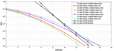
We analyzed the SER performance of the single relay relaying network for the identical and best possible power factors \mathbb{Q}_{0} and \mathbb{Q}_{1}. In Figure 3, the plots show that analytical results are in close agreement with simulated results. Also, SER simulated matches the SER upper bounds at high SNR regimes. It can be seen from the given graph that S2 performance is better than that of S1 and SER for optimal power outperforms SER for equal power allocation.
Figure 3. SER Simulated, SER Analytic, SER Upper bound for single relay relaying network with M=4, N_{0}=1, M_{S}=M_{R}=M_{D}=2, \delta_{S D}^{2}=\delta_{S R}^{2}=\delta_{R D}^{2}=2, \mathbb{Q}_{0}=0.70, \mathbb{Q}_{1}=0.30 for selection strategy S1 and \mathbb{Q}_{0}=0.53, \mathbb{Q}_{1}=0.47 for selection strategy S2
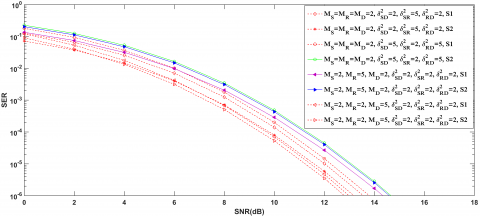
Figure 4. Comparison between selection strategy S1 and selection strategy S2 for various antenna configurations and various values of channel variables
In Figure 4, we show a comparison between selection strategy S1 and S2 in different channel conditions and different antenna configurations with M=4, N_{0}=1. Figure 4, shows that when M_{S}=2, M_{R}=5, M_{D}=2, \delta_{S D}^{2}=\delta_{S R}^{2} \operatorname{and} \delta_{R D}^{2}=2, SER performance of strategy S2(DO=10) is better than strategy S1 (DO=8); and when M_{S}=2, M_{R}=2, M_{D}=5, \delta_{S D}^{2}=\delta_{S R}^{2} \operatorname{and} \delta_{R D}^{2}=2, SER performance of strategy S1(DO=10) are better than strategy S2 (DO=8). Lastly, when M_{S}=2, M_{R}=2, M_{D}=2, \delta_{S D}^{2}=2, \delta_{S R}^{2}=5, \delta_{R D}^{2}=2 i.e., strategy S1 and S2 have same DO, SER performance of S1 is better than S2 by 3dB because it is based on the maximization of the SNR of source-to-destination fading link which is strong in this scenario; when M_{S}=2, M_{R}=2, M_{D}=2, \delta_{S D}^{2}=5, \delta_{S R}^{2}=2, \delta_{R D}^{2}=5, the strategy S2 performs better (1dB gain) because it is based on maximization of SNR of the relay to the destination and source-to-relay fading link which are strong in this scenario.
We investigated the SER performance of two antenna selection strategy S1 and S2 for S-DF relaying network over time invariant Rayleigh fading links. We presented the closed form expression for SER analytic and SER upper bound for both antenna selection strategies. Analytical outcomes have been validated with simulated outcomes. We have conducted simulations for various antenna configurations and various channel gains. We can select the antenna selection strategy which has maximum DO for that particular antenna configuration. In case both the strategies give the same DO then one can choose strategy I, when source-to-destination link is strong and strategy II, when source-to-destination link is weak as compared to source-to-relay and relay-to-destination fading links.
Amarasuriya G., Tellambura C., Ardakani M. (2011). Performance analysis framework for transmit antenna selection strategies of cooperative MIMO AF relay networks. IEEE Transactions on Vehicular Technology, Vol. 60, No. 7, pp. 3030-3044. https://doi.org/10.1109/TVT.2011.2157371
Halber A., Chakravarty D. (2018). Wireless relay placement optimization in underground room and pillar mines. Mathematical Modelling of Engineering Problems, Vol. 5, No. 2, pp. 67-75. https://doi.org/10.18280/mmep.050203
Ibrahim A. S., Sadek A. K., Su W., Liu K. J. R. (2008). Cooperative communications with relay-selection: When to cooperate and whom to cooperate with? IEEE Transactions on Wireless Communications, Vol. 7, No. 7, pp. 2814-2827. https://doi.org/10.1109/TWC.2008.070176
Jin X., No J., Shin D. (2013). Source transmit antenna selection for MIMO decode-and-forward relay networks. IEEE Transactions on Signal Processing, Vol. 61, No. 7, pp. 1657-1662. https://doi.org/10.1109/TSP.2013.2241053
Khattabi Y., Matalgah M. M. (2015). Conventional AF cooperative protocol under nodes-mobility and imperfect-CSI impacts: Outage probability and Shannon capacity. 2015 IEEE Wireless Communications and Networking Conference (WCNC), pp. 13-18. https://doi.org/10.1109/WCNC.2015.7127437
Krishna V. S., Bhatnagar M. R. (2014). Performance analysis of sub-optimal transmit and receive antenna selection strategies in single relay based DF cooperative MIMO networks. 2014 Twentieth National Conference on Communications (NCC), pp. 1-6. https://doi.org/10.1109/NCC.2014.6811367
Krishna V. S., Bhatnagar M. R. (2016). A joint antenna and path selection technique in single-relay-based DF cooperative MIMO networks. IEEE Transactions on Vehicular Technology, Vol. 65, No. 3, pp. 1340-1353. https://doi.org/10.1109/TVT.2015.2414511
Ryu G., Jang D., Jeong U., Ko K. (2018). BER performance analysis of orthogonal space-time block codes in cooperative MIMO DF relaying networks. 2018 IEEE International Conference on Communications (ICC), pp. 1-6. https://doi.org/10.1109/ICC.2018.8423038
Shankar R., Kumar I., Kumari A., Pandey K. N., Mishra R. K. (2017). Pairwise error probability analysis and optimal power allocation for selective decode-forward protocol over Nakagami-m fading channels. 2017 International Conference on Algorithms, Methodology, Models and Applications in Emerging Technologies (ICAMMAET), pp. 1-6. https://doi.org/10.1109/ICAMMAET.2017.8186700
Shankar R., Pandey K. N., Kumari A., Sachan V., Mishra R. K. (2017). C(0) protocol based cooperative wireless communication over Nakagami-m fading channels: PEP and SER analysis at optimal power. 2017 IEEE 7th Annual Computing and Communication Workshop and Conference (CCWC), pp. 1-7. https://doi.org/10.1109/CCWC.2017.7868399
Varshney N., Krishna A. V., Jagannatham A. K. (2015). Selective DF protocol for MIMO STBC based single/multiple relay cooperative communication: End-to-end performance and optimal power allocation. IEEE Transactions on Communications, Vol. 63, No. 7, pp. 2458-2474. https://doi.org/10.1109/TCOMM.2015.2436912
Varshney N., Puri P. (2017). Performance analysis of decode-and-forward-based mixed MIMO-RF/FSO cooperative systems with source mobility and imperfect CSI. Journal of Lightwave Technology, Vol. 35, No. 11, pp. 2070-2077. https://doi.org/10.1109/JLT.2017.2675447
Yang K., Cui H., Song L., Li Y. (2014). Joint relay and antenna selection for full-duplex AF relay networks. 2014 IEEE International Conference on Communications (ICC), pp. 4454-4459. https://doi.org/10.1109/ICC.2014.6884022