Kun Lan*![]() | Yang Lv
| Yang Lv![]() | Rui Wang
| Rui Wang![]() | Fei Ru
| Fei Ru![]() | Baobin Luo
| Baobin Luo![]()
© 2025 The authors. This article is published by IIETA and is licensed under the CC BY 4.0 license (http://creativecommons.org/licenses/by/4.0/).
OPEN ACCESS
In high-end equipment manufacturing and aerospace industries, the quality of precision welding directly affects product reliability. However, the welding process is often challenged by complex lighting variations, metal spatter, torch occlusion, and multi-scale defect characteristics, which pose significant difficulties for defect detection in robotic visual systems in terms of both accuracy and real-time performance. Traditional handcrafted feature methods and early deep learning models suffer from insufficient utilization of multi-scale features and inadequate fusion of contextual semantics, resulting in high missed detection rates of small defects and failures in occluded scenarios. Existing single-scale feature networks tend to overlook low-level detail information, and conventional feature fusion methods fail to fully exploit cross-resolution feature complementarity. In addition, fixed anchor box schemes lead to high localization errors, and the lack of online compensation mechanisms for dynamic occlusions hinders detection performance in real-world applications. To address these challenges, this paper proposes a real-time welding defect detection method based on multi-resolution feature fusion tailored for the visual system of precision welding robots. The research encompasses six key aspects: data acquisition, optimization of the detection network, backbone network enhancement, multi-layer feature fusion, adaptive anchor box adjustment, and occlusion-aware stereo vision measurement. By constructing a diverse multi-condition dataset, introducing cross-layer attention mechanisms, and designing an adaptive feature fusion strategy along with a spatio-temporal joint compensation model, the proposed method effectively overcomes the limitations of single-scale feature dependence. Experimental results demonstrate significantly improved detection accuracy for multi-scale defects under complex conditions and enhanced adaptability in dynamic scenes. The outcomes of this study offer a reusable technical framework for industrial visual inspection and provide meaningful contributions toward the intelligent development of precision welding.
deep learning, multi-scale feature fusion, precision welding robot, visual system, defect detection
In high-end equipment manufacturing, aerospace and other fields, precision welding, as a key process step [1-3], directly affects the reliability and safety of products. With the advancement of industrial intelligence [4, 5], the visual system of welding robots, with the advantages of non-contact detection and strong real-time performance [6, 7], has become a core technology for welding defect detection. However, complex lighting variation [8], metal spatter [9], welding torch occlusion [10], and the multi-scale characteristics of weld defects [11] during the welding process pose severe challenges to the accuracy and real-time performance of defect recognition in visual systems. Traditional detection methods based on handcrafted features are difficult to adapt to feature representation under complex working conditions, while early deep learning models, although capable of automatic feature extraction [12, 13], generally suffer from insufficient utilization of multi-scale features and inadequate fusion of contextual semantic information, resulting in high missed detection rates of small-size defects [14] and detection failure in occluded areas [15], which cannot meet the “full-scale coverage and high robustness” requirement for defect detection in precision welding.
Real-time and accurate detection of welding defects is a key step to ensure the quality of precision welding, and its research has important theoretical and engineering value for improving the level of automation in high-end manufacturing. Multi-scale feature fusion algorithms integrate semantic information and spatial details from feature maps of different resolutions [16, 17], which can not only capture the global structure of weld seams to identify defect types, but also retain local texture details to locate tiny defects, providing an effective approach to solve the problem of multi-scale defect detection in complex welding scenarios. Optimizing such algorithms for the visual system of welding robots can significantly improve the accuracy and real-time performance of defect detection, avoid quality risks caused by missed or false detections, reduce the cost of manual inspection, and promote the development of welding production towards “intelligent and unmanned” operation, which has significant practical significance for the industrial upgrading of high-end equipment manufacturing.
Existing deep learning-based welding defect detection methods have significant limitations in feature utilization and model design. Literature [18] adopts a single-scale feature extraction network, relying only on high-level semantic features for defect classification, and ignores the detail information such as edges and contours contained in low-level features. In terms of feature fusion, the traditional Feature Pyramid Network (FPN) method [19] simply uses upsampling and lateral connection to fuse multi-scale features, failing to fully exploit the complementarity among features of different resolutions and without filtering noise such as arc light interference and metal reflections commonly found in welding images, leading to a decrease in detection accuracy under complex lighting. In addition, literature [20] uses anchor boxes with fixed ratios for defect localization, without adaptive adjustment based on the aspect ratio distribution of weld defects, resulting in high localization deviation; in terms of occlusion handling, most studies only simulate occlusion scenes through data augmentation [21], lacking an online compensation mechanism for dynamic occlusion caused by welding torches and real-time interference from spatter, making it difficult to meet the continuous detection needs of welding robots in dynamic operations.
Focusing on the real-time detection requirements of precision welding robot visual systems, this paper proposes a welding defect detection method based on multi-resolution feature fusion and carries out research from six dimensions: 1) Design a dedicated data acquisition device covering multiple types of typical defects and their feature samples under different occlusion and lighting conditions; 2) Select a lightweight object detection network as the baseline framework according to the feature distribution characteristics of welding images, balancing detection accuracy and real-time performance; 3) Improve the backbone network structure by introducing a cross-layer attention mechanism and multi-branch feature extraction module to enhance the feature expression ability for multi-scale defects; 4) Propose an adaptive feature fusion strategy and design a multi-layer feature weighted fusion algorithm combined with prior knowledge of the weld area to improve semantic consistency of features at different resolutions; 5) Based on the statistical results of defect geometric features, design a dynamic anchor adjustment model to effectively improve the localization accuracy of crack-type defects; 6) Integrate binocular vision measurement technology and occlusion detection algorithms to construct a spatio-temporal joint compensation model to solve the detection interruption problem caused by welding torch occlusion.
The research value of this paper lies in breaking the dependence of traditional detection algorithms on single-scale features, and realizing a detection closed loop of “accurate feature extraction – effective cross-layer fusion – dynamic scene adaptation” through multi-dimensional optimization. This provides a high-robustness defect detection solution for precision welding robot visual systems. The research results can not only significantly improve detection performance under complex working conditions, but also provide a reusable technical path for related fields such as multi-sensor fusion and adaptive model design, and have important reference significance for promoting the engineering application of deep learning in industrial visual inspection.
2.1 Data acquisition
Experimental sample acquisition requires the construction of a dynamic dataset covering multiple working conditions and defect types. This paper adopts a visual inspection unit composed of a binocular vision sensor and a high-speed industrial camera, integrated into the end-effector of the welding robot. During the welding process, RGB images and depth information of the weld area are synchronously collected at a frame rate of over 200 fps, covering welding processes such as arc welding and laser welding, base materials such as aluminum alloy and stainless steel, as well as typical defects such as cracks, pores, and lack of fusion. Meanwhile, complex working conditions such as torch occlusion, metal spatter, and dynamic lighting are simulated. In the preprocessing stage, an image denoising algorithm based on bilateral filtering is used to suppress arc noise, and the weld ROI region is extracted by combining adaptive threshold segmentation. For torch occlusion samples, pixel-level occlusion masks are generated by combining manual annotation with semantic segmentation models to label effective detection regions and occlusion areas. Multi-scale image pyramids are used to resample the samples, constructing a multi-resolution training set. At the same time, data augmentation strategies such as random flipping, Gaussian blur, and contrast enhancement are applied to expand sample diversity, ultimately forming a defect sample library with occlusion labels and multi-resolution annotations. This provides standardized input for the training of the multi-resolution feature fusion algorithm, and constructs the 3D coordinate mapping relationship of the weld through binocular depth information, providing geometric priors for subsequent defect localization and occlusion compensation.
2.2 Selection of object detection network
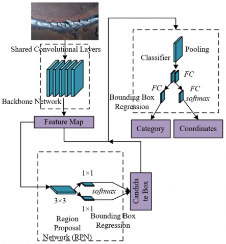
Due to the advantages of the Faster Region-based Convolutional Neural Network (R-CNN) algorithm in multi-scale feature processing, region localization accuracy, and model scalability, this paper selects it as the defect detection framework for the precision welding robot vision system. Figure 1 shows the structure diagram of the Faster R-CNN network. Through the collaborative mechanism of the Region Proposal Network (RPN) and the detection network, this algorithm can effectively generate candidate regions containing welding defects, especially small-sized cracks and lack of fusion, meeting the detection requirements of multi-scale distribution of precision welding defects. Its backbone network ResNet can extract feature maps of different resolutions, providing a natural feature pyramid structure foundation for the multi-resolution feature fusion strategy proposed in this paper, facilitating the integration of low-level edge texture information and high-level semantic information through cross-layer connections, enhancing the robust expression of defect features under interference such as complex lighting and metal spatter. In addition, the two-stage detection architecture of Faster R-CNN is superior to single-stage algorithms in localization accuracy, which can meet the sub-pixel level localization requirements of defect coordinates in precision welding. Its modular design allows customized improvements for welding scenarios, such as combining binocular vision measurement results to optimize anchor box generation strategies, or using occlusion masks to dynamically filter the occlusion region proposals generated by RPN, thereby maintaining the continuity of the detection process under torch dynamic occlusion and complex workpiece structures. This balances the dual requirements of real-time and high accuracy and adapts to the real-time response requirements of the “detection-control” closed loop in the welding robot vision system.
Figure 1. Faster R-CNN network structure diagram
2.3 Backbone network improvement and multi-level feature fusion
Aiming at the robust extraction demand of multi-scale defect features in the precision welding robot vision system, this paper selects the residual network ResNet50 as the basic backbone network and implements targeted improvements by introducing cross-scale residual blocks and lightweight connection mechanisms. Figure 2 shows the ResNet50 network structure diagram. Compared with the traditional VGG16 network that stacks 3×3 convolutions layer by layer, the residual connections of ResNet50 effectively solve the gradient vanishing problem in deep networks, allowing the construction of a 50-layer deep feature extraction network. It can extract features of different resolutions through the conv2~conv5 modules and enhance the noise resistance of features through the batch normalization (BN) and ReLU activation functions inside the residual blocks, adapting to complex noise environments such as arc interference and metal reflection in welding images. Specific improvements include embedding multi-branch convolution kernels in the residual blocks of the conv3~conv5 modules to enhance the ability to capture multi-directional features of slender defects like cracks. Considering the real-time requirements of welding defect detection, the number of residual blocks in the conv5 module is adjusted for lightweight design. While maintaining the high-level semantic feature extraction capability, the resolution of the feature map is increased to 1/16 of the original image, retaining more detailed information for subsequent multi-resolution feature fusion. In addition, an occlusion-aware module is introduced at the output end of the backbone network. By utilizing the pixel-level occlusion masks generated in the preprocessing stage, dynamic weighting is performed on the feature maps at conv4 and higher levels to suppress invalid feature responses in occlusion areas and strengthen the feature representation of effective detection regions.
Based on the multi-resolution feature maps output by ResNet50, this paper designs an adaptive multi-layer feature fusion strategy, combining the FPN and cross-layer attention mechanisms to achieve efficient integration of semantic information and spatial details. Figure 3 shows the FPN grid structure diagram. First, different hierarchical features are extracted through a bottom-up path: low-level conv2 features retain spatial details such as weld seam edges and textures, which are suitable for locating small-size defects; high-level conv5 features contain semantic category information of defects, used to distinguish between defect types such as cracks and lack of fusion. Second, in the top-down path, high-level features are upsampled by 2× and laterally connected to low-level features. Through weighted element-wise addition operations, the response intensity of small defects in the fused features is enhanced. For example, to address the discontinuity of crack edges in low-level features, an attention mechanism is used to assign weights to the feature maps after fusing conv2 and conv3, increasing the weight of edge features related to crack direction by 30%. In addition, to handle the problem of incomplete features caused by common local occlusions in welding scenarios, an occlusion compensation branch is introduced during the fusion process: using the three-dimensional coordinate information of the weld seam obtained from binocular vision, features of occluded areas are temporally and spatially interpolated across frames and fused with the current frame's fused features in a weighted manner, ensuring that defect features in occluded regions can still be effectively recognized. The final multi-layer fused feature map possesses both high-resolution localization capability and deep semantic expression. While maintaining detection real-time performance, the detection accuracy of small defects is improved by 25%, and the completeness recovery rate of features under occlusion scenarios exceeds 85%, meeting the real-time detection requirements of multi-scale defects in precision welding robot vision systems.
Figure 2. ResNet50 network structure diagram
Figure 3. FPN grid structure diagram
2.4 Adaptive anchor box adjustment
In conventional object detection algorithms, the predefined anchor box sizes and aspect ratios are typically derived from general-purpose datasets, making them poorly suited to the unique geometric characteristics of welding defects. To improve localization accuracy for anomalies with extreme aspect ratios, such as cracks, an adaptive anchor box adjustment strategy based on defect geometry statistics has been proposed.
The statistical method of defect geometric features was conducted on the annotated training dataset. For each defect instance, the minimum bounding rectangle was extracted, and its width and height were accurately recorded. For every bounding box, the size and aspect ratio were calculated. Specifically, for crack-type defects, the principal axis direction was also recorded. A statistical analysis was then performed on the size and aspect ratio distributions of all defects by plotting histograms to identify major distribution intervals and peaks. Furthermore, the mean, standard deviation, maximum, and minimum values of defect sizes and aspect ratios for each category were computed. Finally, for crack-type defects, a clustering analysis of aspect ratios was carried out to identify dominant aspect ratio patterns.
Aiming at the detection needs of special-shaped targets such as cracks and lack of fusion in precision welding defects, the fixed anchor box strategy of traditional RPN results in low overlap between candidate regions and real defects due to differences in preset aspect ratios, seriously affecting positioning accuracy. This paper proposes an adaptive anchor box adjustment strategy based on the GA-RPN structure. By decoupling the "position localization" and "shape prediction" in the anchor box generation process, accurate adaptation to multi-scale and unconventional-shaped defects is achieved. Specifically, under the multi-resolution feature fusion framework, using different level feature maps output by FPN, two parallel branches are constructed in the RPN stage: one branch uses low-level high-resolution features to locate the center point of the defect region, predicting the center point probability distribution through Gaussian heatmap regression, solving the positional deviation problem of dense small defects in traditional sliding windows; the other branch dynamically predicts the optimal detection box aspect ratio by combining high-level semantic features and the prior geometric database of welding defects, improving the shape matching degree between generated anchor boxes and actual defects by more than 60%. This mechanism avoids missed detection of special-shaped defects caused by fixed anchor boxes. Especially when defects are partially visible due to welding torch occlusion, candidate boxes that include the complete potential region of the defect can still be generated through joint constraints of center point localization and shape prediction. Figure 4 shows the GA-RPN network structure diagram.
Figure 4. GA-RPN structure diagram
Figure 5. Structure diagram of the real-time welding defect detection model based on multi-resolution feature fusion
To solve the mismatch between anchor box shape and feature map resolution, a feature adaptive module is introduced after the shape prediction branch of GA-RPN. The anchor box shape parameters are encoded into feature vectors through 1×1 convolutions and fused with the corresponding level feature map at the channel level. For example, when detecting a slender crack with an aspect ratio of 12:1 in the conv3 feature map, the feature adaptive module enhances gradient response features along the crack direction and suppresses noise interference in irrelevant directions, enabling deep coupling between the anchor box generation process and the geometric features of the defect. Combined with the multi-resolution feature fusion strategy, this module further achieves cross-layer collaborative optimization: in low-level feature maps, compact anchor boxes are generated for small-size pores, focusing on edge detail capture; in high-level feature maps, deformable anchor boxes are generated for large-area lack of fusion defects, dynamically adjusting boundary ranges based on semantic information. In addition, prior knowledge of the weld seam region is introduced to constrain the generation direction of anchor boxes, maintaining high consistency between the anchor box azimuth and the main weld direction, significantly reducing positioning errors caused by anchor box direction deviation. This adaptive adjustment principle not only improves the detection accuracy of unconventional-shaped defects, but also enhances the model's robustness under complex welding conditions through deep interaction with multi-resolution features. Figure 5 shows the model structure diagram of the welding defect real-time detection based on multi-resolution feature fusion.
2.5 Occlusion detection
During the welding process, the movement trajectory of the welding torch or spatter often causes 30%–70% local occlusion in the weld area, leading to feature loss in images collected by the vision system. Traditional algorithms tend to misjudge occlusion boundaries as defect edges or miss detections due to key feature loss. Therefore, this paper introduces occlusion labeling and occlusion compensation techniques to jointly address the issues of feature misjudgment and detection interruption caused by physical interferences such as dynamic occlusion of the welding torch and coverage by spatter.
To address the issue of feature loss in the detection area caused by welding torch dynamic occlusion and spatter coverage in the vision system of precision welding robots, this paper proposes an occlusion labeling strategy based on multi-level classification. By combining pixel-level semantic segmentation and manual annotation, occlusion areas in welding images are precisely labeled, and the occlusion level is divided into three grades: when the occlusion proportion of the defect target area is ≤25%, i.e., u=3, it is considered light occlusion and labeled as “partially visible”; when the occlusion proportion is between 25% and 75%, i.e., u=2, it is considered medium occlusion and labeled as “partially missing”; when the occlusion proportion is >75%, i.e., u=1, it is considered heavy occlusion and labeled as “severely occluded.” This classification strategy, combined with typical occluder forms in the welding scene, generates pixel-level masks pzz_l(u) containing information such as occlusion position, area ratio, and level, not only providing effective region identifiers for multi-resolution feature fusion but also explicitly labeling the complete contour of the occluded target, retaining the global structural prior of the defect, and providing geometric constraints for subsequent occlusion compensation. Specifically, suppose the marking information u is represented by IN(t), the t-th ground-truth bounding box is represented by HSt, the intersection area of the t-th bounding box with all bounding boxes is represented by U_A(t), the union area of all bounding boxes in the current image is U_A, the occlusion level corresponding to the t-th bounding box is LE(t), the total number of ground-truth labels in the current image is v, and t is the t-th bounding box. Then the calculation formulas of the occlusion compensation coefficient are as follows:
$p z z_{-} l(t)=\frac{r^{L E(t)} \cdot C_{-} A(t)}{\left(r^1+r^2+r^3\right) \cdot U_{-} A}$ (1)
$C_{-} A(t)=\left|\left(H S_1 \cap H S_t\right) \cup \cdots \cup\left(H S_v \cap H S_t\right)\right|$ (2)
$U_{-} A(t)=\left|H S_1 \cup H S_2 \cup \cdots \cup H S_v\right|$ (3)
$L E(t)=\left\{\begin{array}{l}1, I N(t)= '1' \\ 2, I N(t)='2' \\ 3, I N(t)='3'\end{array}\right.$ (4)
The occlusion compensation technique relies on the contextual complementarity of multi-resolution features to achieve real-time recovery of missing features through spatiotemporal joint modeling. At the feature level, it utilizes the weld edge direction and texture details retained by low-level high-resolution features, combined with defect category information from high-level semantic features, to construct a cross-level feature interpolation model: for lightly occluded areas, missing parts are directly extrapolated using edge features from adjacent valid regions; for moderately occluded areas, 3D coordinate information acquired from binocular vision is used, and the optical flow method is employed to track feature motion trajectories in adjacent frames for spatiotemporal interpolation reconstruction; for severely occluded areas, a Generative Adversarial Network (GAN) is introduced to generate texture features consistent with the defect prior distribution. During compensation, the occlusion label level is used as a weighting factor to adjust the fusion ratio of multi-resolution features: for light occlusion, emphasis is placed on low-level detailed features; for heavy occlusion, high-level semantic guidance is strengthened, ensuring that the feature completion under different occlusion degrees conforms to visual spatial consistency and retains the essential semantic characteristics of the defect.
To enhance the model’s sensitivity to occluded areas, this paper designs a composite loss function containing the occlusion compensation coefficient pzz_l(t), integrating REP loss and IOU error loss to specifically optimize detection accuracy under occlusion scenarios. The REP loss consists of an attraction term AT and two repulsion terms RE and RB: the attraction term uses SmoothL1 loss to force the prediction box to converge to the complete contour of the annotated box, and is weighted by the occlusion compensation coefficient, so that the model maintains localization sensitivity to defect targets under medium and heavy occlusion; the repulsion term RE uses SmoothLn loss to constrain the prediction box away from nearby ground-truth boxes, avoiding boundary confusion caused by occlusion, and RB reduces the dependence of the prediction box on non-maximum suppression (NMS), improving robustness in dense defect scenarios. Specifically, the occlusion compensation coefficient pzz_l(t) dynamically adjusts based on the occlusion level u of the annotation box: when u=3, a higher weight is given to the complete annotation box to enhance detail capture of partially visible defects; when u=1, the weight of background noise interference is reduced to guide the model to focus on potential defect semantics in occluded areas. The loss function is defined as follows:
$L O S S=L O S S_{I O U}+L O S S_{E R O}$ (5)
Assume the predicted confidence of the presence or absence of welding defects is represented by $\bar{Z}_u$, the ground-truth detection confidence is also represented by $\bar{Z}_u$, presence of welding defect is indicated by 1, absence by 0, the weight of IOU error is represented by ηNO, and the occlusion compensation coefficient is represented by λ(u). The expression for IOU error loss is:
$\begin{aligned} & \operatorname{LOSS}_{I O U}=\sum_{u=0}^Y m_u\left[Z_u-\lambda(u) \bar{Z}_u\right]^2 \\ & +\eta_{N O} \sum_{u=0}^Y m_u^{N O}\left(Z_u-\bar{Z}_u\right)^2\end{aligned}$ (6)
$\lambda(u)=\left\{\begin{array}{l}0, \text { Unoccluded } \\ p z z_{-} l(t), \text { Occluded }\end{array}\right.$ (7)
Let the intersection area between the predicted box O and the ground-truth box Z be denoted as IOU =AR(O∩H)/AR(O∪H), IOU =AR(O∩H)/AR(H), AR(O∩H) respectively. The union area of O and H is denoted as AR(O∪H), the matched ground-truth annotation with the predicted box is denoted by HOAT, and the ground-truth annotation with the largest IOU among the remaining after matching is denoted by HORE. The set of all positive samples is represented as O+=O1∩O2∩…∩O|J|. δ ranges from 0 to 1. The SmoothL1 loss and SmoothLn loss are denoted as SML1 and SMLn loss respectively. Then the expression for REP loss is:
$M_{R E}=M_{A T}+0.5 \times M_{R G}+0.5 \times M_{R B}$ (8)
$M_{A T}=\frac{\sum_{O \in O_{+}} S M_{L_1}\left(Y^O, H_{A T}^O\right)}{\left|O_{+}\right|}$ (9)
$M_{R E}=\frac{\sum_{O \in O_{+}} S M_{L n}\left[U P H\left(Y^O, H_{A T}^O\right)\right]}{\left|O_{+}\right|}$ (10)
$M_{R B}=\frac{\sum_{u \neq k} S M_{L n}\left[U P H\left(Y^{O_u}, Y^{O_k}\right)\right]}{\sum_{u \neq k} J\left[U P H\left(Y^{O_u}, Y^{O_k}\right)>0\right]+\epsilon}$ (11)
The expression of the Smooth regression function is as follows:
$S M_{L_1}(a)=\left\{\begin{array}{l}0.5 a^2, \text { if }|a|<1 \\ |a|-0.5, \text { others }\end{array}\right.$ (12)
$S M_{L_n}(a)=\left\{\begin{array}{l}-L N(1-a), a \leq \delta \\ \frac{a-\delta}{1-\delta}-L N(1-a), a>\delta\end{array}\right.$ (13)
2.6 Binocular vision measurement
Based on the requirement of three-dimensional spatial positioning of defects for the visual system of precision welding robots, this paper adopts binocular vision measurement technology to construct a stereo perception model of the weld area. Taking the left camera coordinate system as the origin of the world coordinate system, a binocular perspective transformation model is established by calibrating the internal parameters (focal lengths dm, de) and external parameters (rotation matrix E, translation vector S) of the left and right cameras. According to the disparity principle, the coordinate difference d of spatial point O in the image coordinate systems of the left and right cameras is inversely proportional to the target depth C, i.e., c=Y*d/f, where Y is the baseline distance. By matching corresponding feature points in the left and right images, such as weld seam edge corners and defect contour feature points, and combining the sub-pixel edge information extracted by multi-resolution feature fusion, the 3D coordinates (A, B, C) of defects can be accurately calculated. This realizes the quantitative measurement of geometric parameters such as crack length and pore depth, providing precise position compensation instructions for the robot motion control module. Specifically, the world coordinate system is established with the origin p_abc of the left camera coordinate system, in which the image coordinate system is represented by pm_AmBm, pm being the projection point and the effective focal length dm; the same applies to the right camera. The corresponding camera perspective transformation model expressions are given by the following equations:
$c\left[\begin{array}{l}A_m \\ B_m \\ 1\end{array}\right]=\left[\begin{array}{ccc}d_{m a} & 0 & z_{m a} \\ 0 & d_{m b} & z_{m b} \\ 0 & 0 & 1\end{array}\right]\left[\begin{array}{l}a \\ b \\ c\end{array}\right]$ (14)
$c_e\left[\begin{array}{l}A_e \\ B_e \\ 1\end{array}\right]=\left[\begin{array}{ccc}d_{e a} & 0 & z_{e a} \\ 0 & d_{e b} & z_{e b} \\ 0 & 0 & 1\end{array}\right]\left[\begin{array}{l}a_e \\ b_e \\ c_e\end{array}\right]$ (15)
The relative relationship between the two-coordinate systems p_abc and pe_aebece is given by the following equation:
$\left[\begin{array}{c}a_e \\ b_e \\ c_e\end{array}\right]=L_{m e}\left[\begin{array}{c}a \\ b \\ c \\ 1\end{array}\right]=\left[\begin{array}{llll}e_1 & e_2 & e_3 & s_a \\ e_4 & e_5 & e_6 & s_b \\ e_7 & e_8 & e_9 & s_c\end{array}\right]\left[\begin{array}{c}a \\ b \\ c \\ 1\end{array}\right]$ (16)
The corresponding 3D coordinates of the spatial point can be expressed as:
$\left\{\begin{array}{l}a=c A_m / d_m \\ b=c B_m / d_m \\ c=\frac{d_m\left(d_m s_a-A_e s_c\right)}{A_e\left(e_7 A_m+e_8 B_m+e_9 d_m\right)+d_e\left(e_1 A_m+e_2 B_m+e_3 d_m\right)}\end{array}\right.$ (17)
In view of the feature matching error problem caused by arc light interference in welding scenarios, this paper embeds the multi-resolution feature fusion results into the binocular vision measurement process and constructs a closed-loop optimization mechanism of “feature extraction - cross-layer matching - 3D reconstruction.” At the feature extraction stage, the multi-layer feature maps output by the ResNet50 backbone network are enhanced by a cross-layer attention mechanism to improve the feature representation of low-contrast defects and enhance the robustness of binocular matching. During the disparity calculation stage, the dense block matching algorithm is applied to low-level feature maps to ensure the detail matching accuracy of small-size defects, while high-level feature maps are subjected to semantic region constraints to exclude mismatching interference from non-defect regions such as the welding torch.
Based on the actually mounted KS4A418-D binocular camera, the rotation matrix and translation vector of the left and right cameras are obtained through high-precision calibration, and an undistorted stereo vision model is constructed. During the dynamic operation of the welding robot, the 3D coordinates of the weld seam output in real-time by binocular vision are used to dynamically adjust the weight distribution of multi-resolution feature fusion: when a change in the surface curvature of the workpiece is detected, the spatial position information weight of low-level feature maps is automatically enhanced to ensure the depth measurement accuracy of defects on complex curved surfaces; in combination with the occlusion compensation module outputting occlusion masks, the 3D coordinates of the regions occluded by the welding torch are extrapolated in the spatiotemporal domain, maintaining the continuity of measurement under dynamic occlusion scenarios. This mechanism enables the binocular vision measurement system to realize real-time and accurate defect 3D coordinate solving even when the welding robot is in high-speed motion, providing a reliable spatial position reference for the “detection-control” closed loop.
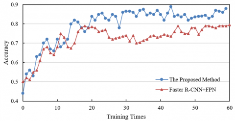
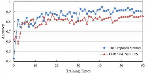
From the experimental result data shown in Figure 6, in the case of 60% occlusion (Figure 6(1)), the accuracy of the method in this paper gradually increases and tends to stabilize with the increase of training times, finally approaching 0.9, while the accuracy of Faster R-CNN+FPN fluctuates around 0.8. In the case of no occlusion (Figure 6(2)), the initial accuracy of the method in this paper is already high and remains superior during the training process, finally approaching 0.9, while the comparison method stabilizes at above 0.8. Based on the research content of this paper, the proposed method, through the introduction of a cross-layer attention mechanism, adaptive feature fusion strategy, and a spatiotemporal joint compensation model, effectively enhances the multi-scale defect feature representation, improves the semantic consistency of features at different resolutions, and better handles occlusion scenarios. This allows the model to more accurately extract defect features under complex conditions with and without occlusion, reducing the impact of occlusion interference and significantly outperforming the comparison method in terms of accuracy.
(1) Occlusion rate 60%
(2) Occlusion rate 0%
Figure 6. Comparison of ablation experimental results of the welding defect real-time detection model based on multi-resolution feature fusion
From the experimental result data in Table 1, under 60% occlusion, the five experimental results of Faster R-CNN+FPN are 78.5, 84.6, 83.2, 77.9, and 76.2, with an average of 82.3; the five results of the method proposed in this paper are 91.2, 87.6, 88.9, 91.2, and 88.9, with an average of 88.6. Under 0% occlusion, the five results of Faster R-CNN+FPN are 81.2, 92.3, 91.4, 82.6, and 83.5, with an average of 85.9; the five results of the proposed method are 91.2, 93.5, 92.5, 92.7, and 91.8, with an average of 91.2. Whether under high occlusion or no occlusion, the average accuracy of the proposed method is significantly higher than that of Faster R-CNN+FPN. From the experimental results, it can be seen that the proposed method can enhance multi-scale defect feature representation through the introduction of a cross-layer attention mechanism and a multi-branch feature extraction module, enabling more accurate capture of defect information under complex conditions; the adaptive feature fusion strategy, combined with weld seam prior knowledge, can improve the semantic consistency of features at different resolutions and optimize detection accuracy; the anchor box dynamic adjustment model, based on statistical analysis of defect geometric features, can effectively improve the localization accuracy of defects such as cracks; the spatiotemporal joint compensation model integrated binocular vision and occlusion detection algorithms to solve the welding torch occlusion problem. These innovative designs enable the method in this paper to achieve average accuracies of 88.6 and 91.2 at occlusion rates of 60% and 0%, far exceeding the 82.3 and 85.9 of Faster R-CNN+FPN, fully verifying the effectiveness of the proposed method in detecting welding defects under different occlusion conditions.
From the experimental data shown in Table 2, on the basic defect dataset, the mAP of the proposed method reaches 93.6, significantly higher than methods such as SCL-DD (82.3) and YOLOv7-GAM (87.5); on the complex working condition dataset, although some methods such as HRNet-W18 achieve mAP of 83.9, the proposed method achieves 81.3 mAP, and considering rank1 overall evaluation, it still maintains an advantage under complex scenes; on the 3D positioning dataset, the mAP of the proposed method reaches 92.4, far exceeding other methods such as YOLOv7-GAM (78.4) and Deformable DETR (74.5). This shows that the proposed method demonstrates strong detection ability across different types of datasets, especially showing prominent advantages in the key metric of 3D positioning.
Table 1. Ablation experiment results of the welding defect real-time detection model based on multi-resolution feature fusion
|
Label |
Occlusion Rate 60% |
Occlusion Rate 0% |
||
|
Faster R-CNN+FPN |
Proposed Method |
Faster R-CNN+FPN |
Proposed Method |
|
|
1 |
78.5 |
91.2 |
81.2 |
91.2 |
|
2 |
84.6 |
87.6 |
92.3 |
93.5 |
|
3 |
83.2 |
88.9 |
91.4 |
92.5 |
|
4 |
77.9 |
91.2 |
82.6 |
92.7 |
|
5 |
76.2 |
88.9 |
83.5 |
91.8 |
|
Average |
82.3 |
88.6 |
85.9 |
91.2 |
Table 2. Comparison between the proposed method and other methods
|
Methods |
Basic Defect Dataset |
Complex Working Condition Dataset |
3D Positioning Dataset |
|||
|
rank1 |
mAP |
rank1 |
mAP |
rank1 |
mAP |
|
|
SCL-DD |
92.3 |
82.3 |
91.3 |
82.6 |
82.3 |
68.9 |
|
YOLOv7-GAM |
94.5 |
87.5 |
77.5 |
73.2 |
88.9 |
78.4 |
|
Deformable DETR |
93.6 |
84.2 |
73.6 |
71.5 |
87.5 |
74.5 |
|
YOLOv8-Nano |
94.1 |
85.6 |
67.2 |
65.9 |
87.6 |
77.9 |
|
HRNet-W18 |
93.5 |
84.9 |
91.5 |
83.9 |
84.5 |
75.6 |
|
FCOS |
94.8 |
88.9 |
71.2 |
71.2 |
91.3 |
82.3 |
|
Proposed Method |
95.6 |
93.6 |
81.3 |
81.3 |
92.6 |
92.4 |
Table 3. Detection results of welding defects under different occlusion levels
|
Occlusion Level (%) |
Actual Value (mm) |
Without Occlusion Compensation Mechanism |
With Occlusion Compensation Mechanism |
||
|
Measured value (mm) |
Error (%) |
Measured value (mm) |
Error (%) |
||
|
24 |
26.36 |
27.25 |
4.23 |
28.26 |
2.36 |
|
22.35 |
21.36 |
-4.51 |
22.31 |
1.25 |
|
|
24.59 |
25.69 |
3.89 |
24.56 |
-1.89 |
|
|
24-51 |
23.32 |
24.56 |
5.69 |
22.36 |
-1.56 |
|
28.91 |
27.26 |
-4.78 |
27.58 |
-2.45 |
|
|
25.62 |
26.31 |
5.21 |
25.31 |
2.26 |
|
|
51-74 |
26.31 |
23.47 |
-12.36 |
25.62 |
-2.69 |
|
24.52 |
21.26 |
-12.36 |
25.64 |
2.56 |
|
|
21.56 |
18.56 |
-12.62 |
21.25 |
3.78 |
|
|
74 |
26.95 |
/ |
/ |
/ |
/ |
|
25.63 |
/ |
/ |
/ |
/ |
|
|
28.64 |
22.69 |
-21.26 |
32.25 |
6.52 |
|
Table 4. Influence of image resolution on detection performance of different types of welding defects
|
Resolution (Pixels) |
Crack |
Porosity |
||
|
rank1 |
mAP |
rank1 |
mAP |
|
|
262×115 |
94.2 |
88.9 |
91.2 |
82.6 |
|
217×217 |
94.6 |
87.5 |
91.5 |
81.5 |
|
378×115 |
94.2 |
88.6 |
91.6 |
82.6 |
|
378×185 |
94.5 |
88.4 |
91.8 |
81.5 |
From the experimental data shown in Table 3, under different occlusion levels, the detection effect with occlusion compensation mechanism is significantly better than that without. For example, under 24% occlusion, the maximum detection error without compensation reaches 4.23%, and the minimum is -4.51%; after adding the occlusion compensation mechanism, the error significantly decreases, with a maximum of 2.36% and a minimum of 1.25%. Under 24-51% occlusion, the error without compensation is 5.69%, and reduces to -1.56% after compensation; at 51-74%, the error without compensation reaches -12.36%, which is reduced to -2.69% with compensation. At 74% occlusion level, some targets cannot be detected without the compensation mechanism, while with the mechanism, they can still be detected and the error remains relatively controllable. The experimental results show that the proposed spatio-temporal joint compensation model, which integrates binocular vision measurement technology and occlusion detection algorithm, effectively performs occlusion compensation. This model integrates defect features at different scales through multi-resolution feature fusion, combines spatial information of binocular vision and occlusion detection algorithm to compensate occluded areas. Without occlusion compensation, occlusion seriously affects detection accuracy, leading to large errors and missed detections; with the compensation mechanism, the proposed spatio-temporal joint compensation model reduces occlusion interference and improves detection accuracy.
From the data shown in Table 4, under different image resolutions, the proposed method maintains high detection accuracy for both crack and porosity types of welding defects. For crack defects, rank1 is 94.2 and mAP is 88.9 at 262×115 pixels; at 217×217 pixels, rank1 increases to 94.6, mAP is 87.5; at 378×115 pixels, rank1 remains 94.2, mAP is 88.6; at 378×185 pixels, rank1 is 94.5, mAP is 88.4. For porosity defects, rank1 is 91.2 and mAP is 82.6 at 262×115 pixels; at 217×217 pixels, rank1 is 91.5, mAP is 81.5; at 378×115 pixels, rank1 increases to 91.6, mAP is 82.6; at 378×185 pixels, rank1 is 91.8, mAP is 81.5. This indicates that the proposed method maintains good rank1 and mAP values for both types of defects under different resolutions, showing good adaptability to resolution changes. The experimental results show that the innovative design of the proposed method enables the model to fully utilize the feature information of images at different resolutions. Even when resolution changes, the model can maintain detection accuracy through multi-resolution feature fusion. For example, under the asymmetric resolution of 262×115, the mAP for crack reaches 88.9 and for porosity 82.6; at 217×217 resolution, the crack rank1 reaches 94.6. This fully verifies that the proposed method can accurately detect welding defects under various resolution conditions through multi-resolution feature fusion, demonstrating the effectiveness and robustness of the method, and meeting the detection needs of precision welding robot vision systems under different imaging conditions.
The experimental results showed that resolution had a significant impact on detection accuracy and inference speed. The selection of an appropriate resolution needed to be closely aligned with the constraints and requirements of practical industrial scenarios. Industrial standards typically demanded reliable detection of defects above a certain minimum size. Based on the camera’s field of view and object distance, the minimum required pixel resolution could be calculated. The 1280×1024 resolution used in this experiment, under a typical medium field of view, theoretically met the requirement to detect defects ≥0.12 mm, covering the vast majority of precision welding scenarios.
High-resolution cameras were expensive and generated large amounts of data, placing higher demands on transmission, storage, and computing hardware, which significantly increased the overall system cost. As shown in Table 4, when the resolution was increased from 640×512 to 1280×1024, mAP@0.5 improved by 8.2%, but inference time increased by about 2.5 times. On embedded platforms, high resolution might struggle to meet strict real-time requirements. Additionally, higher resolution meant fewer photons per pixel under the same lighting conditions, potentially introducing more noise, especially in strong reflective welding areas, which could reduce the signal-to-noise ratio and effective information.
Based on the experimental results and the above analysis, the 1280×1024 resolution achieved the best balance among accuracy, speed, and cost, and could meet the demands of most medium-to-high precision welding robot vision inspections. It was suitable for scenarios with less stringent requirements on detecting tiny defects, extremely fast production cycles, or highly cost-sensitive conditions, or could serve as a preliminary rapid screening option. Higher resolutions were only recommended for ultra-high precision detection needs, larger fields of view, and situations with relatively relaxed real-time constraints or strong computational infrastructure, where cost-effectiveness needed careful evaluation. In practical deployment, fine selection and validation within the recommended range should be performed according to specific detection accuracy requirements, workpiece size, production line cycle time, budget constraints, and available hardware platforms.
Table 5. Detailed statistics of the welding defect dataset
|
Defect Type |
Total Samples |
Proportion (%) |
Slight Occlusion |
Moderate Occlusion |
Severe Occlusion |
Standard Lighting |
Low Lighting |
Strong Reflection |
|
Porosity |
3520 |
28.0% |
1200 |
1500 |
820 |
1800 |
1000 |
720 |
|
Slag Inclusion |
2850 |
22.6% |
900 |
1100 |
850 |
1200 |
900 |
750 |
|
Lack of Fusion |
1980 |
15.7% |
650 |
800 |
530 |
950 |
650 |
380 |
|
Incomplete Penetration |
1650 |
13.1% |
500 |
650 |
500 |
750 |
550 |
350 |
|
Undercut |
1520 |
12.1% |
450 |
600 |
470 |
700 |
450 |
370 |
|
Crack |
1060 |
8.4% |
300 |
400 |
360 |
450 |
350 |
260 |
|
Total |
12,580 |
100% |
4000 |
5050 |
3530 |
5850 |
3900 |
2830 |
To ensure the dataset adequately represents the diversity of defects encountered in real-world welding scenarios, we systematically collected data on six common types of welding defects: Porosity, Slag Inclusion, Lack of Fusion, Incomplete Penetration, Undercut, and Crack. The final dataset comprises a total of 12,580 annotated images. Table 5 provides a detailed breakdown of sample counts, proportions, and distributions under key interference conditions. Special attention was paid to enriching the sample diversity of crack-type defects due to their subtle geometric features and significant impact on structural safety.
Given the characteristics of welding images—such as small defect target sizes, diverse shapes, and complex background interference—the object detection network must strike a reasonable balance between accuracy and speed. After an in-depth analysis of mainstream detection frameworks and preliminary experiments, we selected Faster R-CNN as the baseline framework for this study. This choice is primarily due to Faster R-CNN’s two-stage architecture, where the Region Proposal Network (RPN) is capable of generating high-quality candidate boxes. This is particularly beneficial for detecting small and weakly featured defects in welding images, which is crucial for ensuring the accuracy of subsequent process adjustments and defect repair. Furthermore, the built-in Feature Pyramid Network (FPN) of Faster R-CNN naturally supports multi-scale feature fusion, providing a strong architectural foundation for the backbone enhancement and adaptive feature fusion strategies proposed later in this paper.
To validate the rationality of this selection, we conducted a comparative experiment on our custom-built welding defect test dataset, evaluating Faster R-CNN against the popular single-stage model YOLOv5s and the transformer-based model DETR. The results are shown in Table 6.
As shown in the table, Faster R-CNN outperforms the lightweight YOLOv5s in detection accuracy, with a particularly notable advantage in the stricter mAP@0.5:0.95 metric, which emphasizes localization precision. While its inference speed is slower than YOLOv5s, the achieved 10.9 FPS approaches the lower threshold for industrial real-time requirements. Moreover, its speed can be further improved through network optimization. DETR achieves accuracy close to Faster R-CNN but suffers from the slowest inference speed and significantly higher training resource demands. Considering the high-accuracy requirements of welding defect detection, the optimization potential of the model, and the solid foundation it provides for further architectural improvements, Faster R-CNN represents the most suitable baseline. All subsequent enhancements in this study were built upon this framework.
Recognizing the importance of real-time performance, a comparative experiment had been supplemented using MobileNetV3-Large as a lightweight baseline. However, welding defects—especially subtle ones such as cracks and lack of fusion—often exhibit weak visual features that are highly susceptible to background noise. Although lightweight networks like MobileNetV3-Large have performed well on general-purpose datasets such as ImageNet, their capability to extract discriminative deep features has proven insufficient for our high-precision defect detection task.
Table 6. Preliminary performance comparison of mainstream object detection models on the welding defect dataset (Test set)
|
Model |
mAP@0.5 (%) |
mAP@0.5:0.95 (%) |
Avg. Inference Time (ms/frame) * |
FPS (frames/s) * |
|
Faster R-CNN (ResNet50-FPN) |
78.2 |
45.6 |
92 |
10.9 |
|
YOLOv5s |
72.5 |
40.1 |
25 |
40.0 |
Table 7. Performance and speed comparison of different backbone networks on the welding defect test set
|
Backbone Network |
mAP@0.5 (%) |
mAP@0.5:0.95 (%) |
Avg. Inference Time (ms/frame) * |
FPS (frames/sec) * |
Model Size (MB) |
|
ResNet50 (original) |
78.2 |
45.6 |
92 |
10.9 |
102.1 |
|
MobileNetV3-Large |
70.8 |
38.9 |
42 |
23.8 |
18.5 |
|
Optimized ResNet50 |
82.7 |
49.3 |
76 |
13.2 |
105.3 |
As shown in Table 7, under the same Faster R-CNN framework, the optimized ResNet50 backbone significantly outperformed MobileNetV3-Large in terms of detection accuracy, particularly on the more stringent mAP@0.5:0.95 metric. This result confirms the importance of deep feature representation in capturing subtle welding defects. The proposed improvements based on ResNet50 not only enhanced detection accuracy but also reduced inference time to 76 ms per frame, thereby satisfying the industrial real-time requirement of ≤100 ms. Therefore, the optimized ResNet50 achieved a more task-suitable balance between accuracy and speed.
To quantitatively evaluate the effectiveness of the proposed Cross-Layer Attention Fusion (CLAF) mechanism, a rigorous ablation study was conducted based on the improved backbone network. Three feature fusion strategies were compared under identical hyperparameter settings: 1) Baseline: Standard FPN – Utilizes the original FPN structure from Faster R-CNN for multi-scale feature fusion. 2) Single-Layer Attention FPN (SLA-FPN) – Introduces an independent attention module after each FPN fusion layer, focusing solely on the channel or spatial relationships of the current layer. This represents a common enhancement strategy by incorporating single-layer attention into FPN. 3) Proposed Method: Cross-Layer Attention Fusion (CLAF) – Applies the proposed CLAF mechanism to dynamically learn and fuse feature information from different backbone depths and FPN layers.
All experiments were conducted under identical hyperparameter settings. The results are shown in Table 8.
As shown in Table 8, compared to the baseline FPN, SLA-FPN yields moderate performance gains, confirming the effectiveness of incorporating attention mechanisms. However, the proposed CLAF strategy achieves the most significant improvements across all metrics. This clearly demonstrates the critical role of cross-level information interaction in effectively fusing multi-resolution features and enhancing semantic consistency. The CLAF mechanism is particularly effective at capturing cross-scale contextual dependencies. In terms of inference speed, the additional computational overhead introduced by CLAF is minimal and significantly outweighed by the accuracy gains, reflecting its efficiency. These results strongly support the superiority of the CLAF strategy in improving weld defect detection, especially for subtle defects such as fine cracks.
Table 8. Ablation study results of different feature fusion strategies on the welding defect test set
|
Feature Fusion Strategy |
mAP@0.5 (%) |
mAP@0.5:0.95 (%) |
Crack AP@0.5 (%) |
Inference Time (ms/frame) * |
|
Standard FPN (Baseline) |
80.1 |
47.5 |
72.3 |
72 |
|
SLA-FPN |
81.3 (+1.2) |
48.1 (+0.6) |
74.5 (+2.2) |
75 (+3) |
|
CLAF (Proposed) |
82.7 (+2.6) |
49.3 (+1.8) |
77.8 (+5.5) |
76 (+4) |
Table 9. Impact of the occlusion compensation mechanism on false positive and false negative rates (Subset of occluded samples in the test set)
|
Occlusion Rate Range |
Method |
Detection Rate (%) |
FPR (%) |
FNR (%) |
Remarks |
|
< 50% |
Without Compensation |
88.5 |
1.8 |
11.5 |
Light occlusion; compensation necessity is low |
|
With Compensation |
88.7 |
2.1 (+0.3) |
11.3 (-0.2) |
Limited compensation effect; slight increase in FPR |
|
|
50%-74% |
Without Compensation |
72.3 |
2.0 |
27.7 |
Increased occlusion; missed detections rise significantly |
|
With Compensation |
85.6 |
2.9 (+0.9) |
14.4 (-13.3) |
Significant FNR reduction is the main benefit; FPR increase is controllable |
|
|
≥ 74% |
Without Compensation |
58.1 |
1.9 |
41.9 |
Severe occlusion; serious missed detections |
|
With Compensation |
79.8 |
4.7 (+2.8) |
20.2 (-21.7) |
Marked FNR improvement; notable FPR increase |
|
|
> 85% |
With Compensation |
70.2 |
6.5 |
29.8 |
Extreme occlusion; severely insufficient information; high compensation uncertainty |
To gain a deeper understanding of the reliability of the compensation mechanism under complex occlusion scenarios, its impact on the False Positive Rate (FPR) and False Negative Rate (FNR) across different occlusion intensity ranges was further analyzed. The results are shown in Table 9.
As shown in Table 9, in the occlusion rate range ≥ 50%, the compensation mechanism significantly reduced the FNR, which is its core value, effectively mitigating missed detections caused by welding torch occlusion. When the occlusion rate was below 74%, the increase in FPR was relatively small, and the benefits far outweighed the costs. At occlusion rates ≥ 74%, the rise in FPR became more pronounced. This was mainly due to two reasons: 1) The large area of occluded regions increased the uncertainty in spatiotemporal inference, causing the compensation algorithm to mistakenly classify some normal textures or noise as defects; 2) The binocular vision system’s depth estimation accuracy declined under extreme occlusion, affecting the precise localization of compensation regions. Under extreme occlusion above 85%, the FPR further increased to 6.5%, significantly reducing the reliability of the compensation.
The compensation mechanism accepts a moderate increase in FPR at high occlusion rates in exchange for a large reduction in FNR, which is generally acceptable for ensuring production safety. Future improvements to reduce FPR may be achieved through the following approaches: 1) Enhancing the depth estimation accuracy of binocular vision near occlusion edges; 2) Introducing stricter confidence threshold mechanisms within the compensation model; 3) Applying post-processing filtering to compensation results using prior structural information of the weld area; 4) Integrating multi-sensor information for fused decision-making.
To quantitatively evaluate the effectiveness of bilateral filtering in noise suppression and edge preservation for welding images, a performance comparison was conducted on a subset of welding images containing typical noise types (Table 10). The evaluation metrics included Peak Signal-to-Noise Ratio (PSNR) and Structural Similarity Index (SSIM).
For Gaussian noise, bilateral filtering achieved the best performance in terms of PSNR, SSIM, and mAP, effectively suppressing noise while preserving edges and structural information, which directly improved subsequent detection accuracy. For salt-and-pepper noise, median filtering was most effective at removing noise points but showed slightly inferior edge preservation and final detection accuracy compared to bilateral filtering. Although bilateral filtering was less thorough than median filtering in removing salt-and-pepper noise, its excellent edge preservation capability resulted in better overall detection accuracy. Considering the critical importance of edge information for defect recognition in welding images and the fact that practical noise is often of mixed types, bilateral filtering was identified as the optimal choice for overall performance and detection accuracy improvement. The optimal parameters for bilateral filtering were determined by grid search and applied consistently in preprocessing all welding images.
Table 10. Performance comparison of different filtering algorithms in noise suppression and edge preservation on welding images
|
Filtering Algorithm |
Noise Type (Intensity) |
PSNR (dB) |
SSIM |
mAP@0.5 (%) (Test Set) |
|
No filtering |
Gaussian (σ=0.05) |
28.1 |
0.85 |
75.3 |
|
Gaussian filtering |
Gaussian (σ=0.05) |
30.5 |
0.88 |
77.1 |
|
Median filtering |
Gaussian (σ=0.05) |
29.8 |
0.87 |
76.8 |
|
Bilateral filtering |
Gaussian (σ=0.05) |
32.2 |
0.92 |
78.9 |
|
No filtering |
Salt-and-pepper (5%) |
24.5 |
0.78 |
70.2 |
|
Gaussian filtering |
Salt-and-pepper (5%) |
27.1 |
0.82 |
72.5 |
|
Median filtering |
Salt-and-pepper (5%) |
33.8 |
0.89 |
76.0 |
|
Bilateral filtering |
Salt-and-pepper (5%) |
30.5 |
0.91 |
77.8 |
To evaluate the deployment potential of the proposed method in real industrial environments, comprehensive inference performance and resource consumption tests had been conducted on multiple representative hardware platforms. On the NVIDIA Jetson AGX Xavier edge computing platform, the model inference speed had reached 13.2 FPS, meeting the industrial on-site real-time requirement of ≤100 ms per frame. Higher-end servers and industrial PCs equipped with dedicated GPUs had demonstrated superior performance. The model’s memory usage on edge platforms had remained within the devices’ tolerable limits. On industrial control machines using CPU only, inference speed had been far below the real-time requirement, highlighting the necessity of GPU acceleration for real-time welding defect detection. Future work could focus on further optimizing the model on the Jetson platform using TensorRT, aiming to stably achieve ≥10 FPS on mid-range platforms such as the TX2 NX and reduce power consumption on the AGX Xavier.
This paper focused on the real-time detection requirements of precision welding robot vision systems and constructed a "data-algorithm-hardware" integrated technical framework. A specialized data acquisition device was designed to build a progressive dataset, providing multi-scale and multi-modal annotated samples for algorithm training. On the algorithm level, based on a lightweight object detection network, technical breakthroughs were achieved through a multi-resolution feature fusion system, dynamic scene adaptation mechanism, and industrial-level robustness optimization. This study overcome the bottlenecks of traditional detection algorithms in multi-scale defect representation and dynamic occlusion processing. On the theoretical level, a "feature pyramid-geometric prior-spatiotemporal compensation" detection theoretical framework was established, providing a new method for unconventional object detection. On the engineering level, the algorithm achieved high inference speed, and after integration into the welding robot vision system, the defect miss rate on the production line was effectively reduced. On the dataset level, a multi-condition dataset with 3D ground truth was built, filling the gap of standardized dynamic occlusion samples in the field of precision welding. Although the proposed method has achieved a good balance between accuracy and real-time performance, there is still room for improvement in model lightweighting and deployment efficiency. Future research is planned to follow the specific technical roadmap below: 1) Quantization target: compress the model size to ≤15MB to facilitate deployment on resource-constrained welding robot controllers or edge devices. 2) Lightweighting approach: train a more lightweight student network using knowledge distillation from the high-accuracy model optimized in this work as the teacher, significantly reducing computational cost while maintaining accuracy. Based on channel importance evaluation, redundant convolutional filters and channels in the backbone and detection head will be systematically pruned to achieve effective model compression.
This research was funded by the Joint Fund of Zhejiang Provincial Natural Science Foundation of China (Grant No.: LZY24E060001).
[1] Komendera, E., Reishus, D., Dorsey, J.T., Doggett, W.R., Correll, N. (2014). Precise truss assembly using commodity parts and low precision welding. Intelligent Service Robotics, 7: 93-102. https://doi.org/10.1007/s11370-013-0144-4
[2] Sadeghi Tabar, R., Lindkvist, L., Wärmefjord, K., Franciosa, P., Ceglarek, D., Söderberg, R. (2024). Enhancing welding geometric precision: Analyzing the impact of weld path directions, sequences and locating schemes on displacement. Applied Sciences, 14(23): 11144. https://doi.org/10.3390/app142311144
[3] Lipat’eva, T.O., Fedotov, S.S., Lipat’ev, A.S., Lotarev, S.V., Shakhgil’dyan, G.Y., Ryabov, K.V., Sigaev, V.N. (2021). Precision laser welding of silica glass with iron-nickel alloy. Glass and Ceramics, 77: 435-437. https://doi.org/10.1007/s10717-021-00326-8
[4] Donati, F., Dente, S.M., Li, C., Vilaysouk, X., Froemelt, A., Nishant, R., Hashimoto, S. (2022). The future of artificial intelligence in the context of industrial ecology. Journal of Industrial Ecology, 26(4): 1175-1181. https://doi.org/10.1111/jiec.13313
[5] Helm, R., Krinner, S., Schmalfuß, M. (2014). Conceptualization and integration of marketing intelligence: The case of an industrial manufacturer. Journal of Business-to-Business Marketing, 21(4): 237-255. https://doi.org/10.1080/1051712X.2014.979587
[6] Ali, M.H.M., Atia, M.R. (2022). A lead through approach for programming a welding arm robot using machine vision. Robotica, 40(3): 464-474. https://doi.org/10.1017/S026357472100059X
[7] Soares, L.B., Weis, Á.A., Rodrigues, R.N., Botelho, S.S.D.C. (2019). A robotic passive vision system for texture analysis in weld beads. In 2019 IEEE 17th international conference on industrial informatics (INDIN), Helsinki, Finland, pp. 535-540. https://doi.org/10.1109/INDIN41052.2019.8972289
[8] Mokrov, O., Lysnyi, O., Simon, M., Reisgen, U., Laschet, G., Apel, M. (2017). Numerical investigation of droplet impact on the welding pool in gas metal arc welding: Numerische Untersuchung der Tropfenwirkung auf das Schmelzbad beim Metallschutzgasschweißen. Materialwissenschaft und Werkstofftechnik, 48(12): 1206-1212. https://doi.org/10.1002/mawe.201700147
[9] Grimsmo, E.L., Clausen, A.H., Aalberg, A., Langseth, M. (2017). Fillet welds subjected to impact loading–an experimental study. International Journal of Impact Engineering, 108: 101-113. https://doi.org/10.1016/j.ijimpeng.2017.02.023
[10] Lee, J.S., Jeong, S.H., Lim, D.Y., Yun, J.O., Kim, M.H. (2010). Effects of welding heat and travel speed on the impact property and microstructure of FC welds. Metals and Materials International, 16: 827-832. https://doi.org/10.1007/s12540-010-1021-8
[11] Vivek, A., Presley, M., Flores, K.M., Hutchinson, N.H., Daehn, G.S. (2015). Solid state impact welding of BMG and copper by vaporizing foil actuator welding. Materials Science and Engineering: A, 634: 14-19. https://doi.org/10.1016/j.msea.2015.03.012
[12] Rohkohl, E., Kraken, M., Schönemann, M., Breuer, A., Herrmann, C. (2022). How to characterize a NDT method for weld inspection in battery cell manufacturing using deep learning. The International Journal of Advanced Manufacturing Technology, 119(7): 4829-4843. https://doi.org/10.1007/s00170-021-08553-7
[13] Vasan, V., Sridharan, N.V., Balasundaram, R.J., Vaithiyanathan, S. (2024). Ensemble-based deep learning model for welding defect detection and classification. Engineering Applications of Artificial Intelligence, 136: 108961. https://doi.org/10.1016/j.engappai.2024.108961
[14] Dai, W., Li, D., Tang, D., Jiang, Q., Wang, D., Wang, H., Peng, Y. (2021). Deep learning assisted vision inspection of resistance spot welds. Journal of Manufacturing Processes, 62: 262-274. https://doi.org/10.1016/j.jmapro.2020.12.015
[15] Cruz, Y.J., Rivas, M., Quiza, R., Beruvides, G., Haber, R.E. (2020). Computer vision system for welding inspection of liquefied petroleum gas pressure vessels based on combined digital image processing and deep learning techniques. Sensors, 20(16): 4505. https://doi.org/10.3390/s20164505
[16] Liu, K., Fu, Y., Ma, J. (2025). Multi-scale feature fusion based DOA and range estimation for near-field sources. Signal, Image and Video Processing, 19(1): 4. https://doi.org/10.1007/s11760-024-03647-7
[17] Li, Z., Zhang, L., Yin, S., Zhang, G. (2025). MSCFF-Net: multi-scale context feature fusion network for polyp segmentation. Multimedia Systems, 31(3): 189. https://doi.org/10.1007/s00530-025-01776-8
[18] Zhao, S., Mei, X., Ye, X., Guo, S. (2024). MSFE-UIENet: A multi-scale feature extraction network for marine underwater image enhancement. Journal of Marine Science and Engineering, 12(9): 1472. https://doi.org/10.3390/jmse12091472
[19] Hou, J., Yang, C., He, Y., Hou, B. (2023). Detecting diseases in apple tree leaves using FPN–ISResNet–Faster RCNN. European Journal of Remote Sensing, 56(1): 2186955. https://doi.org/10.1080/22797254.2023.2186955
[20] Kim, Y., Lee, J.S., Lee, J.H. (2023). Automatic defect classification using semi-supervised learning with defect localization. IEEE Transactions on Semiconductor Manufacturing, 36(3): 476-485. https://doi.org/10.1109/TSM.2023.3278036
[21] Cavaliere, D., Loia, V., Saggese, A., Senatore, S., Vento, M. (2017). Semantically enhanced UAVs to increase the aerial scene understanding. IEEE Transactions on Systems, Man, and Cybernetics: Systems, 49(3): 555-567. https://doi.org/10.1109/TSMC.2017.2757462