Ersan Yazan*![]() | Muhamed Fatih Talu
| Muhamed Fatih Talu![]() | Ömür Aydoğmuş
| Ömür Aydoğmuş![]()
© 2024 The authors. This article is published by IIETA and is licensed under the CC BY 4.0 license (http://creativecommons.org/licenses/by/4.0/).
OPEN ACCESS
Stereotactic surgery aims to access critical areas of the brain with high accuracy. The classical surgical process requires two separate radiological imaging datasets (MRI-CT) and their precise registration. Additionally, specific anatomical landmarks (AC, PC, TAL) are manually identified by the neurosurgeon in both datasets, and MRI-CT registration is performed using these landmarks. To address the issues of patients' double exposure to radiological imaging and the manual identification of landmarks, this paper proposes a new approach based on the registration of facial landmarks. The proposed approach consists of four stages. The first stage involves creating 2D facial masks (MRHead and DHead) from the MRI and depth camera data obtained from the patient. Each mask, automatically generated using Google Mediapipe software, consists of 468 points. In the second stage, the mask points are transformed from 2D to 3D. In the third stage, precise registration of the 3D mask points is achieved using singular value decomposition (SVD) and random forest (RF) methods. In the final stage, using the registration matrix, the robotic arm is guided to reach the desired target point on a 3D-printed head prototype. Using the RF method for MHead and DHead mask registration, we obtained fiducial registration error (FRE) values of 1.633 mm and 1.523 mm, and target registration error (TRE) values of 2.217 mm and 2.164 mm for each patient, respectively. These promising results will form the basis of further developments in fully autonomous brain-targeting software with robotic assistance.
landmark registration, face landmark, stereotactic surgery, brain targeting, random forest, SVD
Stereotactic surgery is a surgical technique used to precisely identify and treat targeted areas within the brain and other organs. This technique employs a three-dimensional coordinate system and imaging methods (such as MRI and CT scans) to enable the surgeon to target a specific point with millimetric accuracy. In brain surgery, it is commonly used for the diagnosis and treatment of tumors, epilepsy, Parkinson's disease, and other neurological disorders. Stereotactic surgery, a long and laborious process, is performed under anesthesia and consists of two stages. The first stage involves imaging and planning procedures. The second stage, conducted either the next day or later, includes imaging, registration, and the surgical procedure. There are two different application methods: frame-based and frameless. In frame-based application, a special metal frame is attached to the patient's head during the first stage, and an MRI scan is performed. During the planning stage, the surgeon works on this MRI image, marking specific points in a process that takes an average of 221 ± 39 minutes (approximately 4 hours) [1]. These points are typically AC, PC, TAL, target, and entry points [2]. In the imaging process of the second stage, performed the next day, the metal frame is reattached to the patient's head, and a CT (or MRI) scan is conducted. Then MRI-CT registration is performed, and the surgical operation is manually carried out based on the registration of the MRI and CT images.
Frameless application differs in two main ways. Firstly, a fixed frame is not attached to the patient's head in frameless application. Secondly, to accurately reach the target, specific markers are typically placed on the skull, and targeting is achieved through an auxiliary navigation system.
Although frame-based systems have evolved over the years, their structure inherently tends to negatively impact the comfort of both the patient and the surgeon during the surgical procedure, despite all the changes that have been made [3]. However, particularly with the advent of robotic systems in surgery, frameless systems have undergone significant advancements in recent years [4]. Robotic systems are used in various fields such as stereotactic biopsy, deep brain stimulation, Parkinson's disease treatment, and brain lesion procedures. Although the reliability of robotic systems in diagnosis and treatment has been debated since they were introduced in this field, studies have indicated the reliability of these systems. Studies on biopsies [5-8] have reported that frameless robotic systems are more successful than frame-based biopsy methods in terms of the duration of surgery and patients' comfort. Additionally, researchers have observed that robotic frameless systems are similar to frame-based systems in terms of diagnostic accuracy, reliability, and rates of complications; they can also be used in surgical procedures. Various advantages---such as the absence of frame-related issues, more accurate targeting through techniques like image fusion and 3D image creation, and shorter surgical duration---have also been observed when using frameless systems [9-11].
Robots are programmable machines that replace human labor in repetitive, hazardous, or demanding tasks. Robots can be categorized as platform-dependent or mobile. According to the International Federation of Robotics (IFR), it is expected that by the end of 2024, approximately 4.7 million industrial robots will be in operation worldwide [12]. The use of industrial robots is rapidly gaining prominence and popularity in various industrial fields as well as in the medical field; this is due to the efficiency, precision, and repeatability that robots offer to production processes. Robots have the potential to revolutionize the healthcare field, especially when used in medical operations. Surgical robots enable minimally invasive surgical techniques, providing surgeons with enhanced vision and dexterity. These robots can perform movements with high accuracy and precision, being that they are free from the influences of tremor and fatigue that may affect the human hand. The combination of these features has the potential to reduce the duration of surgery, minimize the risk of complications, and allow patients to recover more quickly. Although robots are beneficial in the surgical field, it has also been stated that the use of robots in surgery should be evaluated from ethical and legal perspectives [13-15]. These studies emphasize the following issues that need to be addressed:
In this context, the benefits and potential ethical issues brought by the use of robots in surgical procedures must be carefully considered. By ensuring both patient safety and equity in access to healthcare services, the integration of robotic surgery into the healthcare system should be achieved.
According to the form of interaction between surgeon and robot, robotic systems can be divided into three classes: telesurgery, controller-controlled, and shared-control systems [16]. The critical characteristic of all these classes is that the surgical procedure must be performed without error or with the minimum acceptable error. For this, the planning performed in the first stage of the surgical process must be accurately transferred to the second stage. This process depends on the registration of the MRI image, which is taken during the first stage and containing the details of the surgeon's planning, with the CT (or MRI) image from the second stage.
In this study, we propose a new approach based on the registration of facial landmarks as an alternative to existing systems. The proposed method consists of four basic stages. The first stage involves obtaining a head model (MRHead) from the MRI image and detecting facial landmarks on this model. The second stage involves detecting facial landmarks on the head model (DHead) obtained by the depth camera. In the third stage, the MRHead and DHead models are registered using these landmarks, and in the fourth and final stage, the robot is directed to the target point.
In landmark-based registration methods, the number of landmarks and their accurate positioning are crucial. The success of registration is directly related to the landmarks being in the same position on the head in both images (i.e., both fixed and moving). One of the advantages of the proposed method is that it utilizes Mediapipe [17] software, which can quickly and automatically detect facial landmarks. Each area of the face (eyes, nose, lips, etc.) is represented by multiple points, and the entire facial silhouette is represented by 468 points. However, Mediapipe operates only on 2D images. Therefore, in the next stage, the 3D transformation of each point detected in 2D is performed. In a similar study [18] conducted by the BrainLab company, additional hardware is required for the registration process.
The classical stereotactic surgery process [19] involves transferring the hours-long planning work done by the surgeon from the MRI image to a subsequent CT (or MRI) image of the same patient. The classical approach has the following disadvantages:
The stages of the proposed brain-targeting system are illustrated in Figure 1. The proposed approach is based on the combined processing of MRI and depth camera data taken from the patient. Accordingly, 2D and 3D facial landmark points are detected from the MRI and depth camera data, and the registration process is performed to accurately determine the patient's position in three dimensions. The output obtained from the registration matrix is transferred to the robot arm. This enables precise access to the targeted point in the real world.
Figure 1. The stages of the proposed brain-targeting system
In order for the proposed approach to be applied in real-world scenarios, MRI and depth camera data must be taken from the same patient. However, since public MRI datasets were used in this study, and the dataset did not contain depth camera data, additional processing was required. The purpose of this additional process is to obtain the 'external head surface model and print it on a 3-D printer', as shown in green in Figure 1. This head printout was used instead of the real patient. Thus, the RGBD data that should have been obtained from the real patient (shown with a red dashed line) was obtained from the 3D head printout.
2.1 MRI process
Using the MRI data taken from the patient, the head object, external surface model, and facial landmark detection processes were carried out. After segmenting the head object from the MRI, the external surface model of this object was obtained and printed on a 3D printer. Additionally, facial landmarks on the head were detected. In the next section, the details of these sub-operations are explained.
2.1.1 Segmentation of the head object
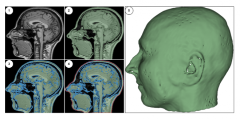
The MRI data consist of foreground objects (in the head region) and background (data-free) voxels. In this section, the process of separating foreground voxels from the background was carried out. Typically, the brightness values of background voxels are within a given range [0-200], while foreground voxels may be scattered across a wider range (such as [0-5000]). Differences in MRI devices, variations in the parameters selected during imaging, and variation in patients' physical characteristics contribute to the wide range of voxel brightness values. All these differences prevent the use of a fixed threshold value for segmenting the head region. Therefore, the dynamic thresholding approach specified in Eq. (1) was used to perform foreground/background separation in the original MR image (see Figure 2(1)).
$\begin{gathered}\text { threshval }=\operatorname{Mean}(\mathrm{MR})+k * \text { StandartDev }(M R) \\ \text { Foreground(Head) }=\mathrm{MR} \geq \text { threshVal } \\ \text { Background }=\mathrm{MR}<\text { threshVal }\end{gathered}$ (1)
The variable k used in Eq. (1) is a coefficient used to limit the effect of standard deviation. In this study, k was chosen as 0,1. It is observed that with this simple proposed dynamic thresholding approach, the head region can be robustly extracted without being affected by the MRI characteristics (modality, resolution, slice thickness, and intensity distribution) (see Figure 2(2)).
Figure 2. Extraction of the external head model: (1) Original MRI, (2) Detection of the head object, (3) Detection of inner and outer boundaries, (4) Detection of the external boundary surface, (5) External surface model of the head
2.1.2 Detection of the external surface of the head
In this stage, the voxels in the inner area of the head object were cleaned, and a suitable external surface model for 3D printer output was obtained. For this purpose, we extracted the inner and outer boundary lines of the two-level head object detected in the previous stage (see Figure 2(3)). The binary contour image filter found in the ITK toolkit was found to be suitable for this operation [20]. After the boundary lines were detected, we observed that a significant amount of the structure within the inner region of the head still needed to be removed (see Figure 2(3)). To clean up these structures and obtain only the boundary line of the external surface, a second operation was performed using the Surface Wrap Solidify [21] plugin found in 3D Slicer. Using the same plugin, outlines of the outer surface of structures can be extracted and given a specified thickness. Through iterative morphological operations, external surfaces can be obtained (see Figure 2(4)). In this study, the thickness of the outer boundary line was set at 1.5 mm. In the final stage, the 3D model transformation of the outer boundary line was performed (see Figure 2(5)), and the corresponding model was saved in an STL file format before being printed out from a 3D printer.
2.1.3 Detection of the facial landmarks on the MRI head model
In this section, the detection of facial landmarks on the 3D head model was undertaken. The Google Mediapipe library was used to detect these landmark points. Since Mediapipe works only on 2D images, a 2D image was first taken from the facial area of the 3D head model and used as an input for the Mediapipe application. Mediapipe detects facial landmarks in a given image and outputs a list containing the (x,y) coordinates of 468 points. To determine the real-world positions of these points on the 3D head model using the 2D image plane, we carried out the transformation process detailed in Algorithm 1. The GetPickedRAS method in Algorithm 1 starts from the given x and y points and progresses along the z-axis, providing the x, y, and z coordinates of the first object it encounters within a specified radius. This transformation utilizes the threeDView object from 3D Slicer, which is used for visualizing 3D objects. After the 3D model positions of the 2D facial points were determined, images of the head model and facial landmarks were obtained, as shown in Figure 3.
|
Algorithim 1. Transformation of 2D facial landmarks to 3D |
|
Input: Point2b, MR Çıktı: Point3b
tDV=slicer.app.layoutManager().threeDWidget(0).threeDView() modelDispManager = tDV.displayableManager() for each, i ∈ len(Point2b) do X = int(Point2b[i].x ∗ MR.width) Y = int(Point2b[i].y ∗ MR.height if modelDispM anager.P ick(X, Y ) then rasPos = modelDispManager.GetPickedRAS() Point3b.append([rasPos[0], rasPos[1], rasPos[2]]) |
Figure 3. Detection of facial landmarks on the MRI and depth head models
Using the MRI data taken from the patient, the head object, external surface model, and facial landmark detection processes were carried out. After segmenting the head object from the MRI, the external surface model of this object was obtained and printed on a 3D printer. Additionally, facial landmarks on the head were detected. In the next section, the details of these sub-operations are explained.
2.2 Depth camera process
At this stage, which is one of the main contributions of the study, the processes of acquiring data from a depth camera mounted on the end of a robotic arm, generating a depth head model, and detecting facial points on the model were performed. The use of a depth camera eliminates the second radiographic imaging procedure in traditional brain-targeting methods, thus reducing the patient's exposure to radiation from radiological imaging. Therefore, the proposed approach will have positive effects through its provision of a shorter and healthier solution, increased patient comfort, and a lesser workload for hospitals.
2.2.1 Detection of 3D face landmarks from RGBD data
At this stage, the Mediapipe library was used to detect 468 points on the RGB image of the patient's face in the RGBD data. Then, with the aid of depth data (D), the detected 2D facial points were transformed into 3D. The transformation approach used for this process is shown in Algorithm 2.
|
Algorithim 2. Transformation of 2D facial points to 3D |
|
Input:Point2d, RGBD.Depth,TCamera,width,height,cx,cy,fx,fy Çıktı: Point3d
for Point in range(Point2d) do u = Point.x * width v = Point.y * height z = RGBD.Depth[u, v] x = (u – cx)* z/fx y = (v – cy) * z/fy point = TCamera * [x, y, z, 1] Point3d.append(point) |
|
end for |
In the algorithm, the variable Point2D represents the 2D facial landmarks obtained using Mediapipe. Additionally, the width and height variables represent the dimensions of the depth image, while the cx and cy variables represent the central point of the image. The fx and fy variables are the camera's horizontal and vertical focal length parameters. The TCamera variable is a transformation matrix representing the position and orientation of the camera relative to the end-effector of the robot arm. This matrix is used to perform 3D transformation based on the camera's position in space. The calculated 3D facial landmarks are multiplied by the TCamera transformation matrix to compute their real-world positions.
Figure 3 shows the facial points obtained using the MRI and depth models. The first row shows the MR head model (green) and the detected facial points (red dots), and the second row shows the head model obtained with the depth camera (yellow) and the facial points detected using the depth matrix.
Upon careful examination of the head models, the MRI head model is smooth and of high quality. In contrast, some holes and undetectable regions (especially in the ear, nose, and lip areas) can be observed in the depth head model. However, due to the holistic approach of the Mediapipe algorithm in detecting the facial model, it can be observed that these small imperfections on the model do not negatively affect the detection of facial landmarks.
2.3 Registration methods
The aim of landmark-based registration methods is to calculate the transformation matrix required to minimize the distance between sets of moving and fixed points. In this study, two different methods were used for landmark-based registration:
In the registration process, the facial landmarks obtained from the depth camera were deemed “fixed”, while those obtained from the MRI data were deemed “moving”. In the singular value decomposition (SVD)-based method, initially, the center points of both sets of facial landmarks (fixed and moving) were set to the point of origin (0,0,0). Thus, we ensured that the two point sets were centered at the same centroid. Then, the rotation angles between the point sets were estimated. To achieve this, we obtained a large square matrix (M) that represents the effect of each moving point on the fixed set by projecting the moving-point set onto the fixed set. By performing singular value decomposition of this 468 x 468 matrix, the eigenvectors (U and V) of the M.MT and MT.M matrices were obtained. Using these matrices containing orthonormal vectors, the rotation matrix (R) was calculated. Finally, the calculation of the transformation matrix was completed by adding the scale and translation coefficients to this matrix. The calculated transformation matrix was applied to the entire moving-point set to obtain the registered point set. We found the SVD-based registration method to be relatively efficient compared to other approaches. The pseudo-code for this method is shown in Algorithm 3.
The second method used for registration is the random forest (RF)-based method [24]. The random forest method, which is based on machine learning, has widespread use in the field. It works by combining the prediction results of multiple decision trees. Each tree is trained independently, and after training, the input data are passed through all the decision trees to obtain the predicted positions; then, the averages are taken. Compared to other methods, the advantages of the RF method are high accuracy, generalizability, and speed. However, this method does require enough data. In this study, the high number of points (468) positively increased the accuracy of the RF method; we thus found it a powerful approach to modeling the relationship between two sets of points. In the study, we used the RandomForestRegressor model from the Scikit-learn Python library. It was observed that the number of decision trees more than 200 did not contribute significantly to the result. Therefore, the number of decision trees was determined as 200.
|
Algorithim 3. SVD-based registration |
|
Input: fixedP, movingP Çıktı: registeredP
movingP = movingP – mean(movingP) fixedP = fixedP – mean(fixedP) M = movingPT * fixedP U, S, V = SVD(M) R = VT. U. V |
|
registeredP = movingP * RT scale = norm(fixedP) / norm(movingP) registeredP = registeredP * scale + mean(fixedP) |
2.4 Robotic application
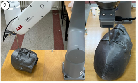
The aim of the robotic application is to guide the tip of a needle, which is mounted at the end of a robotic arm and has known physical properties, to a desired target point on the head prototype. For example, when the tip of the nose was selected from the features of the set of facial landmarks, the goal was for the robotic arm to touch the tip of the needle to the tip of the nose on the head prototype. A registration matrix was used to accurately guide the robotic arm. The RF method detailed in the previous section was able to successfully calculate this matrix.
In this study, the CRB 15000-5/0.95 robot arm model from ABB company was utilized. Figure 4 shows the robot arm and the coordinate systems it utilizes. The robot has a 6-axis structure and can be categorized as a COBOT (collaborative robot). This is because, unlike standard robots, it has actuators that can measure torque with high precision in all axes. This makes COBOT suitable for operation alongside humans, which is why it was chosen for this study. The robot's repeatability is 0.02 mm, and its reach distance is 950 mm. The end effector of the robot can reach speeds of up to 2.2 m/s.
Figure 4. Robot and reference frames
The robot has two different reference frames, TBase and TFlans. Before robot movements are executed, position information is transformed into the TBase reference frame and then used. It is generally assumed that TBase = [0,0,0]. In this study, the camera and end effector have two different reference frames, named TCamera and TTool, respectively. The image taken from camera and the generated point cloud are determined with respect to the TCamera reference frame. However, the robot should be moved with respect to the TTool frame. Therefore, all transformations should be converted to the robot's TBase frame before use. The basic transformation matrices used in this study were calculated as shown in Eq. (2) and Eq. (3). Finally, the needle length to be used was added to the Z-axis and subjected to translation operation.
${}_{Flans}^{Base}T={{T}_{Base}}\times {{T}_{Trans\left( x=300,~y=0,~z=450 \right)}}\times {{T}_{Rot\_y\left( 180{}^\circ \right)}}$ (2)
${}_{Cam}^{Base}T={}_{Flans}^{Base}T\times {{T}_{Trans\left( x=-57,5,~y=0,~z=29 \right)}}\times {{T}_{Rot\_z\left( 180{}^\circ \right)}}$ (3)
$\begin{aligned} T_{\text {Base }} & =\left[\begin{array}{llll}1 & 0 & 0 & 0 \\ 0 & 1 & 0 & 0 \\ 0 & 0 & 1 & 0 \\ 0 & 0 & 0 & 1\end{array}\right], \\ T_{\text {Flans }} & =\left[\begin{array}{cccc}-1 & 0 & 0 & 300 \\ 0 & 1 & 0 & 0 \\ 0 & 0 & -1 & 450 \\ 0 & 0 & 0 & 1\end{array}\right], \\ T_{\text {Cam }} & =\left[\begin{array}{cccc}1 & 0 & 0 & 357,5 \\ 0 & -1 & 0 & 0 \\ 0 & 0 & -1 & 421 \\ 0 & 0 & 0 & 1\end{array}\right]\end{aligned}$ (4)
As shown in Figure 5, we used socket programming between the robot and the developed software. The robot can communicate bidirectionally via Python socket programming over the TCP/IP protocol. After registering the MRI and camera images, the resulting transformation matrix enables precise targeting of the robot to the marked positions in the MRI.
Figure 5. The flow diagram of socket programming used between the developed software and the robot
3.1 Preparing dataset
In this study, we used ADNI [25], which is a publicly available dataset. Firstly, two patients (Patient 8 and Patient 10) were selected from the ADNI dataset. The MRI and depth camera processes were performed sequentially on each set of patient data. During MRI procedures, extraction of the automatic head object (MHead) and detection of facial points were carried out. Additionally, the 'Extraction of the External Head Surface Model' process was applied to the MRHead model, resulting in the removal of interior parts and the generation of a 3D-printed output. The printed hollow head model was fixed on a table, and RGBD data were obtained using a depth camera (Intel RealSense d435) mounted on the robot arm. A 3D point cloud was created from the RGBD data, and then it was converted into a surface model to obtain the depth head (DHead) model. Facial landmarks on the DHead were obtained in a similar manner to those on the MRHead. During the checks, no issues were observed with the points on the MRHead. However, abnormal shifts in the locations of facial landmarks detected on the DHead, along with instances in which the model structure protruded, were noted. The presence of a small number of unmeasurable pixel values in the depth matrix (which contain NaN values) is the reason for this. When the position of the facial landmarks detected by Mediapipe coincided with such a pixel, the locations of the points shifted abnormally. Hence, we conducted the detection and removal of points displaying abnormal shifts within the point sets, followed by an assessment of their impact on the registration process. For this purpose, the results of two different conditions within the registration process (original facial landmarks and the filtered version with abnormal points removed) are presented in the following tables.
Registration processes were performed, and we analyzed the effect of different facial landmarks on said processes. For this purpose, four different combinations of landmark sets were created, as shown in Table 1.
Table 1. Landmark sets used in registration
|
|
Face Area |
Landmark Count |
|
Set 1 |
All |
468 |
|
Set 2 |
Silhouette of the face |
36 |
|
Set 3 |
Eye, eyebrow, mouth, nose, cheek |
181 |
|
Set 4 |
Silhouette, eye, eyebrow, mouth, nose, cheek |
217 |
3.2 Registration results
The registration process was carried out in two different ways, both using the original point set combinations and excluding the anomalous points. To accurately evaluate the registration performance, three different metrics were calculated: root mean squared error (RMSE), fiducial registration error (FRE) and correlation coefficient. The registration results for Patient 8 from the ADNI dataset are presented in Table 2, while the registration results for Patient 10 are presented in Table 3.
In addition to the results shown in Table 2 and Table 3, the lowest TRE values for both patients were obtained with the RF method on Set1. These values were calculated as 2.217 mm and 2.164 mm for each patient, respectively.
Upon examining Table 2 and Table 3, which contain the registration results, removing anomalous points from the point sets significantly improved the registration accuracy. For example, when examining the registration performance of Set1's points using the SVD method, as shown in Table 1, the original point set results in a high FRE value of 394.0313. However, after removing anomalous points from the set, the FRE value significantly decreases to 6.788. This situation clearly demonstrates the impact of eliminating anomalous points on the registration. However, when we examine the results in Tables 2 and 3 together, the following question can be answered conclusively: "Which set of points provides high registration accuracy?". Accordingly, Set1's combination of points, in which all facial landmarks are used, provides the highest registration accuracy. On the other hand, Set2 provided less registration accuracy: its number of landmarks is lowest, and its number of anomalous landmarks is highest. Furthermore, upon careful examination of the results, we observed that the RF method outperforms SVD in registration accuracy across all set combinations.
For comparison, in a landmark-based 3D head model registration study [26], an RMSE error of less than 3 mm was achieved, and this error was reported to be acceptable. In another study [27], which compared the effect of skin markers (SM) and natural markers (NM) on registration and used real neurosurgery patient data, an RMSE of 3.2 mm was reported when using NM, and 2.9 mm when using SM. In the study [28] that measured the effect of the number of landmarks (LM) on surgical navigation accuracy, different TRE values ranging from 1.63 to 2.06 were calculated, and it was reported that there is no linear relationship between FRE and TRE. In another study [29], which measured the performance of a commercial MRI registration application, it was reported that the TRE error between two points after rigid, whole-volume registration was calculated as 1.6 mm.
The registration results achieved using the SVD and RF methods for both patients are visually presented in Figure 6. Facial landmarks obtained from the depth camera data (fixed) are shown in red, while those obtained from the MR data (moving) are shown in blue. The first column shows the data for Patient 8, while the second column shows the data for Patient 10.
Table 2. Registration results for Patient 8
|
|
With Abnormal Points |
Without Abnormal Points |
|||||
|
Initial |
SVD |
RF |
Initial |
SVD |
RF |
||
|
Set 1 |
RMSE |
227.494 |
23.861 |
7.787 |
227.025 |
3.919 |
0.943 |
|
FRE |
394.0313 |
41.328 |
13.487 |
393.219 |
6.788 |
1.633 |
|
|
Correlation |
0.113 |
0.784 |
0.986 |
0.273 |
0.951 |
0.998 |
|
|
Set 2 |
RMSE |
227.494 |
30.849 |
24.819 |
227.025 |
7.817 |
7.696 |
|
FRE |
394.0313 |
53.432 |
42.988 |
393.219 |
13.539 |
13.330 |
|
|
Correlation |
0.709 |
0.739 |
0.709 |
0.273 |
0.932 |
0.934 |
|
|
Set 3 |
RMSE |
227.494 |
22.809 |
22.241 |
227.025 |
4.211 |
3.977 |
|
FRE |
394.0313 |
39.506 |
38.522 |
393.219 |
7.294 |
6.888 |
|
|
Correlation |
0.113 |
0.768 |
0.773 |
0.273 |
0.943 |
0.944 |
|
|
Set 4 |
RMSE |
227.494 |
23.425 |
21.829 |
227.025 |
3.995 |
3.943 |
|
FRE |
394.0313 |
40.574 |
37.810 |
393.219 |
6.920 |
6.829 |
|
|
Correlation |
0.113 |
0.781 |
0.788 |
0.273 |
0.950 |
0.951 |
|
Table 3. Registration results for Patient 10
|
|
With Abnormal Points |
Without Abnormal Points |
|||||
|
Initial |
SVD |
RF |
Initial |
SVD |
RF |
||
|
Set 1 |
RMSE |
205.099 |
19.711 |
7.114 |
205.571 |
3.734 |
0.879 |
|
FRE |
355.242 |
34.140 |
12.322 |
356.060 |
6.467 |
1.523 |
|
|
Correlation |
0.083 |
0.784 |
0.985 |
0.084 |
0.965 |
0.999 |
|
|
Set 2 |
RMSE |
205.099 |
33.386 |
22.389 |
205.571 |
6.019 |
4.780 |
|
FRE |
355.242 |
57.826 |
38.779 |
356.060 |
10.425 |
8.280 |
|
|
Correlation |
0.083 |
0.602 |
0.708 |
0.084 |
0.956 |
0.959 |
|
|
Set 3 |
RMSE |
205.099 |
18.372 |
18.359 |
205.571 |
3.947 |
3.914 |
|
FRE |
355.242 |
31.821 |
31.799 |
356.060 |
6.836 |
6.779 |
|
|
Correlation |
0.083 |
0.781 |
0.783 |
0.084 |
0.962 |
0.963 |
|
|
Set 4 |
RMSE |
205.099 |
19.049 |
18.496 |
205.571 |
3.763 |
3.631 |
|
FRE |
355.242 |
32.994 |
32.036 |
356.060 |
6.518 |
6.289 |
|
|
Correlation |
0.083 |
0.775 |
0.776 |
0.084 |
0.964 |
0.965 |
|
Figure 6. Registration results (blue: MR landmarks, red: depth landmarks). (1) Patient 8: initial position. (2) Patient 10: initial position. (3) Patient 8: SVD result. (4) Patient 10: SVD result. (5) Patient 8: RF result. (6) Patient 10: RF result
The initial positions of the facial landmarks are shown in the first row (Figure 6(1) and Figure 6(2)). At this stage, when registration had not yet been performed, the fixed and moving landmarks exhibited significant differences in terms of rotation, scale, and translation. Moreover, when addressing the red-colored facial landmarks in Figure 6(1), it is clearly visible that there are abnormal points extending beyond the silhouette of the face. The second row shows the registration results of the SVD method for both patients. When examining the lip area in Figure 6(4), there is a significant registration error. The third row shows the registration results of the RF method for both patients. As depicted in Figure 6(6), the points in the lip area overlap significantly better compared to the results of the SVD method. These results demonstrate that the RF-based method is a reasonable approach to the registration of facial landmarks.
Figure 7. Targeting the robot to the tip of the nose. (1) Selection of target point (red) (2) Real-world environment
Figure 7(1) shows the selection of the nose tip point (red). Since this point is calculated with respect to the robot's reference frame, the robot is directed to the specified point without requiring any additional action. As shown in Figure 7(2), the robot targeted the specified point with high accuracy. In the second targeting task, the midpoint of the patient's forehead was selected (see Figure 8(1)). The robotic arm was directed to the selected point with similar precision (see Figure 8(2)).
Figure 8. Targeting the robot to the midpoint of the forehead. (1) Selection of target point (red) (2) Real-world environment
The success of our activities, as detailed herein, instilled us with confidence in the potential of the robotic arm to be used in advanced medical procedures such as brain targeting, thereby fueling our motivation to carry out further research in this area. We will of course strive to minimize risk in reaching target points within sensitive organs such as the brain. The authors will continue their work on predicting and minimizing possible computational risks.
In this study, high accuracy was achieved in calculations performed for the case of two sample patients. Such a result was confirmed when we directed the robot to targeted regions following registration. In doing so, we observed that the detection of landmarks and the registration process could be completed within a time frame suitable for surgical procedures. The system can execute the radiological imaging process in a single procedure and automatically obtains a large number of landmarks (e.g., 468). However, its limitations require further discussion. In this study, deformations---which may occur affect the patient's face between the MRI and registration---were not accounted for. In additional, we have not yet evaluated the system's accuracy when working with patients with different skin tones, skin textures, and facial hair; this is an area of interest that will be probed in future studies. In this study, tests were conducted on two patient samples. Increasing the number of tests performed and evaluating their results would serve to reinforce our results concerning the system's accuracy. Moreover, it would be interesting to test the system's performance using depth camera images of patients who have had MRI scans (instead of the depth head model obtained from the MRI images). Finally, comparing performances using different registration methods will be a further important step in identifying the most accurate approach to this critical process.
Traditional deep brain-targeting systems are used to accurately pinpoint critical areas within the brain. These systems typically use two different scans (MRI and CT). Additionally, neurosurgeons perform thorough and detailed examinations of these scans, manually identifying anatomical points. The accuracy of the MRI-CT registration process can be compromised by factors such as insufficient scan quality, lack of sufficient experience on the part of the surgeon, and errors in manual marking. This situation hinders our ability to accurately reach the targeted point.
In this paper, we propose an alternative targeting approach to eliminate the shortcomings of the traditional targeting method. During this approach, depth camera data obtained from the patient's facial region are used along with the MRI data. Thanks to this use, the patient is prevented from being exposed to radiological imaging twice. Additionally, the proposed approach overlays a facial mask containing 468 points (MHead and DHead) onto the MRI and depth data instead of manually marking anatomical points. In the next step, the registration of these masks is performed using singular value decomposition (SVD) and random forest methods to calculate the transformation matrix. In the last step, a robot arm in a real-world environment is provided with precise access to the desired point on the patient's head. In our experimental study, the ADNI dataset was used, and we observed that the robot arm could reach targeted points with great accuracy.
This study was supported by the Scientific and Technological Research Council of Turkey (TÜBİTAK) (Grant No.: 123E280). We acknowledge TÜBİTAK for its support of the project.
[1] Zanello, M., Carron, R., Peeters, S., Gori, P., Roux, A., Bloch, I., Pallud, J. (2021). Automated neurosurgical stereotactic planning for intraoperative use: A comprehensive review of the literature and perspectives. Neurosurgical Review, 44: 867-888. https://doi.org/10.1007/s10143-020-01315-1
[2] Rainer, G. https://www.brainvoyager.com/bv/doc/UsersGuide/BrainVoyagerUsersGuide.html, accessed on Apr. 12, 2024.
[3] Ulutabanca, H. (2021). Deep brain stimulation: New techniques and technologies. Parkinsonism Relat Disord, 31(3): 343-347. https://doi.org/10.1016/S1353-8020(13)70045-2
[4] Piano, C., Bove, F., Mulas, D., Bentivoglio, A.R., Cioni, B., Tufo, T. (2021). Frameless stereotaxy in subthalamic deep brain stimulation: 3-year clinical outcome. Neurological Sciences, 42: 259-266. https://doi.org/10.1007/s10072-020-04561-9
[5] He, Z., Zhu, C.X.L., Chan, D.T.M., Cheung, T.C.Y., Ng, H.K., Mok, V.C.T., Poon, W.S. (2024). Diagnostic accuracy and field for improvement of frameless stereotactic brain biopsy: A focus on nondiagnostic cases. Journal of Neurological Surgery, 85(1): 48-61. https://doi.org/10.1055/a-1994-8033
[6] Braga, H.M., Dellaretti, M.A., Faria, M.P., Almeida, J.C.D., Nascimento, L.M.D. (2023). Accuracy comparison between frameless biopsy and frame-based biopsy: A retrospective study of a case series. Arquivos Brasileiros de Neurocirurgia: Brazilian Neu-rosurgery, 42(3): e233-e238. https://doi.org/10.1055/s-0043-1775556
[7] Ungar, L., Nachum, O., Zibly, Z., Wohl, A., Harel, R., Attia, M., Cohen, Z.R. (2022). Comparison of frame-based versus frameless image-guided intracranial stereotactic brain biopsy: A retrospective analysis of safety and efficacy. World Neurosurgery, 164: e1-e7. https://doi.org/10.1016/j.wneu.2021.07.063
[8] Wu, S., Wang, J., Gao, P., Liu, W., Hu, F., Jiang, W., Shu, K. (2021). Comparison of the efficacy, safety, and duration of frame-based and Remebot robot-assisted frameless stereotactic biopsy. British Journal of Neurosurgery, 35(3): 319-323. https://doi.org/10.1080/02688697.2020.1812519
[9] Hiremath, G.K. (2020). Robotic deep brain stimulation (R-DBS)-“awake” deep brain stimulation using the NeuroMate robot and O-arm. Neurology India, 68(Suppl 2): 328-332. https://doi.org/10.4103/0028-3886.302450
[10] Neudorfer, C., Hunsche, S., Hellmich, M., El Majdoub, F., Maarouf, M. (2018). Comparative study of robot-assisted versus conventional frame-based deep brain stimulation stereotactic neurosurgery. Stereotactic and Functional Neurosurgery, 96(5): 327-334. https://doi.org/10.1159/000494736
[11] Paff, M., Wang, A.S., Phielipp, N., Vadera, S., Morenkova, A., Hermanowicz, N., Hsu, F.P. (2020). Two-year clinical outcomes as-sociated with robotic-assisted subthalamic lead implantation in patients with Parkinson's disease. Journal of Robotic Surgery, 14: 559-565. https://doi.org/10.1007/s11701-019-01025-x
[12] IFR, World Robotics. https://ifr.org/ifr-press-releases/news/robot-sales-rise-again, accessed on Apr. 10, 2024.
[13] Wightman, S.C., David, E.A., Atay, S.M., Kim, A.W., Angelos, P. (2020). The ethics of robotic surgical systems is a conversation of informed consent. Video-Assisted Thoracic Surgery, 5. http://doi.org/10.21037/vats.2020.02.02
[14] Bansal, E., Kunaprayoon, S., Zhang, L.P. (2023). Opportunities for global health diplomacy in transnational robotic telesurgery. AMA Journal of Ethics, 25(8): 624-636. http://doi.org/10.1001/amajethics.2023.624
[15] Pai, S.N., Jeyaraman, M., Jeyaraman, N., Nallakumarasamy, A., Yadav, S. (2023). In the hands of a robot, from the operating room to the courtroom: The medicolegal considerations of robotic surgery. Cureus, 15(8). http://doi.org/10.7759/cureus.43634
[16] Nathoo, N., Çavuşoğlu, M.C., Vogelbaum, M.A., Barnett, G.H. (2005). In touch with robotics: Neurosurgery for the future. Neurosurgery, 56(3): 421-433. https://doi.org/10.1227/01.NEU.0000153929.68024.CF
[17] BrainLab. https://www.brainlab.com/surgery-products/overview-neurosurgery-products/cranial-navigation/, accessed on Apr. 16, 2024.
[18] Mediapipe. https://ai.google.dev/edge/mediapipe/solutions/guide?hl=en, accessed on Dec. 16, 2023.
[19] Faraji, A.H., Kokkinos, V., Sweat, J.C., Crammond, D.J., Richardson, R.M. (2020). Robotic-assisted stereotaxy for deep brain stimulation lead implantation in awake patients. Neurosurgery, 19(4): 444-452. https://doi.org/10.1093/ons/opaa029
[20] Lehmann, G. https://www.insight-journal.org/browse /publication/217, accessed on Jan. 11, 2024.
[21] Weidert, S., Andress, S., Linhart, C., Suero, E.M., Greiner, A., Böcker, W., Becker, C.A. (2020). 3D printing method for next-day acetabular fracture surgery using a surface filtering pipeline: Feasibility and 1-year clinical results. International Journal of Computer Assisted Radiology and Surgery, 15: 565-575 https://doi.org/10.1007/s11548-019-02110-0
[22] Arun, K.S., Huang, T.S., Blostein, S.D. (1987). Least-squares fitting of two 3-D point sets. IEEE Transactions on Pattern Analysis and Machine Intelligence, 5: 698-700. https://doi.org/10.1109/TPAMI.1987.4767965
[23] Sokooti, H., Saygili, G., Glocker, B., Lelieveldt, B., Staring, M. (2016). In medical image computing and computer-assisted intervention-MICCAI 2016. In 19th International Conference, Athens, Greece. https://doi.org/10.1007/978-3-319-46726-9_13
[24] Breiman, L. (2001). Random forests. Machine Learning, 45: 5-32. https://doi.org/10.1023/A:1010933 404324
[25] ADNI Dataset, https://adni.loni.usc.edu/, accessed on Sep. 25, 2023.
[26] Schlesinger, O., Kundu, R., Isaev, D., Choi, J.Y., Goetz, S.M., Turner, D.A., Sapiro, G., Peterchev, A.V., Di Martino, J.M. (2024). Scalp surface estimation and head registration using sparse sampling and 3D statistical models. Computers in Biology and Medicine, 178: 108689. https://doi.org/10.1016/j.compbiomed.2024.108689
[27] Wolfsberger, S., Rössler, K., Regatschnig, R., Ungersböck, K. (2002). Anatomical landmarks for image registration in frameless stereotactic neuronavigation. Neurosurgical Review, 25: 68-72. https://www.doi.org/10.1007/s10143-001-0201-x
[28] Javer, A., AlQunaee, M., Kolahi, A. (2020). Relationship between Target Registration Error (TRE) and Fiducial Registration Error (FRE), a clinical study and statistical analyses.
[29] Lin, J.S., Fuentes, D.T., Chandler, A., Prabhu, S.S., Weinberg, J.S., Baladandayuthapani, V., Hazle, J.D., Schellingerhout, D. (2017). Performance assessment for brain MR imaging registration methods. American Journal of Neuroradiology, 38(5): 973-980. https://doi.org/10.3174/ajnr.A5122