© 2018 IIETA. This article is published by IIETA and is licensed under the CC BY 4.0 license (http://creativecommons.org/licenses/by/4.0/).
OPEN ACCESS
This paper attempts to reconstruct the 3D model of buildings based on the information of building components and internal space in the floor plan. For this purpose, a pre-processing algorithm was designed to eliminate the redundancy lines in the floor plan. Then, the window and door extraction methods were put forward to obtain the parameters of building components and restore the wall integrity. After that, the internal subspace was detected through the closed-loop self-check algorithm. Finally, the proposed reconstruction method was verified through a case study on a hotel floor plan. The results show that our method can effectively reconstruct 3D models of buildings in smart cities.
floor plan, building components, space subdivision, 3D model reconstruction
With the development of smart cities, there is an increasing demand for the production of 3D building models (Batty et al., 2012; Caragliu et al., 2012). 3D building models are applicable to many scenarios, such as indoor map making (Philipp et al., 2014), emergency response (Hosna et al., 2015) and ventilation analysis. Compared to 2D maps, 3D building models are intuitive and visual, and contain topology and semantic information. Therefore, 3D building model library is essential to the construction of smart cities (Goodchild, 2009).
The existing 3D model building methods roughly rely on three things: 3D range sensor (Chhatkuli et al., 2015), multiple images (Kolev et al., 2012), and floor plans. The first two kinds of methods are mainly used to establish a simple model for building envelope, which contains no structure or information of the indoor space and falls short of the precision required for indoor space analysis. Hence, these two methods are not suitable for automatic building of large-scale 3D indoor models. As its name suggests, the floor plan-based method identifies and extracts the building components from the floor plan, and realizes the 3D reconstruction of the target building. This method boasts richer data sources, better accuracy and lower cost than the other two methods.
Much research has been done on the modeling of buildings. For example, S. Horna proposed a formal representation of consistency constraints dedicated to building interiors and associated with a topology model, and applied the model to identify building artificiality (Horna et al., 2009). Ah-Soon & Tombre, (2001) put forward a network for component detection and recognition in scanned architectural drawings. Zhang & Liu, (2007) proposes a descriptor based on symbolic signatures for symbol filtering and recognition, which analyses the line-arc relationship and uses vector signature to simplify the identification process. With the introduction of Shape-opening graphs, Zhu et al. (2014) recognized structural components, depicted the relationship between components and openings (i.e. the interspace between components), and generated 3D models by extruding loops to the wall height and cutting openings from the walls. Gimenez et al. (2016) extracted indoor space information through the expansion of the bounding box surrounding the text element, and recognized the text content. Domínguez et al. (2012) introduces the wall adjacency graph (WAG) to detect walls from sets of planar segments contained in architectural floor plans and presents algorithms for the detection of joint points and wall intersection points. This method can detect the topology of building floors semi- automatically.
To sum up, the above studies have extracted and analyzed 2D building information in varying degrees, laying the basis for 3D building reconstruction. Due to the data complexity of CAD drawings, however, it is difficult to apply the existing data extraction and analysis methods to all floor plans. The existing 2D image information extraction methods are concentrated on the identification of 2D images and the establishment of topological relations. There are only a very few reports on the comprehensive method involving data pre-processing, information extraction, data storage and data expression. To make up for the gap and perfect the 3D modeling technology for actual production, this paper designs a 3D building modeling method based on CAD floor plans. The method covers the whole process from raw data extraction to 3D scene construction.
This paper is organized in 8 sections. Main process of the method is summarized in Section 2. Section 3 introduces the requirements of data preprocessing and overlapping wall line elimination algorithm. In Section 4, we describe window and door extraction method to get the parameters of building components. Then, in Section 5, we restore the wall integrity by using the parameters extracted previously. After that, closed loops consisting of wall lines were identified to subdivide floor space in Section 6. Experimental results are shown in Section 7. Finally, we conclude the paper in Section 8.
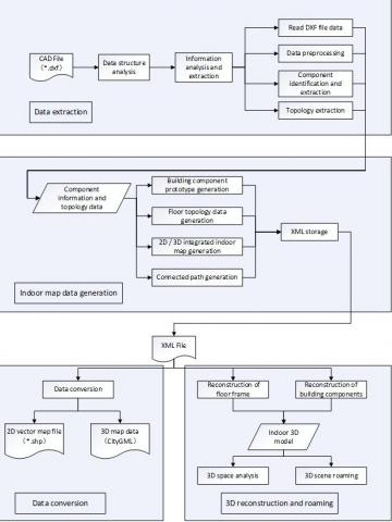
Figure 1. The flowchart of the 3D building modeling method based on CAD floor plans
Fig.1 is the flowchart of the 3D building modeling method based on CAD floor plans. This method has four main modules, including the data extraction module, the indoor map data generation module, the data conversion module and the 3D reconstruction and roaming module. The modeling is achieved in the following steps.
(1) Enter the data extraction module, and extract the building information from CAD floor plans. Preprocess the information so that it could be handled in the component identification and extraction algorithm. The main steps that need to be executed are storing different components in hierarchies, topology check and eliminate the overlapping wall lines.
(2) Import the pre-processed data into the algorithms. Through the component recognition algorithms, the building components are extracted from the CAD floor plans; through the wall integrity restoration algorithm, holes in the wall caused by doors and windows are restored. On this basis, the sub-space information can be extracted.
(3) Generate the topological relations based on the sub-space information and component information. Then, produce 3D indoor maps and connected paths in the indoor map generation module.
(4) Save these data and information as XML files, and it can be converted into .shp format, the most common format in Geographic Information System (GIS) in the data conversion module. The .shp files can be imported to GeoDataBase and further spatial analysis can be carried out. By mapping relations, the data in the XML file can also be converted to CityGML format, a general data model for 3D City templates presented by Open Geospatial Consortium (OGC).
(5) Enter the 3D reconstruction and roaming module, the floor frame and building components can be reconstructed by using the extracted building information. Through the combination of them, a 3D model of the building can be generated. Using this automatically generated model, 3D roaming and 3D analysis can be applied.
3.1. The necessity of data Pre-processing
With countless symbols, annotations and fillers, a CAD floor plan is definitely not an easy target of data identification and extraction. What is worse, many drawings fail to meet cartographic specifications. In many cases, different building components are incorrectly placed in the same layer or randomly attributed to various layers.
Therefore, to meet the requirements, the data on CAD floor plans must be pre-processed prior to data analysis and extraction. The different components should be stored in hierarchies, the topology in errors should be corrected, and the entities should be checked against the specifications.
3.2. Classification of building components
The method designed in this paper takes the cad building plan in dxf format as the raw data, and the data needs to meet the following two requirements: first, different types of elements need to be drawn in layers according to cad drawing design specifications; second, the elements of doors and windows should be presented in block form. Therefore, the first pretreatment task is to classify of building components and establish the mapping relationship manually between layer names and different types of elements (wall, door, window, annotation, etc.).
3.3. Elimination of overlapping wall lines
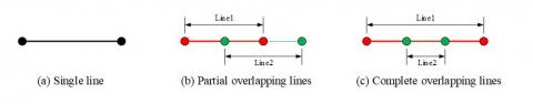
Topology errors are commonplace in most CAD drawings, because it is inevitable for cartographers to make mistakes. As shown in Fig.2(b) and 2(c), Line 1 and Line 2 are partially or entirely overlapped.
Figure 2. Partial or complete overlapping wall lines
Algorithm 1: Overlapping wall line elimination algorithm
Algorithm: Overlapping wall line elimination algorithm
Input: Building plans files in DXF format
Output: Building plans files without overlapping wall lines
1. begin
2. generated Lines ←∅; // Define an empty set to store the merged result
3. wallLines ← lines(DXF); // Wall line collection extracted from DXF files
4. list_wall Lines ←cluster(wall Lines); /*Clusters all the segments in the WallLines collection by slope */;
5. for each group_lines in list_walllines
6. if group_lines contains more than 1 line segment then
7. for each line1 in group_lines
8. if line1 not marked then
9. Mark line1 as checked;
10. for each line2 in group_lines
11. if line2 not marked then
12. In both ends of the line1, set the point farther from
13. the midpoint of line2 as point p;
14. In both ends of the line2, set the point farther from
15. the point p as point q;
16. Set the line segment formed by the connection
17. point p and q as line3;
18. if line3 // line1 && the length of line3 <= the sum
19. of the lengths of line1 and line2 then
20. Mark line1 and line2 as removed;
21. Add line3 to collection generatedLines;
22. end if
23. end if
24. end for
25. end if
26. end for
27. end if
28. end for
29. Remove all the line segments in the wall lines marked as removed;
30. Add the line segments in the generatedLines to wallLines;
31. Return
32. end
The overlapping wall lines must be corrected, or they will render building components and walls unrecognizable. Hence, the author designed an algorithm to eliminate overlapping wall lines
4.1. Window extraction
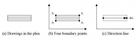
There are many kinds of windows in floor plans, ranging from fixed window, rotating window to sliding window. As shown in Fig.3(a), these windows are often expressed as four or five parallel lines in floor plans. Here, the location and length of each window are determined by extracting the four boundary points of the window blocks. The basic geometric information of a window was derived based on the coordinates of the window length (Fig.3(b)). Besides, the author extracted the vector containing the window length and orientation information from points P1~P4, and called it the direction line (Fig.3(c)). The direction line represents the parameter information of the window in 3D building model.
Figure 3. Window components extraction
4.2. Door extraction
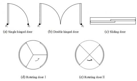
Unlike windows, different types of doors are illustrated very differently in floor plans (Fig.4). The type of door can be determined by counting the number of arcs and circles in each door block.
Figure 4. Different types of doors in building plan
(1) If a block contains an arc but no circle, it is a single hinged door. As shown in Fig.4(a), the circular point of the arc segment was extracted as point P1 and the end of the arc that is not connected to point P1 was extracted as point P2.
(2) If a block contains two arcs but no circle, it is a double hinged door. As shown in Fig.4(b), the coordinates of the center point of the two arcs were extracted and denoted as point P1 and point P2, respectively. If a block contains no arc or circle, it is a sliding door. For this type of door, the extraction method is similar to that for window. The four boundary points were extracted to determine the door information.
(3) If a block contains one circle or more than two arcs, it is a revolving door. For this type of door, the arc or circle center was taken as point P1, the wall line closet to the center was selected, and vertical line was drawn from the center. Then, the pedal point was set as point P2. The vector from P1 to P2 was defined as the direction line of this block. The direction line represents the parameter information of the door in the 3D building model.
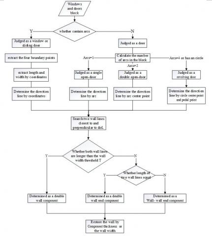
Because the extraction methods of sliding doors and windows are similar, this paper designs an algorithm to identify the two components simultaneously. The flowchart is shown in Fig.5.
Figure 5. The flowchart of window and door extraction algorithm
After the extraction of building components, each room in floor plans is represented as a non-closing polygon consisting of discrete wall lines. Such a polygon is not suitable for the detection of room or the generation of topological relationship between rooms. This calls for the restoration of wall integrity. In other words, the wall lines cut off by doors and windows should be extracted and restored, such that each room becomes a closed, independent polygon. This is a prerequisite for 3D reconstruction of the wall. The process of wall restoration is specified in Fig.6.
5.1. Restoration of window and door openings
No matter it is cut off by a door or a window, the wall line is always cut into a pair of parallel ends. In light of this, the window and door openings on the wall were handled by the same algorithm. In previous sections, both the windows and doors are extracted by the vector direction line containing the length and orientation information. Therefore, the wall lines on the left and right of the vector direction line were identified to restore the integrity of the wall.
Figure 6. End-to-end opening
Figure 7. End-to-wall opening
Figure 8. Wall-to-wall opening
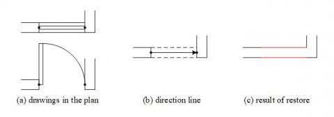
Except for revolving doors, the openings of doors and windows were divided into three categories: end-to-end opening (Fig.6(b)), end-to-wall opening (Fig.7(b)), and wall-to-wall opening (Fig.8(b)). In the end-to-end opening, the length of left wall line and that of the right wall line are the same as wall thickness; in the end-to-wall opening, the length of left wall line still equals wall thickness, but the length of right wall line is far greater than wall thickness; in the wall-to-wall opening, the length of both left and right wall lines are much greater than wall thickness.
After determining the specific type of door and window opening, the author introduced the wall thickness threshold T to help restore the wall line. For end-to-end openings, the wall lines on the two sides were extended and merged directly; for the end-to-wall openings, the wall lines on the end side were extended and intersect the wall on the other side; for the wall-to-wall opening, the wall line was restored based on the door/window width or wall thickness. The wall restorations of the three kinds of openings are separately shown in Fig.6(c), 7(c) and 8(c).
5.2. Restoration of revolving door opening
Unlike windows and the other types of doors, revolving doors are represented by arcs and line segments in CAD floor plans. Therefore, a separate algorithm was designed for restoring the opening of revolving doors. The revolving door opening was regarded as an end-to-end opening, for neither side of the door completely fits in with the wall in the actual design.
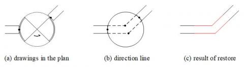
As shown in Fig.9(a), the revolving door may be designed between unparalleled wall lines. Hence, the parallel and unparalleled situations were treated differently. If the two wall ends are parallel to each other, a pair of parallel segments should be created at the opening to link up the wall lines on both sides. If the two wall ends are not parallel to each other (Fig.9(a)), both sides of each wall end should be extended until the two pairs of extension lines meet each other (Fig.9(b) and 9(c)).
Figure 9. Revolving door opening with unparalleled wall ends
After restoring wall integrity, the walls of a room can be expressed as a collection of segments connected end to end. These closed loops, which represent the wall lines, separate each room into an independent polygon. Coupled with the location information of windows and doors, these polygons help to subdivide the floor space and identify the topological relationships between different rooms. Before generating the topology, the author designed a closed loop self-check algorithm to inspect the extraction results. In the algorithm, the number of closed polygons, non-closing polygons and isolated wall lines is respectively denoted as a, b and c. There are two evaluation indices: the number of errors and the number of warnings. The self-check was implemented as follows:
Table 1. The evaluation index of closed LOOPS self-check algorithm
|
Full polygons (a) |
Non-closing polygons (b) |
Isolated wall lines (c) |
Evaluation index |
Program flow |
|
|
Error |
Warning |
||||
|
0 |
0 |
\ |
1 |
c |
Forced checking |
|
\ |
>0 |
\ |
b |
c |
Forced checking |
|
>0 |
0 |
>0 |
b |
c |
Recommended checking |
|
>0 |
0 |
0 |
b |
c |
No need to check |
(1) Set a as the number of full polygons; Set b as the number of non-closing polygons; Set the c as the number of isolated wall lines.
(2) If a=b=0, set the number of error to 1, the user must perform a self-check
(3) If b>0, the user must perform a self-check, and correct all errors before entering the next process;
(4) if c>0, the user can either perform a self-check or ignore the prompt.
(5) if a>0 and b=c=0, the user can move directly to the next process.
The room space structure was created after space subdivision. Fig.10(a) and 10(b) are the drawings on room space structure before and after the subdivision.
(a) Original drawing
(b)Post-subdivision drawing
Figure 10. Drawings on room space structure before and after the subdivision
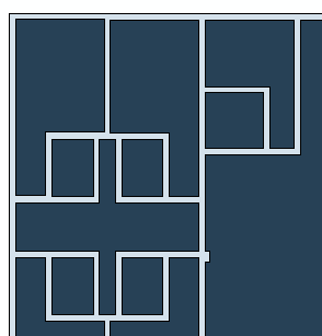
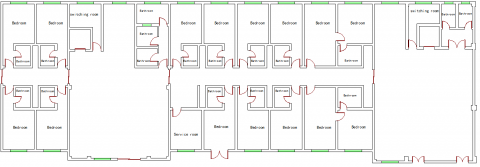
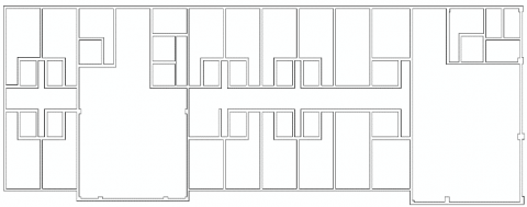
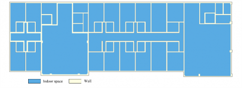
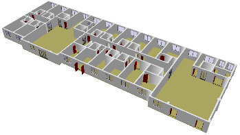
The CAD floor plan of a hotel was selected to verify the effect of our method (Fig.11). The wall thickness threshold T was set to 240mm. Fig.12~Fig.14 display the results of structure extraction and 3D reconstruction. In total, the drawing contains 50 windows, 37 doors. All these components can be identified clearly in the drawing. After restoration of wall integrity, the entire floor space was divided into individual polygons by wall lines (Fig.12). As shown in Fig.13, the rooms are detected as closed polygons after space subdivision, and the semantic information can be extracted by annotation. Overall, it took a very short time to establish the indoor 3D model based on the extracted components and subdivided space. It can be seen from Fig.14 that the indoor 3D scene was preliminarily restored.
Figure 11. CAD floor plan of a hotel
Figure 12. Results of wall integrity restoration
Figure 13. Results of space subdivision
Figure 14. Results of 3D building reconstruction
Taking the floor plan as the data source, this paper presents a method to extract information on building components and indoor space from CAD floor plans. First, a pre-processing algorithm was design to eliminate the overlapping lines in the floor plans. Then, the common components like windows and doors were identified and extracted one by one. Next, the window and door openings were filled up to restore wall integrity. After that, a closed loop self-check algorithm was put forward for space subdivision generation. Finally, the proposed method was validated through a case study on the CAD floor plan of a hotel. The results show that our method can successfully generate 3D models from 2D floor plans.
Despite the initial success, our method still faces some problems. For example, the robustness is yet to be improved; the method cannot process the data on discrete components or nonstandard floor plans. In future research, the proposed method will be further expanded to cover more types of building components, and a 3D topology data model will be developed for identifying the 3D relations between different floors.
This work is supported by Natural Science Foundation of Anhui Province, China (No. 1508085SQD207).
Ah-Soon C., Tombre K. (2001). Architectural symbol recognition using a network of constraints, Pattern Recognition Letters, Vol. 22, No. 2, pp. 231-248. http://doi.org/ 10.1016/S0167-8655(00)00091-X
Batty M., Axhausen K. W., Giannotti F., Pozdnoukhov A., Bazzani A., Wachowicz M., Ouzounis G., Portugali Y. (2012). Smart cities of the future, European Physical Journal Special Topics, Vol. 214, No. 1, pp. 481-518. http://doi.org/ 10.1140/epjst/e2012-01703-3
Caragliu A., del Bo C., Nijkamp P. (2012). Smart Cities in Europe, Urban Insight, Vol. 18, No. 2, pp. 65-82. http://doi.org/ 10.1080/10630732.2011.601117
Chhatkuli S., Satoh T., Tachibana K. (2015). Multi Sensor Data Integration for AN Accurate 3d Model Generation, The International Archives of the Photogrammetry, Remote Sensing and Spatial Information Sciences, Vol. XL-4/W5, pp. 103-106. http://doi.org/ 10.5194/isprsarchives-XL-4-W5-103-2015
Domínguez B., García Á. L., Feito F. R. (2012). Semiautomatic detection of floor topology from CAD architectural drawings, Computer-Aided Design, Vol. 44, pp. 367-378. http://doi.org/ 10.1016/j.cad.2011.12.009
Gimenez L., Robert S., Suard F., Zreik K. (2016). Automatic reconstruction of 3D building models from scanned 2D floor plans, Automation in Construction, Vol. 63, pp. 48-56. http://doi.org/ 10.1016/j.autcon.2015.12.008
Goodchild M. F. (2009). Geographic information systems and science: today and tomorrow, Procedia Earth & Planetary Science, Vol. 1, No. 1, pp. 1037-1043. http://doi.org/ 10.1080/19475680903250715
Horna S., Meneveaux D., Damiand G., Bertrand Y. (2009). Consistency constraints and 3D building reconstruction, Computer-Aided Design, Vol. 41, No. 1, pp. 13-27. http://doi.org/ 10.1016/j.cad.2008.11.006
Hosna T., Abbas R., Mohsen K. (2015). A new 3D indoor/outdoor spatial model for indoor emergency response facilitation, Building & Environment, Vol. 89, pp. 170-182. http://doi.org/ 10.1016/j.buildenv.2015.02.036
Kolev K., Brox T., Cremers D. (2012). Fast Joint Estimation of Silhouettes and Dense 3D Geometry from Multiple Images, IEEE transactions on pattern analysis and machine intelligence, Vol. 34, No. 3, pp. 493. http://doi.org/ 10.1109/tpami.2011.150
Philipp D., Baier P., Dibak C., Dürr F., Rothermel K., Becker S., Peter M., Fritsch D. (2014). MapGENIE: Grammar-enhanced indoor map construction from crowd-sourced data, 12th IEEE International Conference on Pervasive Computing and Communications, Budapest, Hungary, pp. 139-147. http://doi.org/ 10.1109/PerCom.2014.6813954
Zhang W., Liu W. (2007). A New Vectorial Signature for Quick Symbol Indexing, Filtering and Recognition, Ninth International Conference on Document Analysis and Recognition, Vol. 1, pp. 536-540. http://doi.org/ 10.1109/ICDAR.2007.4378767
Zhu J. F., Zhang H., Wen Y. M. (2014). A New Reconstruction Method for 3D Buildings from 2D Vector Floor Plan. Computer-Aided Design and Applications, Vol. 11, No. 6, pp. 704-714. http://doi.org/ 10.1080/16864360.2014.914388