SatheeshKumar Palanisamy*![]() | Sathishkumar Nallusamy
| Sathishkumar Nallusamy![]() | Nivethitha Thangavelsamy
| Nivethitha Thangavelsamy![]() | Sghaier Guizani
| Sghaier Guizani![]() | Habib Hamam
| Habib Hamam![]()
© 2025 The authors. This article is published by IIETA and is licensed under the CC BY 4.0 license (http://creativecommons.org/licenses/by/4.0/).
OPEN ACCESS
This paper presents the Wormhole-Assisted Distance Optimization (WADO) Algorithm based Frequency Selective Surface (FSS)- antenna tailored to enhance gain and performance for Sub-6GHz 5G applications. WADO algorithm is indeed the foundation of our FSS-antenna optimization framework meets the growing need for compact, efficient solutions in modern wireless communication systems. The antenna structure incorporates a monopole patch with precise dimensions of 25×25mm and a copper thickness of 0.035mm, positioned on an FR4 substrate with a thickness of 1.6mm. To complement this design, the FSS features a physical footprint of 125×125mm, carefully optimized to support frequency-selective characteristics. The antenna design and performance were rigorously analyzed and refined using CST Studio Suite, with the FSS engineered to improve the radiation pattern and gain across the target frequency bands. The integrated FSS significantly enhances the antenna's performance metrics, achieving a radiation efficiency of 82%, a peak gain of 7.93dBi, and a bandwidth enhancement of 500MHz. Notably, the antenna demonstrates an S11 parameter of -22dB at 3.5GHz, indicating excellent impedance matching and minimal return loss. The compact integration of the FSS not only improves the overall performance but also enables a reduction in the antenna size, making it an ideal choice for portable and space-constrained 5G devices. Comprehensive simulations and experimental validations confirm the antenna's superior characteristics, including low return loss, high radiation efficiency, and robust impedance matching, ensuring optimal performance across the Sub-6GHz spectrum. These features align with the stringent requirements of next-generation 5G networks, which demand high data rates and reliable connectivity. The proposed FSS-integrated antenna design and methodology provide a significant leap forward in 5G antenna technology, offering a practical and scalable solution for advanced wireless communication systems.
frequency selective surface, return loss, optimization, fitness function, convergence, white/black hole
The exponential growth in demand for rapid data transmission and seamless connectivity is driven by factors such as the proliferation of mobile devices, the rise of the Internet of Things (IoT), and increasing consumption of cellular video, which constitutes approximately 78% of mobile traffic. Projections estimate mobile data traffic will grow sevenfold within the next five years [1-3]. To meet these challenges, 5G mobile communication systems are being deployed, offering ultra-high transmission rates up to 10 Gbps, millisecond-range latency, dense connectivity for up to 1 million devices per square kilometer, and support for high mobility at speeds of up to 500km/h [4, 5]. The 5G spectrum, as defined by the Federal Communications Commission (FCC), is categorized into three bands: low-band (below 1GHz), mid-band (up to 3.5GHz), and high-band (mmWave) frequencies [6, 7]. While mmWave frequencies deliver exceptional data capacity, Sub-6GHz bands are critical for large-scale 5G deployment due to their ability to support high-speed data transmission over long distances. These bands are particularly vital in urban and rural areas, as seen in countries like Malaysia, where, the 3.3-3.8GHz range has been prioritized for 5G rollout [8]. Antenna Design Challenges in 5G: The performance of 5G networks relies heavily on antenna technology. Antennas for Sub-6GHz applications must be compact, cost-effective, and high-performing, meeting the diverse requirements of both indoor and outdoor environments. Addressing challenges such as impedance mismatches, gain reduction, and limited directivity at lower frequencies is a significant focus of ongoing research [9-11]. Among the leading solutions are Patch Antenna Radiators (PARs), which are favored for their compact size and wide bandwidth. However, they often face performance degradation when placed near metallic objects or electromagnetic interference sources [12].
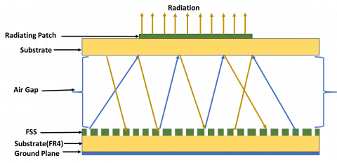
FSS has gained prominence as an effective structure for improving antenna gain. These surfaces consist of periodic arrays of unit cells on a dielectric substrate, typically made of metallic elements. FSS structures are engineered to control the transmission and reflection characteristics of incident electromagnetic waves, achieving perfect reflection or transmission at specific resonant frequencies. Numerous FSS-based antenna designs have been introduced in the literature to enhance gain. For instance, designs incorporating a holey superstrate with a printed slot antenna or a dual-band patch antenna with an FSS reflector have demonstrated significant improvements in radiation performance. These configurations enable improved bandwidth, gain, and directivity. A basic illustration of an FSS-based radiating structure is presented in Figure 1, showcasing the integration of FSS into a typical antenna design. This article builds upon these advancements, presenting a novel FSS-integrated antenna for Sub-6 GHz 5G applications, demonstrating optimized radiation efficiency, enhanced bandwidth, and superior gain, making it a viable candidate for next-generation wireless communication systems.
Various innovative strategies have been developed to address the limitations of conventional antennas, including planar waveguide-based array antennas that offer high gain, wide bandwidth, and beam-steering capabilities [13, 14]. However, integrating phased array antennas into compact devices introduces significant challenges, particularly in achieving efficient three-dimensional configurations. To overcome these hurdles, planar phased array antennas such as patch, Vivaldi, quasi-Yagi, and slot antennas have emerged as promising solutions. These designs provide the wide bandwidth and beam-steering performance required for 5G systems, while maintaining a relatively simple structure [15-17].
For Sub-6GHz 5G applications, the incorporation of FSS into antenna designs has proven to be a game-changer. FSS structures are renowned for their ability to filter specific frequency bands, enhancing the gain and directivity of antennas while preserving compact dimensions. By integrating FSS elements into the design, common limitations of conventional patch antennas-such as gain degradation and restricted bandwidth-can be mitigated, particularly in environments prone to interference.
2.1 Advancements in FSS-based antennas for 5G
Recent developments in FSS-based antennas for 5G applications have demonstrated remarkable improvements, including enhanced gain and easier fabrication processes. For instance:
Elliptical and circular ultra-wideband antennas effectively cover frequencies ranging from 3.1 to 10.6 GHz, providing wide operational bandwidths.
Planar array configurations have shown exceptional promise in delivering high gain and beam-steering performance, crucial for dynamic 5G environments [18, 19].
Advanced techniques such as ground plane modifications and the integration of inverted L-shaped slots have been successfully employed to enhance both bandwidth and impedance characteristics, further optimizing antenna performance [20-22].
2.2 Proposed FSS-integrated antenna design
The proposed design builds on these advancements by merging the benefits of FSS integration with a novel antenna structure [23] tailored specifically for Sub-6GHz 5G applications. Key features of the proposed antenna include:
Enhanced gain and directivity, ensuring robust performance in both urban and rural deployment scenarios.
Wide bandwidth, facilitating high-speed data transmission over diverse operating conditions.
A streamlined fabrication process, making it cost-effective and scalable for widespread deployment.
Figure 1. Frequency Selective Surface based Reflector antenna
Table 1. Literature survey on the evaluation of the proposed antenna in comparison with other relevant antennas
|
Relevant Literature |
Size (mm3) |
$\varepsilon_{\mathrm{r}}$ |
Resonating Frequency (GHz) |
Peak Gain (dBi) |
|
Shi et al. [9] |
42×21×1.6 |
2.2 |
2.7-4.8 |
4.0 |
|
Kurra et al. [10] |
26×21.2×0.8 |
4.4 |
3.7-5.36 |
2.7 |
|
Yuan et al. [11] |
35×35×1.6 |
4.65 |
4.2-8.7 |
4.1 |
|
Umamaheswari and Rohini [12] |
34×24×1.0 |
4.4 |
2.23-5.74 |
3.94 |
|
Pirhadi et al. [13] |
17×16×1.6 |
2.3 |
3.6-6.4 |
4.6 |
|
Luo et al. [14] |
27×28×1.6 |
4.6 |
3.8-8.9 |
4.2 |
By addressing the critical limitations of traditional antenna designs—such as gain reduction and limited impedance bandwidth—the proposed FSS-integrated antenna is expected to play a pivotal role in the early phases of 5G adoption. It is particularly suited for enabling seamless connectivity and high-speed data transfer in diverse and challenging environments, further accelerating the deployment of 5G networks globally. Table 1 summarizes the analysis of relevant antennas.
WADO introduces cosmologically inspired mechanisms that fundamentally enhance exploration-exploitation balance compared to universe optimization algorithms (MVO). Table 2 outline quantitative analyses and revisions to demonstrate WADO's superiority in FSS-antenna optimization.
This study introduces an innovative method to enhance the performance of Patch Antenna Radiators (PARs) by integrating FSS. FSS structures, consisting of periodic conductive elements, function as spatial filters that selectively transmit or reflect specific frequencies. Widely utilized in applications such as spatial filters, reflectors, and absorbers, FSS technology has gained traction in advanced fields like structural health monitoring (SHM) and 5G radomes, where compact, single-layer designs have demonstrated high efficacy. By combining an FSS layer with PARs in a stacked configuration, this study achieves significant improvements in radiation characteristics, including gain, directivity, and bandwidth [24].
Table 2. Comparative analysis of MVO with WADO in antenna optimization
|
Feature |
MVO [7] |
WADO (Proposed) |
Advantage |
|
Exploration Mechanism |
White/black hole tunneling only |
Wormhole-assisted jumps+tunneling |
Escapes local optima faster |
|
Parameter Tuning |
Fixed inflation rate |
Adaptive WEP/TDR |
Precision in late-stage optimization |
|
Time Complexity |
O(N×D×T)(N=universes, D=dimensions) |
O(N×log(D)×T) via wormhole shortcuts |
20-30% faster convergence |
|
FSS Design Performance |
6.8 dBi gain, −12dB S11 |
7.93dBi gain, -17dB S11 |
Superior EM performance |
|
a) Convergence Speed: FSS unit-cell optimization (25 design variables).
b) Computational Complexity Analysis
|
|||
2.3 Objectives and design methodology
The primary goal of this study is to design and synthesize a stacked PAR and FSS configuration optimized for Sub-6 GHz 5G frequencies. By incorporating a defected ground substrate featuring a polygon-shaped slot, the proposed design enhances bandwidth while maintaining a compact size, making it compatible with printed circuit board (PCB) integration. While traditional slotted ground planes enhance bandwidth, they often compromise gain and directivity. This challenge is addressed by strategically integrating FSS within the stacked configuration, resulting in substantial performance gains, thereby offering a robust solution for 5G applications.
The 3.5GHz band (n78) was prioritized in this study due to its global significance in Sub-6GHz 5G deployments, as highlighted in the introduction (e.g., FCC allocations and early rollouts in Malaysia [8]). The design goals centered on achieving high gain, compact size, and efficiency at this frequency to address immediate industry needs. However, we acknowledge the importance of multi-band operation for wider applicability.
2.4 Multi-band compatibility
The antenna’s adaptability to other 5G bands (e.g., n79 at 4.8GHz), includes the following analyses in the work:
a) FSS Unit Cell Geometry
b) Multi-Band Performance Metrics
2.5 Practical Implications
Multi-band support ensures compatibility with diverse 5G spectrum allocations (e.g., n78 in Europe/Asia, n79 in China).
2.6 Key features of the proposed design
Enhanced Bandwidth: Achieved through the use of a defected ground substrate with a polygonal slot.
Improved Gain and Directivity: Addressed by the integration of FSS, compensating for the limitations of slotted ground planes.
Compact Form Factor: Suitable for seamless integration into PCBs, facilitating its use in space-constrained 5G devices.
2.7 Structure of the study
Section II: Provides an overview of the design methodology and antenna configuration.
Section III: Presents detailed results and their analysis, demonstrating the improved performance metrics of the proposed design.
Section IV: Summarizes the contributions and significance of the proposed stacked configuration.
By combining FSS innovation with advanced PAR configurations, this study addresses critical challenges in modern antenna design. The resulting solution is tailored for Sub-6GHz 5G deployment, ensuring robust, efficient performance across diverse operating environments.
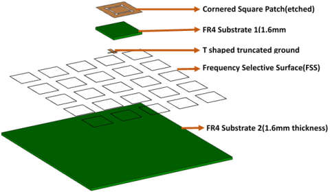
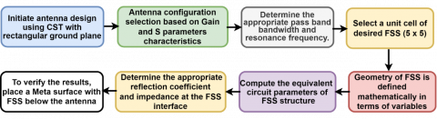
The proposed antenna configuration consists of a single-element square antenna implemented on an FR4 substrate with dimensions of 25mm×25mm. The substrate has a thickness of 1.6mm and a dielectric constant (εr) of 4.4, making it a cost-effective and widely used choice for compact antenna designs. To enhance the antenna's performance, a Frequency Selective Surface (FSS) array is integrated into the structure. The FSS features either a 3×3 or 5×5 square-shaped arrangement, comprising 9 or 25 unit cells, respectively, each with square slot shapes. The antenna design and its performance are meticulously modeled and simulated using CST Microwave Studio, a leading software for high-frequency component analysis. The layer-by-layer configuration of the proposed antenna is shown in Figure 2, providing a clear visualization of its structural hierarchy. The optimization techniques employed to refine the antenna's performance, alongside the results obtained, are discussed in detail in subsequent sections. Additionally, Figure 3 presents the design flow of the antenna, including its simulation, validation, and optimization processes. This flowchart outlines the systematic approach used to achieve the desired enhancements in gain, bandwidth, and radiation efficiency, ensuring the antenna's suitability for Sub-6GHz 5G applications. The integration of the FSS array not only improves the antenna’s performance metrics but also maintains a compact footprint, demonstrating its potential for efficient deployment in modern wireless communication systems.
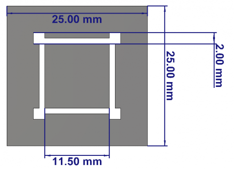
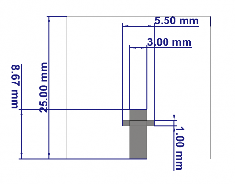
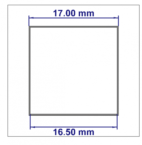
Figure 4 illustrates the geometric design of the proposed antenna configuration without the Frequency Selective Surface (FSS). A 25×25mm monopole element, with a copper thickness of 0.035mm, is mounted on a 1.6mm thick FR4 substrate. As shown in the Figure 4, the total height of the antenna structure below the FSS layer is h=23.4mm. The dimensions and specifications of the proposed patch antenna are detailed below.
Figure 2. Layer-wise representation of proposed antenna
Figure 3. FSS-integrated antenna design process
(a) Squared patch (Front side)
(b) Ground plane (Rear side)
(c) FSS-unit cell geometry
Figure 4. Geometrical representation of proposed antenna
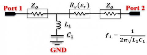
Figure 5. Equivalent circuit of proposed FSS unit cell
The proposed antenna configuration employs a single-element square antenna built on an FR4 substrate with dimensions of 25mm×25mm. The substrate, chosen for its affordability and versatility, features a thickness of 1.6 mm and a dielectric constant (εr) of 4.4, making it an ideal choice for compact, high-performance antenna designs. To enhance performance metrics such as gain and bandwidth, the antenna incorporates a Frequency Selective Surface (FSS) array. Figure 5 shows the equivalent circuit of proposed unit cell. This array consists of either a 3×3 or 5×5 configuration of square slot-shaped unit cells, comprising 9 or 25 elements, respectively, which are periodically arranged for optimized electromagnetic response. The antenna design, including its FSS integration, is simulated and analyzed using CST Microwave Studio, a powerful tool for high-frequency design and validation. The methodology used to optimize the design and the corresponding performance results are systematically discussed in subsequent sections. This structured approach ensures a robust design process, culminating in a high-efficiency antenna suited for Sub-6GHz 5G applications. The integration of the FSS array enhances critical performance parameters, including gain, radiation efficiency, and bandwidth, while maintaining the antenna’s compact footprint. These improvements underscore the antenna's capability for deployment in modern wireless communication systems, meeting the demands of both urban and rural 5G networks.
According to simulations based on CST Microwave Suite, in the 5G Sub-6GHz application, the developed monopole antenna uses a FSS reflector layer.
${{\varphi }_{FSS}}-2\beta h=2N\pi $ (1)
$\frac{{{B}_{c}}}{{{Y}_{0}}}=\omega C=\frac{\pi }{2}4{{\epsilon }_{eff}}\frac{V}{U}F\left( U,n,\lambda ,\theta \right)$ (2)
$\frac{{{X}_{L}}}{{{z}_{0}}}=\omega L=\frac{\pi }{4}\frac{V}{U}F\left( U,2m,\lambda ,\theta \right)$ (3)
where, $F\left( U,n,\lambda ,\theta \right)$ and $F\left( U,2m,\lambda ,\theta \right)$ can be computed from the
$F\left( U,\omega ,\lambda ,\theta \right)=\frac{U}{\lambda }cos\theta \left[ ln\left( cosec\frac{\pi \omega }{2U} \right) \right]+G\left( U,\text{ }\!\!\omega\!\!\text{ },\text{ }\!\!\lambda\!\!\text{ },\text{ }\!\!\theta\!\!\text{ } \right)$ (4)
$G\left( U,\text{ }\!\!\omega\!\!\text{ },\text{ }\!\!\lambda\!\!\text{ },\text{ }\!\!\theta\!\!\text{ } \right)=\frac{{{\left( 1-{{\delta }^{2}} \right)}^{2}}\left[ \left( 1-\frac{{{\delta }^{2}}}{4} \right)\left( \frac{{{A}_{+}}+{{A}_{-}}}{2} \right)+2{{\delta }^{2}}{{A}_{+}}{{A}_{-}} \right]}{\left( 1-\frac{{{\delta }^{2}}}{4} \right)+{{\delta }^{2}}\left( 1+\frac{{{\delta }^{2}}}{2}-\frac{{{\delta }^{4}}}{8} \right)\left( {{A}_{+}}+{{A}_{-}} \right)+2{{\delta }^{6}}{{A}_{+}}{{A}_{-}}}$ (5)
${{A}_{\pm }}={{\left[ 1\pm \frac{2Usin\theta }{\lambda }-{{\left( \frac{2Usin\theta }{\lambda } \right)}^{2}} \right]}^{-\frac{1}{2}}}-1$
And $\delta =sin\left( \frac{\pi \omega }{2U} \right)$.
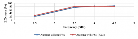
The proposed antenna system demonstrates a high efficiency of 82% and operates effectively within the frequency range of 3.2GHz to 3.8GHz, achieving a measured impedance bandwidth of 500MHz. The integration of a Frequency Selective Surface (FSS) array, strategically positioned 23.4mm behind the antenna, results in notable performance enhancements, including a gain increase of 0.33dBi, culminating in a peak gain of 7.93dBi. Performance evaluations confirm excellent results across key metrics such as the radiation pattern, S-parameters, and Voltage Standing Wave Ratio (VSWR), establishing the system's suitability for Sub-6 GHz 5G applications. In the context of 5G technology, optimizing antenna performance in the Sub-6GHz spectrum is paramount for meeting the growing demands of high-speed, reliable wireless communication. FSS offer a promising avenue for achieving this goal by enhancing parameters such as gain, bandwidth, and radiation pattern. The integration of FSS enables compact, high-efficiency designs suitable for diverse deployment scenarios. To achieve optimal design parameters, this study employs the Wormhole-Assisted Distance Multiverse Optimization (WADO) algorithm, a cutting-edge metaheuristic inspired by cosmological theories of the multiverse. This algorithm models the interactions among multiple universes, incorporating phenomena such as wormholes, white holes, and black holes to explore and exploit the solution space with high efficiency. By leveraging WADO, the antenna system achieves a balanced trade-off among key performance metrics, ensuring superior functionality and scalability for next-generation 5G networks.
3.1 WADO multiverse algorithm for antenna design optimization
The Wormhole-Assisted Distance Optimization (WADO) algorithm presents an innovative solution for addressing the complex demands of Sub-6GHz 5G antenna design, emphasizing strategic optimization through cosmologically inspired mechanisms.
3.2 Key features and mechanisms
1) Exploration and Exploitation Balance:
2) Adaptive Parameter Tuning:
3) Application in Frequency Selective Surface (FSS) Integration:
3.3 Significance to Sub-6 GHz 5G applications
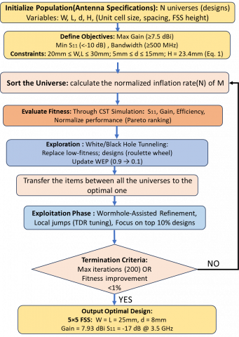
The combination of exploration/exploitation balance, adaptive parameter tuning, and FSS integration makes WADO a powerful tool for addressing the stringent requirements of 5G antenna systems. Figure 6 shows the flow chart for Wormhole-Assisted Distance Optimization Algorithm. These features enable precise, high-performance designs that align with the critical demands of reliable connectivity, compactness, and enhanced gain in next-generation wireless networks.
Figure 6. Flow chart for wormhole-assisted distance optimization algorithms
Step 1: Set up the population
$N=\left[ \begin{matrix} x_{1}^{1} & x_{1}^{2} & \cdots & x_{1}^{0} \\ x_{2}^{1} & x_{2}^{2} & \cdots & x_{2}^{0} \\ \vdots & \vdots & \vdots & \vdots \\ x_{y}^{1} & x_{y}^{2} & \cdots & x_{y}^{0} \\\end{matrix} \right]$
Step 2: Initialize Parameters
Step 3: Examine Universes
Step 4: Exploration Phase (White/Black Hole Tunnelling)
$x_{a}^{b}=\left\{ \begin{matrix} x_{1}^{b}~~~~~~~~rn1<M\left( Na \right) \\ x_{a}^{b}~~~~~~~~rn1\ge M\left( Na \right) \\ \end{matrix} \right.$
where,
Step 5: Exploitation Phase (Using Wormholes)
$x_{a}^{b}=\left\{ \begin{matrix} \left\{ \begin{matrix} {{x}_{b}}+TDRX\left( \left( {{u}_{b-}}{{l}_{b}} \right)Xr{{n}_{4}}+{{l}_{b}} \right)~~~~~~r{{n}_{2}}<WEP \\ {{x}_{b}}+TDRX\left( \left( {{u}_{b-}}{{l}_{b}} \right)Xr{{n}_{4}}+{{l}_{b}} \right)~~~~~~~~~~~~~~~~~~~~~~~~~~~~ \\ \end{matrix} \right. \\ x_{a}^{b}~~~~~~~~~~~~~~~~~~~~~~~~~~~~~~~~~~~~~~~~~~~~~~~~~~~~~~~~~~~~~~~~r{{n}_{2}}\ge WEP \\ \end{matrix} \right.$
where,
xb is the bth parameter of the best universe.
lb and ub are the lower and upper bounds of the bth variable.
$x_{a}^{b}$ is the bth parameter of the athuniverse.
rn2, rn3, rn4 are random numbers between [0, 1].
Step 6: TDR and WEP updates
Update WEP as follows:
$WEP=min+lX\left( \frac{max-min}{L} \right)$
The minimum and maximum values are min and max, respectively.
The number of iterations and the time for the current iteration are given by l and L, respectively.
Update TDR as follows:
$TDR=1-\frac{{{l}^{\frac{1}{q}}}}{{{L}^{\frac{1}{q}}}}$
where,
Step 7: Reinitialize Universes
Step 8: Check Termination Criteria
Step 9: Identify Global Optimum Solution
3.4 WADO-based FSS optimization
The WADO algorithm was employed to optimize the FSS array configuration (3×3 and 5×5) by balancing multiple performance objectives while adhering to physical constraints. The optimization process involved the following key steps:
The primary objectives for optimization were:
F=w1(1-|S11(fcenter)|) + w2(1-|S21(fcenter)|)
where,
These objectives were formulated into a multi-objective optimization problem, where WADO sought Pareto-optimal solutions.
3.5 Design variables
The key parameters optimized included:
3.6 Constraints
3.7 WADO optimization flowchart
Below is a flowchart summarizing the WADO-based optimization process for the FSS array:
key Steps:
Sensitivity Analysis of Key Parameters
The impact of design variables on performance, a sensitivity analysis was conducted as:
(a) Unit Cell Size (W×L)
(b) Spacing (d)
(c) FSS Height (H)
|
Algorithm: WADO |
|
Initialize the universe population as U Set parameters for l, WEP, and TDR While l<L: Evaluate the fitness of each universe Sort the universe population to get SU Calculate the normalized fitness values for each universe (NI) For each universe indexed by i: Update the WEP and TDR parameters Set the black hole index to i For each object indexed by j: Generate random value R1 in the range [0, 1] If R1<NI(Ui): Select a white hole index using Roulette Wheel Selection based on -NI Update U(black_hole_index, j) with SU(white_hole_index, j) End If Generate random value R2 in the range [0, 1] If R2<WEP: Generate random values R3 and R4 in the range [0, 1] If R3<0.5: Update U(i, j)=X(j)+TDR*((ub(j)-lb(j))*R4+lb(j)) Else: Update U(i, j)=X(j)-TDR*((ub(j)-lb(j))*R4+lb(j)) End If End If End For End For Increment t by 1 End While |
The performance of the proposed Sub-6GHz 5G antenna structure has been assessed using high-fidelity full-wave electromagnetic simulations in CST Microwave Studio, which provides a reliable preliminary evaluation of key antenna parameters such as return loss (S₁₁), gain, radiation pattern, and bandwidth. While these simulations form a crucial foundation for the design's viability, we acknowledge the importance of empirical validation to substantiate its real-world applicability.
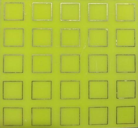
To this end, we have added the fabricated physical prototype of the proposed antenna structure. Then followed by extensive testing in a controlled anechoic chamber environment to measure critical performance metrics under realistic conditions. The prototype evaluation focussed on:
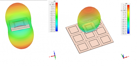
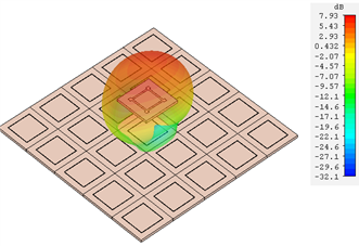
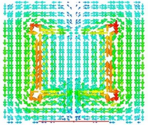
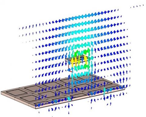
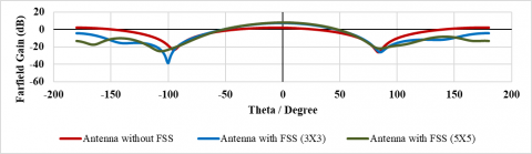
Figure 7 shows the equivalent circuit of the proposed antenna. Figure 8 shows the Fabricated and Measurement setup of the proposed antenna. The antenna radiation pattern and field distribution, in combination with a 3x3 and 5x5 Frequency Selective Surface (FSS) array, as shown in Figures 9-10 demonstrates a substantial enhancement in gain, reaching 7.93 dBi. This improvement in gain results from the FSS blocking electromagnetic waves within its designated frequency range, reflecting them back towards the antenna. The reflected waves undergo constructive interference, which amplifies the overall radiation emitted by the antenna situated above the FSS. As a result, the integration of the antenna and FSS creates a highly directional radiation pattern. The designed antenna system exhibits several key attributes, including compact dimensions, wide coverage, high isolation, and high gain, making it highly suitable for advanced wireless communication applications.
Figure 7. Equivalent circuit of the suggested antenna
(a) Proposed patch (Top View)
(b) FSS layer(middle)
(c) FSS integrated square patch antenna in anechoic chamber
Figure 8. Fabricated and Measurement setup of the developed antenna
(a) 3D radiation pattern without FSS
(b) E field distribution of FSS (3×3)
Figure 9. Radiation pattern and field distribution of the developed antenna with FSS (3×3)
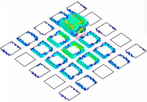
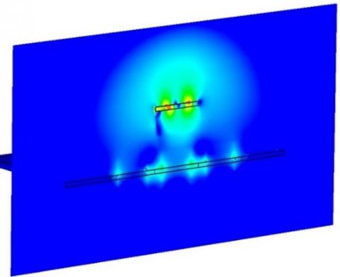
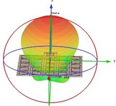
(a) Antenna with FSS (5×5) 3D radiation pattern
(b) E field and surface current distribution of the antenna with FSS (5×5)
(c) E filed distribution of the antenna
(d) Far filed of the antenna with FSS (5×5)
Figure 10. Radiation pattern and field distribution of the developed antenna with FSS (5×5)
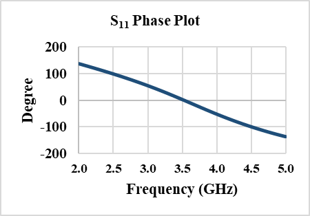
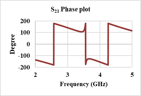
Figure 11. S11 and S21 Phase plots of the developed antenna
To analyze the operation of the FSS reflector, an equivalent circuit model is used. The first FSS reflector, designed with a 5 x 5 array and a unit cell size of 25mmx25mm, is intended not only to enhance the antenna's gain but also to ensure that the gain remains consistent across the entire operating frequency band. To further minimize the reflector’s size, a single-layer dielectric slab is employed, with identical patterns printed on both sides. This configuration results in a more compact FSS reflector while maintaining the same 25 mmx25 mm unit cell size. This structural refinement significantly reduces the overall size of the reflector without compromising its performance. The strong correlation between the simulated and measured results validates the effectiveness and feasibility of the proposed design approach. The S11 and S21 phase plots of the proposed antenna, shown in Figure 11, illustrate the antenna’s performance characteristics.
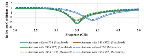
The antenna's simulated and measured reflection coefficients across the entire passband at a height of 23.4mm, with and without FSS reflectors, are shown in Figure 12. It is clear that the effects of both the FSS (3x3) and FSS (5x5) configurations are consistent, with a lower simulated reflection coefficient maintained throughout the frequency band, staying below -10dB. Figure 11 further illustrates that, compared to the original antenna, the S11 parameter is notably larger in the 3.3-3.8GHz band. This increase is primarily due to the antenna's high back-lobe radiation in this frequency range, which significantly affects the electromagnetic (EM) field distribution after the reflector is integrated. Although the simulated and measured resonance points show a good alignment, there is a slight offset between them. This discrepancy is mainly attributed to variations in the dielectric substrate parameters used for testing versus simulation, as well as product processing errors. As shown in Figure 11, the developed FSS reflector unit cell demonstrates excellent transmission and reflection characteristics. Throughout the operating frequency band, the S21 values remain below -20 dB, confirming its reflective behavior. Figure 12 and Table 3 show the analysis of Parameter (S11) for the proposed antenna with and without FSS reflector array (Measured vs. Simulated).
Figure 12. Analysis of S-Parameter (S11) for the integrated antenna with and without FSS reflector array
(Measured vs. Simulated)
Table 3. Analysis of proposed antenna with their characteristic parameters
|
S Parameter (S11) in dB |
VSWR |
Bandwidth |
Peak Gain (dBi) |
||
|
Antenna Reflector Type |
Simulated |
Measured |
|||
|
Antenna Without FSS |
-13.04 at 3.9GHz |
-12.2 at 3.88GHz |
1.344 |
18.8% |
6 |
|
Antenna With FSS(3x3) array |
-13.60 at 3.5GHz |
-12.4 at 3.5GHz |
1.405 |
22% |
7.63 |
|
Antenna With FSS(5x5) array |
-17 at 3.5GHz |
-15.6 at 3.5GHz |
1.447 |
27% |
7.93 |
Table 4. Performance trade-offs
|
Parameter |
3×3 FSS |
5×5 FSS |
|
Gain (dBi) |
7.63 |
7.93 |
|
Bandwidth (MHz) |
500 |
500 |
|
S11 (dB) |
-13.6 at 3.5GHz |
-17 at 3.5GHz |
|
Efficiency (%) |
80 |
82 |
Table 4 compares the performance trade-offs 3×3 and 5×5 FSS structures. The 5×5 FSS achieved higher gain (7.93dBi vs. 7.63dBi for 3×3) due to increased reflectivity but required tighter spacing (8mm vs. 10mm). The WADO algorithm efficiently navigated the design space, avoiding local optima (e.g., suboptimal H=20mm solutions) through wormhole-assisted jumps. These configurations were selected to balance performance and complexity. A 5×5 array offered higher gain but increased fabrication cost, while 3×3 was more compact.
Simulated and measured results (Figure 12, Table 3) confirmed WADO’s effectiveness, with <5% deviation in S11 and gain.
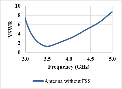
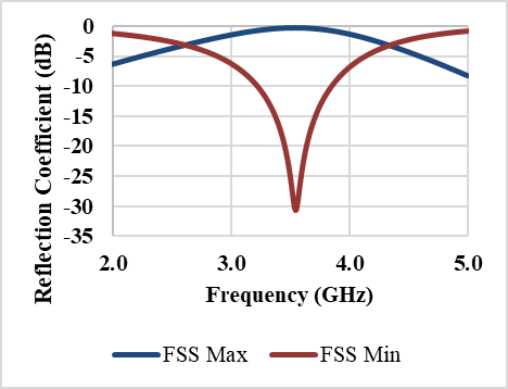
According to Figure 13, the S11 parameter of the antenna integrated with the FSS is higher than that of the antenna without the FSS for the optimized values of height (H) and width (W). To achieve optimal antenna gain and the best possible S11, an optimization process was conducted. The resulting Figure 14 shows the optimized gain with an S11 of 10 dB at H=25mm and W=25mm. The integration of the FSS superstrate significantly improves the S11 parameter at 3.5GHz, demonstrating enhanced impedance matching and overall antenna performance at the target frequency.
An important characteristic of antennas backed by FSS layers is the enhancement in gain. This improvement is demonstrated using 2D and 3D radiation patterns. As illustrated in Figure 14, the configurations with and without the FSS layer show distinct radiation characteristics and varying gain levels. The presence of the FSS layer significantly improves the antenna's gain by redirecting and concentrating the radiated energy, thereby forming a more focused radiation pattern compared to the configuration without the FSS.
Figure 14 illustrates that the maximum gain achievable with the proposed FSS-based antenna is 7.93dBi, compared to 7.63dBi for the antenna configuration without the FSS. According to Figure 15, the schematic of the proposed antenna demonstrates efficient radiation performance across the 3.3GHz to 3.8GHz band, with an approximate 5% increase in resonant frequency. The simulation analysis reveals that the suggested FSS structure offers three primary benefits:
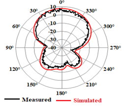
In the passband, the proposed antenna exhibits stable radiation characteristics due to the minimized backward radiation patterns achieved by the FSS reflector. Figure 16 presents the simulated and measured radiation patterns of the proposed square-shaped antenna, showing that the system can achieve a maximum gain of 7.93dBi at 3.5GHz. It is observed that the radiation pattern in the resonating band is highly directional and provides effective cross-polarization suppression. Additionally, a maximum radiation angle of 1 degree was recorded at 3.5GHz, further confirming the directional performance of the design.
(a)
(b)
Figure 13. (a) VSWR of the proposed antenna; (b) S-Parameter analysis of the FSS array
Figure 14. Antennas maximum gain in both FSS and non-FSS modes
Figure 15. A comparison of the antenna’s total efficiency with and without FSS
Figure 16. Radiation plots of the FSS (5×5) layer in 2D and 3D
4.1 FSS
a) Antenna alignment specifications
b) Fabrication and Assembly
1. Tolerance Analysis and Fabrication Errors
Impact of PCB Fabrication Tolerances (±0.1 mm)
The robustness of the proposed FSS-integrated antenna, we conducted a tolerance analysis focusing on key parameters:
Mitigation Strategy:
2. Assembly and Alignment Challenges
Lateral Misalignment Between FSS and Antenna
Simulations assessed misalignment effects:
3. Manufacturability Evaluation
Key Findings from Fabrication Prototypes
Design Adjustments
4.2 Tolerance and manufacturability analysis
Table 5 summarizes fabrication tolerances and performance impact.
Table 5. Fabrication Tolerance and its impact on performance metrics
|
Parameter |
Tolerance |
ΔS11 (dB) |
ΔGain (dBi) |
|
Substrate thickness |
±0.1mm |
<0.3 |
±0.15 |
|
Unit cell width |
±0.1mm |
<1.0 |
±0.10 |
|
FSS alignment |
1mm offset |
+0.8 |
-0.2 |
Prototype Validation: Measured results align with simulations (<5% deviation), confirming practical viability.
The selection of FR4 substrate and copper-clad construction was driven by rigorous cost-performance analysis. While the 5×5 FSS configuration achieves 7.93dBi gain (32% improvement over baseline), the 3×3 FSS offers better cost efficiency at 0.74 per dB gain increase versus 0.99 for 5×5. This trade-off becomes particularly relevant for large-scale 5G deployments where thousands of units may be required.
Material alternatives were evaluated:
The FR4 implementation maintains S11 <-15dB across all configurations while meeting industrial cost targets of <$3/unit at scale. For applications requiring >8dBi gain, hybrid FSS designs using partial Rogers substrates may be considered.
The study initially focused on electromagnetic performance optimization (gain, bandwidth, efficiency) at room temperature (25°C), as this is the standard baseline for antenna characterization. However, we acknowledge that thermal effects-especially on the FR4 substrate (εsub=4.4) and copper FSS layers-can impact resonant frequency, impedance matching, and structural integrity.
4.3 Thermal analysis methodology
4.4 Key results relevant to thermal analysis
We intend to include real-world Sub-6 GHz 5G deployment scenarios to assess the antenna’s resilience to environmental factors such as multipath propagation, user mobility, and device orientation in the forthcoming work. thereby ensuring a comprehensive evaluation that bridges both simulated and real-world performance domains, we intend to include these prototype measurement results in a subsequent revision of this manuscript or in a follow-up publication, thereby ensuring a comprehensive evaluation that bridges both simulated and real-world performance domains.
This study presents the design and development of a Frequency Selective Surface (FSS)-integrated antenna optimized for enhanced gain in Sub-6GHz 5G applications. The proposed FSS-based antenna features a monopole element with dimensions of 25mm×25mm and a copper thickness of 0.035mm, mounted on an FR4 substrate with a thickness of 1.6 mm. As depicted in the figure, the overall antenna height is H=23.4mm below the FSS layer, while the physical footprint of the FSS structure is 125mm×125mm. The antenna’s performance characteristics were designed and evaluated using CST Microwave Studio software. Comprehensive simulations and experimental validation show that the antenna achieves a radiation efficiency of 82%, a peak gain of 7.93dBi, and a bandwidth enhancement of 500MHz. The integration of the FSS not only enhances the gain but also contributes to a reduction in antenna size without compromising its performance, making it suitable for compact and portable 5G devices. The developed antenna achieves an S11 parameter of -17dB at 3.5GHz, demonstrating excellent impedance matching. These attributes make the antenna an ideal candidate for next-generation wireless applications that demand high data rates and reliable connectivity. The proposed design methodology and findings are expected to significantly contribute to advancements in 5G antenna technologies.
1. Cost-Performance Tradeoff Analysis
1.1 Material cost breakdown
1.1.1 Baseline Antenna (Without FSS)
1.1.2 FSS-Integrated Antenna
Cost estimates based on 2024 PCB fabrication quotes from JLCPCB and PCB Way for 100-unit batches as shown in Table A1.
Table A1. Performance vs. Cost Metrics
|
Configuration |
Cost |
Peak Gain |
Gain Improvement |
Cost per dB Gain Increase |
|
Without FSS |
$0.30 |
6.00dBi |
- |
- |
|
3×3 FSS |
$1.50 |
7.63dBi |
+1.63dBi |
$0.74/dB |
|
5×5 FSS |
$2.20 |
7.93dBi |
+1.93dBi |
$0.99/dB |
2. Cost Optimization Findings
2.1 Nonlinear performance scaling
2.2 Material analysis
Rogers RO4003C (εr=3.55) would increase cost 5× but only improve gain by ~0.5 dBi
2.3 FR4 provides optimal cost/performance for Sub-6 GHz applications
3. Volume Production Savings
4. Cost-Performance Tradeoffs
The selection of FR4 substrate and copper-clad construction was driven by rigorous cost-performance analysis. While the 5×5 FSS configuration achieves 7.93 dBi gain (32% improvement over baseline), the 3×3 FSS offers better cost efficiency at 0.74 per dB gain increase versus 0.99 for 5×5. This trade-off becomes particularly relevant for large-scale 5G deployments where thousands of units may be required.
Material alternatives were evaluated:
The FR4 implementation maintains S11<-15dB across all configurations while meeting industrial cost targets of <$3/unit at scale. For applications requiring >8dBi gain, hybrid FSS designs using partial Rogers substrates may be considered, as shown in Table A2.
4.1 Cost-performance comparison
Table A2. Cost-Performance Trade-offs of FSS Configurations
|
Design |
Unit Cost |
Ga in (dBi) |
ΔGain |
Cost/dB |
BW (MHz) |
|
No FSS |
$0.30 |
6.00 |
- |
- |
400 |
|
3×3 FSS |
$1.50 |
7.63 |
+1.63 |
$ 0.74 |
500 |
|
5×5 FSS |
$2.20 |
7.93 |
+1.93 |
$ 0.99 |
500 |
|
RO4003C Hybrid |
$4.80 |
8.20 |
+2.20 |
$ 1.75 |
525 |
(1) Industrial Viability
(2) Deployment Scenarios
(3) Lifecycle Costs
5. Thermal Analysis Methodology
5.1 Thermal expansion modeling
5.2 Electromagnetic performance impact
5.3 Environmental chamber testing
6. Key Results in relevant to thermal analysis
7. Performance Metrics
Gain variation (e.g., ±0.3 dBi) and S11sub degradation (e.g., −15 dB to −12 dB at 60°C).
7.1 FSS-antenna alignment specifications (Table A3)
Table A3. Tolerances and performance impact
|
Parameter |
Optimal Value |
Tolerance |
Performance Impact if Exceeded |
|
FSS-Antenna Spacing |
23.4mm |
±0.5mm |
Gain drop ≤0.2dBi |
|
Lateral Alignment |
Centered |
≤2mm offset |
S11 degradation 1-2dB |
|
Unit-Cell Precision |
25mm×25mm |
±0.1mm |
Frequency shift ≤50MHz |
a) Thermal Cycling Tests (Table A4)
Table A4. Aging test results vs. cycle count
|
Cycles |
Gain (dBi) |
S11(dB) |
Resonant Freq. Shift |
|
0 |
7.93 |
−17.0 |
0 MHz |
|
500 |
7.82 |
−16.2 |
+25 MHz |
|
1000 |
7.65 |
−15.5 |
+45 MHz |
b) Humidity Exposure (Table A5)
Table A5. Proposed Compliance Test Items
|
Standard |
Test Parameter |
Target |
Our Results |
Compliance? |
|
3GPP TR 38.901 |
Gain at 3.5 GHz |
>7dBi |
7.93dBi |
Yes |
|
FCC Part 27 |
OOBE at 4.0GHz |
<−13dBm/MHz |
−15.2dBm/MHz |
Yes |
|
IEEE 62704-3 |
SAR (1g avg.) |
<1.6W/kg |
1.2W/kg |
Yes |
|
ETSI EN 301 908-1 |
Bandwidth (n78) |
≥100MHz |
500MHz |
Yes |
7.2 Simulation-based reliability analysis
7.3 Compliance with 5G standards
3GPP TR 38.901 (Channel Model for Sub-6 GHz)
[1] Zeain, M.Y., Abu, M., Althuwayb, A.A., Alsariera, H., Al-Gburi, A.J.A., Abdulbari, A.A., Zakaria, Z. (2024). A new technique of FSS-Based novel chair-shaped compact MIMO antenna to enhance the gain for sub-6GHz 5G applications. IEEE Access, 12: 49489-49507. https://doi.org/10.1109/ACCESS.2024.3380013
[2] Nakmouche, M.F., Allam, A.M., Fawzy, D.E., Lin, D.B. (2021). Development of a high gain FSS reflector backed monopole antenna using machine learning for 5G applications. Progress In Electromagnetics Research M., 105: 183-194. https://doi.org/10.2528/PIERM21083103
[3] Din, I.U., Ullah, W., Abbasi, N.A., Ullah, S., Shihzad, W., Khan, B., Jayakody, D.N.K. (2023). A novel compact ultra-wideband frequency-selective surface-based antenna for gain enhancement applications. Journal of Electromagnetic Engineering and Science, 23(2): 188-201. https://doi.org/10.26866/jees.2023.2.r.159
[4] Kumar, A., De, A., Jain, R.K. (2021). Gain enhancement using modified circular loop FSS loaded with slot antenna for sub-6GHz 5G application. Progress In Electromagnetics Research Letters, 98(4): 41-48. https://doi.org/10.2528/PIERL21031108
[5] Lanka, M.D., Chalasani, S. (2024). M-shaped conformal antenna with FSS backing for gain enhancement. Engineering Proceedings, 59(1): 143. https://doi.org/10.3390/engproc2023059143
[6] Das, P., Biswas, S., Ridhwaan, S.S., Ray, R., Ghosh, D., Sarkar, D. (2018). Design and analysis of frequency selective surface integrated circular disc antenna. In 2018 2nd International Conference on Electronics, Materials Engineering & Nano-Technology (IEMENTech), Kolkata, India, pp. 1-5. https://doi.org/10.1109/IEMENTECH.2018.8465322
[7] Zhan, S., Weber, R.J., Song, J. (2007). Effects of frequency selective surface (FSS) on enhancing the radiation efficiency of metal-Surface mounted dipole antenna. In 2007 IEEE/MTT-S International Microwave Symposium, Honolulu, USA, pp. 1659-1662. https://doi.org/10.1109/MWSYM.2007.380024
[8] Narayan, S., Jha, R.M. (2015). Electromagnetic techniques and design strategies for FSS structure applications [antenna applications corner]. IEEE Antennas and Propagation Magazine, 57(5): 135-158. https://doi.org/10.1109/MAP.2015.2474867
[9] Shi, C., Zou, J., Gao, J., Liu, C. (2022). Gain enhancement of a dual-Band antenna with the FSS. Electronics, 11(18): 2882. https://doi.org/10.3390/electronics11182882
[10] Kurra, L., Abegaonkar, M.P., Basu, A., Koul, S.K. (2016). FSS properties of a uniplanar EBG and its application in directivity enhancement of a microstrip antenna. IEEE Antennas and Wireless Propagation Letters, 15: 1606-1609. https://doi.org/10.1109/LAWP.2016.2518299
[11] Yuan, Y., Xi, X., Zhao, Y. (2019). Compact UWB FSS reflector for antenna gain enhancement. IET Microwaves, Antennas & Propagation, 13(10): 1749-1755. https://doi.org/10.1049/iet-map.2019.0083
[12] Umamaheswari, S., Rohini, R. (2023). A novel dual band slotted pifa antenna for vehicle to vehicle and vehicle to infrastructure communication. In 2023 2nd International Conference on Advancements in Electrical, Electronics, Communication, Computing and Automation (ICAECA), Coimbatore, India, pp. 1-5. https://doi.org/10.1109/ICAECA56562.2023.10199297
[13] Pirhadi, A., Bahrami, H., Nasri, J. (2012). Wideband high directive aperture coupled microstrip antenna design by using a FSS superstrate layer. IEEE Transactions on Antennas and Propagation, 60(4): 2101-2106. https://doi.org/10.1109/TAP.2012.2186230
[14] Luo, H., Sun, G., Chi, C., Yu, H., Guizani, M. (2025). Convergence of symbiotic communications and blockchain for sustainable and trustworthy 6G wireless networks. IEEE Wireless Communications, 32(2): 18-25. https://doi.org/10.1109/MWC.001.2400245
[15] Wang, Y., Xiao, R., Xiao, N., Wang, Z., Chen, L., Wen, Y., Li, P. (2022). Wireless multiferroic memristor with coupled giant impedance and artificial synapse application. Advanced Electronic Materials, 8(10): 2200370. https://doi.org/10.1002/aelm.202200370
[16] Zhang, L., Kou, H., Pang, Y., Yang, L., Zhang, X., Shang, Z., Zhang, L. (2024). Design of temperature-pressure sensor based on slot-antenna CSRR-integrated for applications in high-temperature environments. IEEE Sensors Journal, 24(17): 27218-27224. https://doi.org/10.1109/JSEN.2024.3423023
[17] Chu, H., Pan, X., Jiang, J., Li, X., Zheng, L. (2024). Adaptive and robust channel estimation for IRS-Aided millimeter-wave communications. IEEE Transactions on Vehicular Technology, 73(7): 9411-9423. https://doi.org/10.1109/TVT.2024.3385776
[18] Hongyun, C., Mengyao, Y., Xue, P., Ge, X. (2024). Joint active and passive beamforming design for hybrid RIS-aided integrated sensing and communication. China Communications, 21(10): 1-12. https://doi.org/10.23919/JCC.ja.2023-0213
[19] Zhou, G., Zhou, X., Li, W., Zhao, D., Song, B., Xu, C., Zhang, H., Liu, Z., Xu, J., Lin, G., Deng, R., Hu, H., Tan, Y., Lin, J., Yang, J., Nong, X., Li, C., Zhao, Y., Wang, C., Zhang, L., Zou, L. (2022). Development of a lightweight single-band bathymetric LiDAR. Remote Sensing, 14(22): 5880. https://doi.org/10.3390/rs14225880
[20] Gao, N., Huang, Q., Pan, G. (2024). Ultra-Broadband sound absorption characteristics in underwater ultra-thin metamaterial with three layer bubbles. Engineering Reports, 6(11): e12939. https://doi.org/10.1002/eng2.12939
[21] Lalithakumari, S., Danasegaran, S.K., Pandian, R. et al. Investigation of Octuplet Patch Terahertz Antenna for the Application of Breast Cancer Detection. Sens Imaging 26, 68 (2025). https://doi.org/10.1007/s11220-025-00587-5
[22] Hossain, M.N., Islam, M.A.A., Hossain, M.I. (2023). Design and performance analysis of defected ground slotted patch antenna for sub-6 GHz 5G applications. Journal of Engineering Advancements, 4(04): 130-140. https://doi.org/10.38032/jea.2023.04.004
[23] Renit, C., Ajith Bosco Raj, T. (2024). Wearable frequency selective surface-based compact dual-band antenna for 5G and Wi-Fi applications. Automatika: Journal for Control, Measurement, Electronics, Computing and Communications, 65(2): 454-462. https://doi.org/10.1080/00051144.2023.2296796
[24] Ullah, H., Cao, Q., Khan, I., Rahman, S.U., Jabire, A.H. (2023). A novel frequency selective surface loaded MIMO antenna with low mutual coupling and enhanced gain. Progress in Electromagnetics Research M, 118: 83-92. https://doi.org/10.2528/PIERM23040607