Mouloud Ayad* | Kamel Saoudi | Turki E.A. Alharbi | Mohammed S. Alzaidi | Mourad Benziane | Souhil Mouassa | Sherif S.M. Ghoneim
© 2022 IIETA. This article is published by IIETA and is licensed under the CC BY 4.0 license (http://creativecommons.org/licenses/by/4.0/).
OPEN ACCESS
A microstrip patch antenna for Global Positioning System (GPS) application is presented in this study. It has a rectangular shape with two notched slots. The notched slots are introduced to improve the adaptation between the microstrip line and the antenna. The antenna was designed and simulated by CST using FR-4 material as the substrate with relative permittivity of 4.3. The proposed microstrip antenna is designed to operate in the GPS band frequency from 1.555 GHz to 1.595 GHz. The performance analysis of the proposed antennas has been carried out in terms of return loss (dB), gain (dB), and VSWR.
microstrip patch antenna, GPS, return loss, VSWR
Telecommunications systems are very widely present in our current smart lifestyles. The Global Positioning System (GPS) is one of these systems. It is a satellite geographic positioning system used by various navigation systems. These localization systems have become essential to the tremendous demands for new services and applications in multiple civil and military domains. GPS is very widely used in several domains, such as in monitoring systems [1-6], intelligent systems [7-9], power management [10], and other applications. Moreover, GPS can provide real-time location information for an unlimited number of users. A satellite navigation system allows users equipped with a receiver to calculate and determine their position at any place on earth from the estimation of the distance which separates them from a minimum number of satellites. When we talk about GPS, we must systematically and specifically consider the equipment used to provide location. However, the GPS is not limited to this type of instrument, as it consists of three different elements called segments or sectors. The first segment of satellites is called the space segment. The second segment comprising the control station is called the control segment, and the last segment corresponding to the GPS receiver is called the user segment. In user equipment, we find the essential element of transmission. In the GPS systems, the antennas do the emission and reception of the data. These antennas are used at the reception level and are generally placed in land vehicles, aircraft, and ships to precisely locate their positions. It has advantageous characteristics (wide frequency band, security, and high speed). The antennas aim to perfect and improve several performances for all wireless communication systems [11-14]. Therefore, the antenna is a crucial element for coupling the device and the propagation medium. Hence, the design and proposition of a microstrip patch antenna for GPS application is a vital task.
Several microstrip patch antenna are presented in the literature for GPS applications [15-23].
Supriya and Rajendran [17] proposed an antenna for a GPS system based on an open-loop resonator, a split rectangular slot, and a stub at the non-radiating edge to generate three operating bands. Awais et al. [18] use four-element antenna array for the proposed antenna for a navigation satellite system. It is an assembled of 4 single patch antenna elements. Based on a circularly polarized dielectric resonator, Sharma et al. [19] present an antenna for GPS application that operates at 1.56 GHz. Lee et al. [20] proposed a patch antenna with a metallic reflector. This antenna is designed for GPS applications and operates at 1.575 GHz. The occupied volume by the antenna and the reflector is very extensive. With the addition of an artificial magnetic conductor plane, the proposed antenna [21] operates with a dual-band at 1.575 GHz for GPS and at 2.45 GHz for WLAN applications. Another antenna that operates in dual bands for GPS application is proposed by Zhong et al. [22]. The proposed antenna consists of two patches to generate two bands. Another antenna is proposed by Pourbagher et al. [23] with circular polarization. The structure of the antenna is composed of two orthogonally dipoles.
The main challenges in these proposed antennas are volume and occupied areas. Therefore, this paper aims to design, simulate, and analyze an antenna with a reduced volume destined for GPS application.
The rest of this paper is organized as follows: In section 2, the antenna design steps are presented. The results and discussion are given in Section 3. Finally, the last section provides the conclusion.
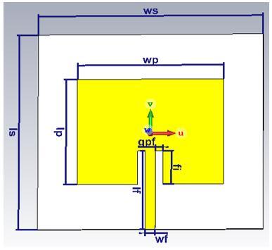
This part is devoted to studying the influence of the different parameters on the reflection coefficient S11 and the VSWR. A parametric study was conducted to obtain an effective and optimized final structure to understand the various parameters' influence. We use FR-4 material as the substrate, usually with relative permittivity equal to 4.3. The parameters to modify are the length (Lp) and the width (Wp) of the patch, the width of the microstrip line (Wf), the width (gpf), and the length (fi) of the notch, and the thickness of the substrate (hs). The proposed antenna structure and detailed configurations are illustrated in Figure 1.
Figure 1. Antenna structure
This part will present the structure and simulation results of the patch antenna of rectangular shape fed by the microstrip line, and this is for a GPS application in a frequency band of value 1.575 GHz [20-23].
The sections below present the evolution steps of the design of the proposed antenna according to the following forms: the ground plane, the substrate, and the radiating patch. For this antenna, we have chosen a power supply by microstrip line. The parametric study justifies this choice to improve the GPS frequency band of [1.555-1.595] GHz.
2.1 Influence of the (Lp) patch length
The length of the patch has a vital role in determining the resonant frequency. This part will allow us to see the variation in the size of the patch (Lp). The results obtained are represented the Table 1.
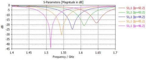
Figure 2. Influence of length (lp) by the contribution of reflection coefficient (S11)
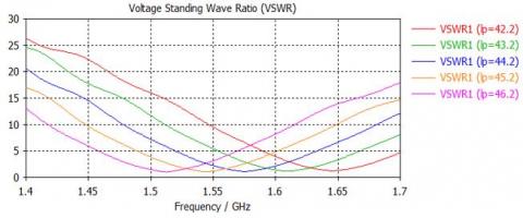
Figure 3. Influence of the length (lp) by the standing wave ratio VSWR contribution
Figure 2 and Figure 3 show the results of the influence of the length of the patch (Lp) by input reflection coefficient (S11) and the VSWR.
In Figure 3, we note that the length of the patch mainly affects the matching of the antenna. The patch size (lp) reduction leads to an increase in the resonant frequency and bandwidth. Also, from Figure 3 and Table 1, we observed that for all changes in length that we made, the VSWR remains less than 2 (VSWR ≤ 2), therefore, we can conclude that the length lp3= 44.2 mm is the best to improve the frequency band [1.555 to 1.595] GHz.
2.2 Influence of patch width Wp
The patch's parameters (the length (Lp), the permittivity (εr), and the height (hs) of the substrate) are fixed during the study. However, the parameter relating to the width of the patch varies continuously.
The results obtained are shown in Table 2.
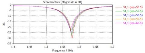
The influence of length (Wp) by the contribution of reflection coefficient (S11) is given in Figure 4.
In the case of a variation in the width of the patch, presented in Table 2 and Figure 5, show us that the bandwidth and the resonant frequency register minor downward variations while the reflection coefficient varies.
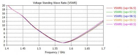
According to Figure 5, we notice that the VSWR gives us values ≤ 2, so we conclude that the width wp3 = 58.5 mm is the best width to improve the frequency band [1.555-1.595] GHz.
Figure 4. Influence of length (Wp) by the contribution of reflection coefficient (S11)
Figure 5. Influence of the width (Wp) by the standing wave ratio VSWR contribution
2.3 Influence of the thickness (hs) of the substrate
We will fix all the antenna parameters and change the value of the thickness (hs) of the substrate. The results obtained are identified in Table 3.
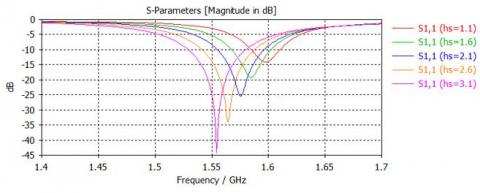
Figure 6 below clearly shows the variation of the thickness (hs) of the substrate on the parameter S11.
Table 1. Study the variation of the patch length (lp) on the antenna
|
lp (mm) |
Resonant Frequency (GHz) |
S11 |
Bandwidth |
VSWR |
Impedance |
|
42.2 |
1.645 |
-18.23 |
1.625- 1.666 |
1.27 |
54.5-1.64j |
|
43.2 |
1.609 |
-21.10 |
1.589-1.630 |
1.19 |
52.6-0.98j |
|
44.2 |
1.575 |
-24.80 |
1.555- 1.595 |
1.12 |
50.7-0.31j |
|
45.2 |
1.544 |
-30.43 |
1.523- 1.566 |
1.06 |
49.1-0.33j |
|
46.2 |
1.512 |
-44.40 |
1.492- 1.533 |
1.01 |
48.7-0.92j |
Table 2. Study the variation of the patch width (wp) on the antenna
|
Wp (mm) |
Resonant Frequency (GHz) |
S11 |
Bandwidth |
VSWR |
Impedance |
|
56.5 |
1.578 |
-30.29 |
1.558-1.601 |
1.06 |
52.5-2.1j |
|
57.5 |
1.576 |
-27.11 |
1.556-1.597 |
1.09 |
51.9-1.2j |
|
58.5 |
1.575 |
-24.80 |
1.555-1.595 |
1.12 |
50.7-0.31j |
|
59.5 |
1.574 |
-22.95 |
1.554-1.593 |
1.15 |
51.0-0.38j |
|
60.5 |
1.572 |
-21.50 |
1.552-1.590 |
1.18 |
49.7+0.22j |
Table 3. Study the variation of the substrate thickness (hs) on the antenna
|
hs (mm) |
Resonant Frequency (GHz) |
S11 |
Bandwidth |
VSWR |
Impedance |
|
1.1 |
1.597 |
-14.16 |
1.585-1.610 |
1.48 |
47.6j-3.2j |
|
1.6 |
1.584 |
-19.22 |
1.567-1.602 |
1.24 |
49.2-2.7j |
|
2.1 |
1.575 |
-24.80 |
1.555-1.595 |
1.12 |
50.7-0.31j |
|
2.6 |
1.564 |
-33.39 |
1.541-1.587 |
1.04 |
54.1+0.34j |
|
3.1 |
1.554 |
-44.13 |
1.529-1.580 |
1.01 |
59.2+0.85j |
Table 4. Study the variation of the microstrip line width (wf) on the antenna
|
wf (mm) |
Resonant Frequency (GHz) |
S11 |
Bandwidth |
VSWR |
Impedance |
|
2.11 |
1.564 |
-16.04 |
1.549-1.581 |
1.37 |
62.6-5.22j |
|
3.11 |
1.570 |
-20.07 |
1.552-1.589 |
1.22 |
59.2-2.9 j |
|
4.11 |
1.575 |
-24.80 |
1.555-1.595 |
1.12 |
50.7-0.31j |
|
5.11 |
1.580 |
-31.90 |
1.559-1.601 |
1.05 |
45.9-0.11j |
|
6.11 |
1.593 |
-52.0 |
1.563-1.607 |
1.02 |
38.2+2.15j |
Figure 6. Influence of thickness (hs) by the contribution of reflection coefficient (S11)
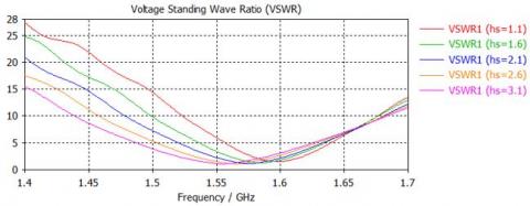
Figure 7. Influence of the thickness (hs) by the standing wave ratio VSWR contribution
Figure 6 shows that the bandwidth increases as the substrate thickness (hs) increase. Moreover, the resonant frequency decreases as the thickness (hs) grow. Therefore, the resonant frequency is inversely proportional to the substrate thickness (hs). On the other hand, the bandwidth is symmetrical to the thickness (hs) of the substrate.
The influence of the thickness (hs) of the substrate on VSWR is presented in Figure 7.
According to Figure 7 and the results of Table 3 obtained, the different thicknesses of the substrate (hs), the VSWR ≤ 2, so we conclude that the thickness hs3= 2.1 mm is the best to improve the frequency band [1.555-1.95] GHz.
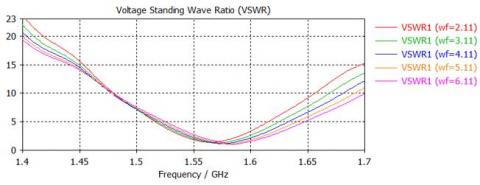
2.4 Influence of the width of the micro ribbon line wf
By changing the width of the microstrip line (wf), we distinguish the different variables according to Table 4.
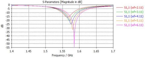
The influence of different widths line (wf) of the microstrip on the reflection coefficient (S11), and the VSWR are presented in Figures 8 and 9.
Figure 8. Influence of width (wf) by the contribution of reflection coefficient (S11)
According to the data in Table 4 and Figure 9, we note that with each increase in the microstrip line width (wf), the resonance frequency and bandwidth increase while the reflection coefficient changes.
According to Figure 9, we observe that for all the widths of the micro-strip line wf the VSWR ≤ 2, according to these results, we conclude that the width wf3= 4.11mm is the best to perfect the frequency band [1.555–1.595] GHz.
Figure 9. Influence of the width (wf) by the standing wave ratio VSWR contribution
2.5 Influence of the (gpf) width of the notch
We have found in the literature that adding a notch makes it better to fit the antenna fed by the microstrip line. The following Table 5 summarizes all of the notch width change results.
Table 5. Study the variation of the width of the notched (gpf) on the antenna
|
gpf (mm) |
Resonant Frequency (GHz) |
S11 |
Bandwidth |
VSWR |
Impedance |
|
0 |
1.556 |
-10.05 |
1.551-1.561 |
1.91 |
26.7-4.1j |
|
1 |
1.575 |
-24.80 |
1.555-1.595 |
1.12 |
50.7-0.31j |
|
2 |
1.575 |
-13.91 |
1.561-1.590 |
1.50 |
57.1+1.33j |
|
3 |
1.575 |
-10.51 |
1.570-1.573 |
1.84 |
51.23+5.6j |
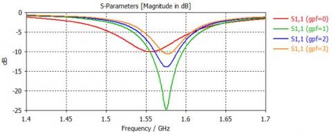
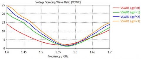
The notch width variation (gpf), in terms of the reflection coefficient S11 and VSWR, are shown in Figure 10 and Figure 11, respectively.
From the analysis of Figure 10, we find that the width (gpf) of the notch, for small values, the bandwidth decreases with the stability of the resonant frequency. On the other hand, when the value of (gpf) is zero, the adaptation between the microstrip line and the antenna is weak.
Figure 10. Influence of width (gpf) by input reflection coefficient (S11)
Figure 11. Influence of the (gpf) width by the standing wave ratio VSWR contribution
Figure 11 shows VSWR (dB) as frequency (GHz) function. Please note that our VSWR≤ 2 for all notch (gpf) widths used. Based on these results, we conclude that the width gpf2= 1 mm is better to improve the [1.555-1.595] GHz band.
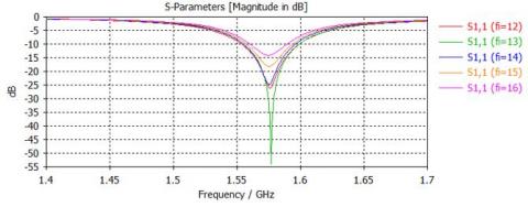
2.6 Influence of the length (fi) of the notch
The notched band is recommended to improve the adaptation between the microstrip line and the antenna. The following table shows some results on the variation of the values of the notch length.
The next curve gives the results of the influence of the length (fi) of the notch concerning the reflection coefficient S11.
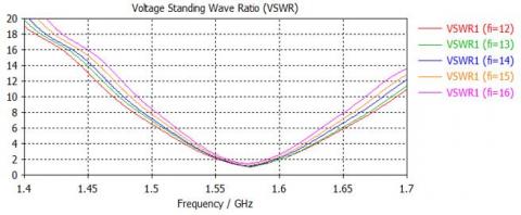
The curve above shows the results of the influence of the length (fi) of the notch concerning the VSWR.
Figure 12. Influence of length (fi) by the contribution of reflection coefficient (S11)
Figure 13. Influence of the length (fi) by the standing wave rate VSWR contribution
Table 6. Study the variation of the length of the notched (fi) on the antenna
|
fi (mm) |
Resonant Frequency (GHz) |
S11 |
Bandwidth |
VSWR |
Impedance |
|
12 |
1.576 |
-26.22 |
1.533-1.599 |
1.10 |
45.01+2.34 j |
|
13 |
1.577 |
-52.20 |
1.554-1.600 |
1.00 |
49.22-0.18 j |
|
14 |
1.575 |
-24.80 |
1.555-1.595 |
1.12 |
50.70-0.31j |
|
15 |
1.574 |
-18.22 |
1.558-1.594 |
1.27 |
55.43-2.55j |
|
16 |
1.573 |
-14.13 |
1.560-1.590 |
1.48 |
55.92-4.33 j |
Figure 12 indicates that the resonance frequency remains almost the same for different lengths with a very slight variation, while the level of S11 is varied.
On the other hand, through Figure 13 and Table 6, we noticed that by making all the changes related to the (gpf) length of the notch, the VSWR always remains less than or equal to 2 (VSWR≤2).
From the studies we have done, we note that for the resonant frequency equal to 1.575 GHz, we find that the impedance is Z = 50.7-0.31j, so we can say that when the fundamental part of impedance input reaches its maximum, the imaginary part vanishes.
We can deduce the final parameters to improve the frequency band; see Table 7 below.
After designing the antenna, we simulate the latter's operation, which was intended for the GPS application.
The results obtained by studying this antenna are represented in several parameters, the most important: the reflection coefficient (S11), VSWR, and the radiation pattern, which are shown in the figures below.
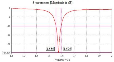
Figure 14 shows the result of the simulation of the reflection coefficient S11 (dB) as a function of frequency (GHz). We observed that the antenna showed a good adaptation in the band [1.555-1.595] GHz, so the reflection coefficient is less than -10dB, then the latter is the smallest at the resonance frequency of 1.575 GHz at - 24.804dB.
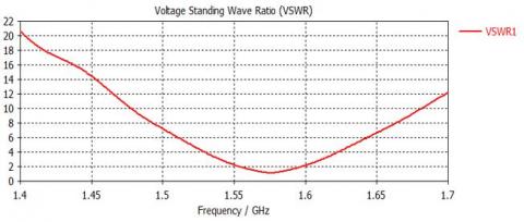
Figure 15 determines the result of the standing wave ratio VSWR as a function of frequency (GHz). The figure shows that VSWR ≤ 2 corresponds to S11 ≤ − 10 dB in the same frequency band (1.555-1.595) GHz.
CST software makes it possible to visualize the radiation diagram in gain and directivity after the simulation (Figures 16 (a) and (b)). We observe that the radiation diagram of this antenna is oriented in the Z direction. We note that the gain and directivity are positive when the antenna radiates on the 1.575 GHz frequency band.
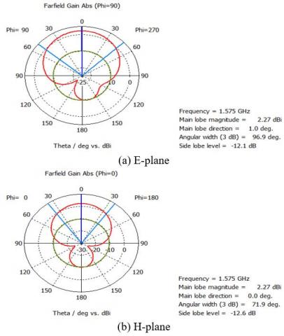
Figure 17 shows the radiation patterns in two planes: E and H, for the antenna frequency, studied (1.575 GHz).
From Figure 17, the antenna radiates in the direction (θ= 0°). The angular widths are 96.9° and 71.9° in the E-plan and H-plane, respectively. The corresponding side lobe levels are -12.1 dB and -12.6 dB.
Figure 14. Reflection coefficient (S11) of the proposed antenna
Figure 15. VSWR of the proposed antenna
Table 7. Size of the optimized antenna
|
Parameter |
Dimensions (mm) |
The Type of Materials Used |
|
Substrate width (ws) |
95 |
FR-4 (lossy) |
|
Substrate length (ls) |
82 |
// |
|
Substrate thickness (hs) |
2.1 |
// |
|
Patch width (Wp) |
58.5 |
Copper (anneded) |
|
Patch length (lp) |
44.2 |
// |
|
Notch thickness (ht) |
0.05 |
// |
|
Ground plane width (wg) |
95 |
// |
|
Ground plane length (lg) |
82 |
// |
|
Ground plane thickness (ht) |
0.05 |
// |
|
Line length (wf) |
4.11 |
// |
|
Line width (wf) |
26.31 |
// |
|
Notch length (fi) |
14 |
|
|
Notch width (gpf) |
1 |
|
Table 8. Comparison of the proposed antenna with related works
|
Ref |
Size (mm3) |
Array area (mm2) |
Volume (mm3) |
Bandwidth (GHz) |
Resonant Frequency (GHz) |
|
[17] |
127.5×127.5×1.6 |
16256,25 |
26010 |
1.5831-1.589 |
1.58 |
|
[18] |
D=125*, h=9.525 |
12265,625 |
116830,07 |
1.55-1.65 |
≈1.61 |
|
[19] |
120×120×1.6 D=76*, h=28 |
14400 |
149996,48 |
1.5-1.6 |
1.56 |
|
[20] |
130×130×1.52 80.8×80.8×30 |
16900 |
217688 |
1.563-1.587 |
1.575 |
|
[21] |
85.5×85.5×5.62 |
7310,25 |
41083,605 |
1.435-1.715 |
1.575 |
|
[22] |
D=70*, h=20 |
3846,5 |
76930 |
1.568-1.581 |
1.575 |
|
[23] |
113×113×33 |
12769 |
174469 |
1.260-2.210 |
1.575 |
|
Proposed |
95×82×2.1 |
7790 |
16359 |
1.555-1.595 |
1.575 |
* The circular shape with D is the diameter (mm), and h is the thickness
Figure 16. 3D radiation patterns of proposed antenna
Figure 17. 2D gain radiation pattern
To give significance to the proposed antenna, a comparison with recently proposed antennas is necessary. The performance of the proposed antenna is compared with recently proposed antennas in the literature is given in Table 8.
The two sizes [19] are the antenna's size and the dielectric resonator. The two sizes are those of the antenna and the reflector [20].
According to Table 8, the proposed antenna has a good array area and good occupied volume.
A microstrip patch antenna has been proposed and investigated for GPS application. The proposed antenna has compact dimensions of 95×82×2.1 mm3. The antenna is designed to operate in the GPS band frequency from 1.555 GHz to 1.595 GHz and resonates at 1.575 GHz with a return loss of -24.804 dB. The material used for the substrate is FR-4, with relative permittivity of 4.3. The performance analysis of the proposed antennas has been tested by the obtained values of the return loss (dB), gain (dB), and VSWR. The obtained results verify the satisfactory performance of the proposed antenna for GPS application.
The following steps to deepen this study are the miniaturization of the antenna's dimensions in future work. In the second part, the antenna's operating frequency must be extended to multiband to support other ranges of applications.
This research was supported by the collaboration of University of Bouira, Algeria (PRFU N°: A10N01UN100120220001) and Taif University Researchers Supporting Project Number TURSP-2020/34, Taif University, Taif, Saudi Arabia.
[1] Zhang, C., Xue, W., Xin, Y. (2019). Design and application of an intelligent patrol algorithm for forest management and protection based on global positioning system. Ingénierie des Systèmes d'Information, 24(6): 597-602. https://doi.org/10.18280/isi.240606
[2] Bandyopadhyay, M., Mandal, N., Chattopadhyay, S., Roy, B. (2017). A novel GSM and GPS based vehicle security system. Advances in Modelling and Analysis D, 22(1): 62-76. https://doi.org/10.18280/ama_d.220105
[3] Plaza, J., Palacios, C., Abecia, J.A., Nieto, J., Sánchez-García, M., Sánchez, N. (2022). GPS monitoring reveals circadian rhythmicity in free-grazing sheep. Applied Animal Behaviour Science, 251: 105643. https://doi.org/10.1016/j.applanim.2022.105643
[4] Razin, M.R.G., Voosoghi, B. (2022). Modeling of precipitable water vapor from GPS observations using machine learning and tomography methods. Advances in Space Research, 69: 2671-2681. https://doi.org/10.1016/j.asr.2022.01.003
[5] Poliziani, C., Rupi, F., Schweizer, J. (2022). Traffic surveys and GPS traces to explore patterns in cyclist’s in-motion speeds. Transportation Research Procedia, 60: 410-417. https://doi.org/10.1016/j.trpro.2021.12.053
[6] Tran, Q.H., Fang, Y.M., Chou, T.Y., Hoang, T.V., Wang, C.T., Vu, V.T., Chen, M.H. (2022). Short-term traffic speed forecasting model for a parallel multi-lane arterial road using GPS-monitored data based on deep learning approach. Sustainability, 14(10): 6351. https://doi.org/10.3390/su14106351
[7] Hilal, H.A., Hilal, N.A., Hilal, T.A. (2022). Crowdsensing application on coalition game using GPS and IoT parking in smart cities. Procedia Computer Science, 201: 535-542. https://doi.org/10.1016/j.procs.2022.03.069
[8] Arshad, J., Rehman, A.U., Othman, M.T.B., Ahmad, M., Tariq, H.B., Khalid, M.A., Hamam, H. (2022). Deployment of wireless sensor network and IoT platform to implement an intelligent animal monitoring system. Sustainability, 14(10): 6249. https://doi.org/10.3390/su14106249
[9] Shi, Y., Yang, T., Zhang, S., Liu, L., Cui, Y. (2020). A Wi-Fi positioning system for material transport in greenhouses. Instrumentation Mesures Métrologies, 19(1): 65-72. https://doi.org/10.18280/i2m.190109
[10] Wei, X., Aman, M., Sikdar, B. (2021). Exploiting correlation among GPS signals to detect GPS spoofing in power grids. IEEE Transactions on Industry Applications, 58(1): 2022. https://doi.org/10.1109/TIA.2021.3131970
[11] El Yassini, A., Jallal, M.A, Ibnyaich, S., Zeroual, A., Chabaa, S. (2020). A miniaturized CPW-fed reconfigurable antenna with a single-dual band and an asymmetric ground plane for switchable band wireless applications. Traitement du Signal, 37(4): 633-638. https://doi.org/10.18280/ts.370412
[12] Gao, Y., Lu, H. (2019). A novel co-planar waveguide-fed direct current wide band printed dipole antenna. Traitement du Signal, 36(3): 253-257. https://doi.org/10.18280/ts.360308
[13] Farooq, U., Rather, G.M. (2019). Design and analysis of rectangular microstrip antenna (RMSA) for millimeter wave communication applications. Traitement du Signal, 36(5): 433-438. https://doi.org/10.18280/ts.360508
[14] Kumar, S., Dixit, A.S. (2021). A miniaturized CSRR loaded 2-element MIMO antenna for LTE band. Mathematical Modelling of Engineering Problems, 8(6): 984-988. https://doi.org/10.18280/mmep.080620
[15] Basit,A., Khattak, M.I., Sebak,R., Qazi, A., Telba,A. (2020). Design of a compact microstrip triple independently controlled pass bands filter for GSM, GPS and WiFi applications. IEEE Access, 8: 77156-77163. https://doi.org/10.1109/ACCESS.2020.2989377
[16] Liu, H., Shi, M., Fang, S., Wang, Z. (2020). Design of low-profile dual-band printed quadrifilar helix antenna with wide beamwidth for UAV GPS applications. IEEE Access, 8: 157541-145548. https://doi.org/10.1109/ACCESS.2020.3018906
[17] Supriya, A.S., Rajendran, J. (2017). A low cost tri-band microstrip patch antenna for GPS application. IEEE in 2017 Progress in Electromagnetics Research Symposium-Fall (PIERS-FALL), pp. 60-65. https://doi.org/10.1109/PIERS-FALL.2017.829311
[18] Awais, M., Madni, A., Khan, W.T. (2022). Design of a compact high isolation 4-element wideband patch antenna array for GNSS applications. IEEE Access, 10: 13780-13786. https://doi.org/10.1109/ACCESS.2022.3147600
[19] Sharma, A., Das, G., Gupta, S., Gangwar, R.K. (2020). Quad-band quad-sense circularly polarized dielectric resonator antenna for GPS/CNSS/WLAN/WiMAX applications. IEEE Antenna and Wireless Propagation Letter, 19(3): 403-407. https://doi.org/10.1109/LAWP.2020.2969743
[20] Lee, S., Yang, Y., Lee, K.Y., Hwang, K.C. (2020). Dual-band circularly polarized annular slot antenna with a lumped inductor for GPS application. IEEE Transaction on Antennna and Propagation, 68(12): 8197-8202. https://doi.org/10.1109/TAP.2020.2997990
[21] Joshi, R., Hussin, E.F.N.M., Soh, P.J., Jamlos, M.F., Lago, H., Al-Hadi, A.A., Podilchak, S.K. (2020). Dual-band, dual-sense textile antenna with AMC backing for localization using GPS and WBAN/WLAN. IEEE Access, 8: 89468-89478. https://doi.org/10.1109/ACCESS.2020.2993371
[22] Zhong, Z.P., Zhang, X., Liang, J.J., Han, C.Z., Fan, M.L., Huang, G.L., Yuan, T. (2019). A compact dual-band circularly polarized antenna with wide axial-ratio beamwidth for vehicle GPS satellite navigation application. IEEE Transactions on Vehicular Technology, 68(9): 8683-8692. https://doi.org/10.1109/TVT.2019.2920520
[23] Pourbagher, M., Nourinia, J., Ghobadi, C. (2020). Circularly polarized printed crossed-dipole antenna using branch-line feed network for GPS applications. AEU-International Journal of Electronics and Communications, 120: 153226. https://doi.org/10.1016/j.aeue.2020.153226