Sarala Patchala* | Sailaja Maruvada
© 2021 IIETA. This article is published by IIETA and is licensed under the CC BY 4.0 license (http://creativecommons.org/licenses/by/4.0/).
OPEN ACCESS
Filter Bank Multicarrier (FBMC) frameworks are a subclass of multicarrier (MC) frameworks. The essential guideline, separating spectrum into many thin sub channels, may not be new, MC frameworks have seen wide appropriation. These days, multicarrier regulation frameworks dependent on the discrete Fourier transforms are usually used to transmit over recurrence particular channels subject to forceful noise aggravations. In any case, these handsets experience the ill effects of poor sub channel spectral control, that is, the measure of inter channel impedance isn't unimportant. It very well may be indicated that the framework execution reduces when it is dependent upon an unsettling influence with a large portion of its energy focused on a narrow frequency band. This Paper aims that identify the Filter Bank Multi Carrier (FBMC) performance. The MIMO system combined with the FBMC then identifies the over Frequency Selective Channel (FSC). Here the analysis for FSC, Flat fading model FBMC and system with MMSE equalization. The Prototype filters are analyzing the system performance characteristics. The Power Spectral Density (PSD) of the MIMO FBMC system for the given spectrum. The proposed systems are best to compare all existing technique and we measure the spectral efficiency of the system.
FBMC, MIMO, OFDM, multicarrier regulation frameworks, noise aggravations, spectrum
The Wireless Communications Systems (WCS) through the 4G the numbers of users are to increase and improve the available spectrum more effectively [1-3]. Where in 1G WCS is Analog Cellular based on Analog Signal. The 1G drawbacks overcome in 2G WCS to achieve fast development. The 2G also called Narrowband digital WCS. In 3G standards are WCDMA, CDMA, and SCDMA. To meets the High Data requirements the 4G standards in 2008. In 5G to meet up to 10Gbps data rate for the WCS [4-6]. Now concentrate on the FBMC multi-carrier system for the 5G WCS with more and more effectively. In the present scenario, the MIMO technique with better quality and High Data rates for both transmitting & receiving antennas [7]. The MIMO system is used to boost the performance of WCS. The FBMC is an attractive research topic which includes minimizing the transmit power while attaining Quality of Service.
As of late the interest in spectrum is consistently developing. The constrained measure of accessible spectrum, Pooling of Spectrum has increased tremendous ubiquity. In different examinations, it is clear that vast majority of the authorized spectrum leftovers underutilized. Spectrum Pooling focuses on taking advantage of the spaces in the authorized spectrum. The unused spectrum is normally accessible in chunks. In such a situation, multicarrier communication which transmits information over a channel in a few recurrence subcarriers with a lower information rate is picked up unmistakable quality. Its intrigue lies in the way that it battles recurrence particular blurring.
FBMC modulation is a multicarrier balance technique where amalgamation channels are utilized at transmitter side and recipient side separately [8]. The filters contain lot of bandpass filters that are recurrently moved or adjusted renditions of a model low pass filter. FBMC offers spectrum control over OFDM as the channel data transfer capacity, and hence selectivity, is a boundary that can be fluctuated during lowpass model structure [9]. It likewise offers better data transmission proficiency when contrasted with OFDM. The general Filter bank Multicarrier (FBMC) transmitter is depicted in Figure 1.
Figure 1. Filter bank Multicarrier (FBMC) transmitter
MC modulation has a long-standing account in wireless networks be that as it may, across the practical applications that have just been acknowledged in the most recent renditions of remote frameworks as OFDM, empowered by propels in incorporated circuits. In the past OFDM is the most advanced method in a wired and wireless communication system. The OFDM is used in the IEEE standards 802.11, 802.16, LTE & LTE Advanced. OFDM faces several problems like spectral leakage, out of band and loss in bandwidth efficiency [10]. The carrier systems are based on transmission two types (i.e., Single and Multiple Carrier systems). The Spectral Efficiency improvement is the main challenge in this paper with the MMSE technique, over the FSC. These problems over come in the FBMC system. The FBMC with the MIMO channels over the frequency based on the channels and for the selective channels. The FBMC multi-carrier system compares with the Universal Multi Carrier signal Modulation System, OFDM system [11]. Here the Table 1 compares the different parameters Out of band, Orthogonal, PAPR, Latency and spectral efficiency of the OFDM, UFMC and FBMC system. The FBMC carried out in the PHYDAS project.
Table 1. Comparison between OFDM, UFMC & FBMC
|
S.NO |
Parameter |
OFDM |
UFMC |
FBMC |
|
1 |
Out of band |
High |
Low |
Low |
|
2 |
Orthogonal |
Yes |
Yes |
Yes |
|
3 |
PAPR |
High |
Medium |
High |
|
4 |
Latency |
Short |
Short |
Short |
|
5 |
Spectral Efficiency |
Medium |
High |
High |
In Multi-carrier modulation system the information is transmitted over pulses, which usually overlap in the Time & Frequency domain. The drawback is the pulses occupy only a small bandwidth [12]. SoFSC transforms into multiple sub-channels with negligible interference [13]. Consider N QAM symbols in duration T in Discrete Time Domain. Mathematically in the time domain signal is:
$s(t)=\sum_{n=-\infty}^{\infty} \sum_{m=0}^{N-1} a_{m, n} P\left(t-n \frac{T}{2}\right) e^{-i 2 \pi m F t} e^{-i \emptyset_{m, n}}$ (1)
where, m is the Frequency Index and n is the Time Index.
T is the interval between symbols in time.
The summaries of contributions are as follows:
Multicarrier systems are well suited to the time - frequency variability of propagation channels, making equalisation easier. This is particularly appealing for mobile channels of communication that experience multipath propagation and change regularly over time. Multicarrier methods use multiple modulation languages and power allocation for the various subcarriers to conform to the carrier frequency of the channel. In this way, a close comparison to the waterfilling solution can be obtained, and the usable bandwidth can be used to its full potential. There are many existing models for frequency selective channels that have observed low performance levels and the time complexity is more. There is a necessity to implement a model that achieves better accuracy rate. The paper is organized as in Section II system model review. In the Section III system Frequency selective FBMC. In Section IV proposed system simulation results for the Proto Type Filters response, Normalized Filter Response, FBMC compared with OFDM system response for the subcarriers along with overlapping factor.
The existing multicarrier methods utilized filter banks, which frameworks can be structured with little side lobes settling on them an ideal decision for different contact and psychological radio applications [14]. The filter banks proceeded with other option and progressively proficient methods of execution. DFT based, cosine adjusted exponential balanced filter banks are a portion of choices that are contemplated [15]. The various arrangements of DFT based filter banks and conditions for immaculate recreation were concentrated to locate the ideal techniques. In later a long time the center has moved to increasingly explicit zones.
Oversampled and fundamentally examined DFT modulated channel keeps money with immaculate reproduction structure is considered [16]. An oversampled fundamental FIR NPR model is built for DFT regulated filter banks dependent on adjusted Newtons calculation, which is required to permit low framework delays. DFT that displays high time-frequency (TF) focus in which TF-deciphered variants of a model pane establish a symmetrical set introduced required to convey maximal TF resolutions [17].
A perfect filter is a gadget that gives alteration less broadcast over assured recurrence groups and zero reaction at different frequencies. They are utilized to dispense with undesirable parts or then again highlights, for example, obstruction, commotion and contortion items from a sign that is bearing data [18]. Consequently filter are prepared to do permitting and dismissing frequencies specifically. Then again, filter can be characterized as electrical systems that alter the sufficiency and stage parts of a sign concerning recurrence.
Kim et al. [2] developed the concept and demonstrated how Chang's method could be changed to transmit QAM symbols in a DSB-modulated format. Saltzberg suggested that the in-phase and sine and cosine components of each QAM symbol be time spaced by half a symbol interval to retain the high throughput of this system comparable to Chang's signalling.
Currently, only a small amount of research has been done on this topic by Hassan and Fernando [4]. The optimisation of using PR architecture in FBMC was challenged in a recent analysis on FBMC, but the authors left it as an active problem. In fact, some works that use CP instead of the original FBMC have shown the viability of dropping the PR condition. Kong et al. [7] suggested combining OFDM with FBMC, which reduces the symbol rate by half since only half of its subbands are activated for each data block, effectively restoring orthogonality in the time domain. Only a selection of the (active) subcarriers are used as pilot tones in model proposed by Wang and Tian [9], with the rest holding information symbols. The subchannel reply estimates are computed using an iterative (EM-based) algorithm, similar to joint estimation/detection. Based on frequency sampling, subchannel measurements were also calculated by Prasad et al. [11]. Wang et al. [12] was the first to calculate the channel impulse response (CIR). The key concept was to model the subchannel CFRs as Taylor polynomials, with the order reflecting the frequency selectivity of the subchannels. This, combined with the use of a channel path-delay model, resulted in an estimation method that treats the problem as an array processing problem.
Filters may be simple or advanced, containing various sorts and requests. Filters are named detached or dynamic relying upon the segments. An uninvolved filter is completed utilizing inactive segments like resistors, capacitors and inductors, while dynamic filters utilize operational speakers as the dynamic part notwithstanding utilizing resistors and capacitors.
The main FBMC systems are classified into 3 types. These are built based on original CMT, built based on the extension and built based on the conventional FDM (Frequency Division Multiplexing). Many of the researchers are concentrate on the SMT and CMT systems with different scenarios. The main scenarios are to cancel the (ISI) Internal Symbol Interference and (ICI) Inter-Carrier Interference. In the CMT the data symbols from the PAM modulated and real-valued to establish the transmission with the maximum efficiency of the bandwidth.
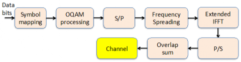
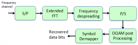
In the PAM symbols are distributed in the Time to Frequency phase to space lattice the density were two symbols/unit area. Where carrier spacing is $F=1 / 2 T$. The pulse shape used for the Transmitter as well as for the Matched Filter at the Receiver is Square Root Nyquist Waveform. The Figure 2 represents the FBMC transmitter process and Figure 3 represents the FBMC receiver process.
Figure 2. FBMC transmitter process
Figure 3. FBMC receiver
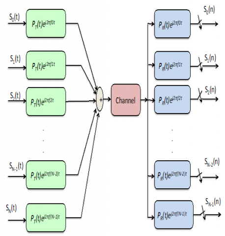
Figure 4. MIMO-FBMC communication system model prototype filter design
The Figure 4 indicates the MIMO-FBMC system model prototype filter design. The MIMO technique combined FBMC by eliminating the intrinsic interference. The duration of the $P_{T}(t)>T$ and $P_{R}(t)>T$ are integral multiples of $\mathrm{T}$. Hence, $T=T_{F F T}=\frac{1}{B}$.
The Transmit signal defined as:
$s_{k}(t)=\sum s_{k}(n) \delta(t-n T)$ (2)
where, k is subcarrier index and T is symbol time spacing $s_{k}(n)^{\prime}$ are the sub-carrier data symbol.
In OFDM the pulse PT(t) is a Rectangular pulse of height one &width T. The receiver prototype filter PR(t) is a rectangular pulse of height one. OFDM prototype filters response suffers from large side lobes in the Frequency Domain.
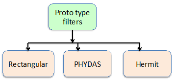
The prototype filters for the time invariant channels. The square root raised cosine filters are used to get a better response. Select the proper filter to get the better filter magnitude response. The Figure 5 indicates the types of prototype filters.
Figure 5. Types of proto type filters
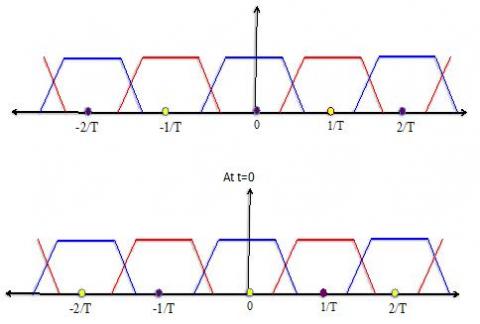
Here, the subcarriers are modulated to frequencies $+0, \pm \frac{1}{T}, \pm \frac{2}{T}, \ldots$ etc.
4.1 Proposed MIMO frequency selective FBMC
The FBMC with the independent data sub-channels with high spectrum resolution enhanced data rates. The FBMC is very helpful for the Dynamic Spectrum allocation of resources in the Physical Layer. The MIMO based Frequency selective FBMC is given by:
$s(k)=\sum_{n=-\infty}^{\infty} \sum_{m=0}^{M-1} a_{m, n} g_{m, n}(k)$ (3)
gm,n(k) is real value prototype Filter. Fast implementation of FBMC based on frequency spreading or dispreading.
$g_{m, n}(k)=p(k-n m) e^{j \frac{2 \pi}{N} m k} e^{j \emptyset_{m, n}}$ (4)
$I \mathrm{term}=\sum_{k=-\infty}^{\infty} \sum_{t=1}^{N_{t}} \sum_{l=0}^{L_{h}-1} h_{r t}(l) s_{t}(k-l) g_{u, v}^{*}(k)$ (5)
II term $=\sum_{k=-\infty}^{\infty} g_{u, v}^{*}(k) \eta_{r}(k)$ (6)
The signal part is,
$\sum_{k==-\infty}^{\infty} \sum_{t=1}^{N_{t}} \sum_{l=0}^{L_{h}-1} h_{r t}(l) s_{t}(k-l) g_{u, v}^{*}(k)$ (7)
The data symbols in the proposed model come from such a pulse amplitude modulated (PAM) alphabet and are thus real-valued. PAM symbols are transmitted in a time-frequency sequence lattice with a frequency of two symbols per unit area to create a transmission with maximum bandwidth efficiency. This is the same as one dynamic symbol per square metre. Furthermore, a 90-degree phase change is applied to the specific carriers even amongst the adjacent symbols for the reasons explained below.
After transmission over a channel, data is decoded by anticipating the received signal, f(t), onto the premise beats, rl,f (t), that is,
$\operatorname{Sg}(\mathrm{t})=\{\mathrm{f}(\mathrm{t}), \mathrm{r} 1, \mathrm{f}(\mathrm{t})\}=\sum_{m=0}^{M-1} a_{t, m, n}+e^{j \frac{2 \pi}{N} m(k-l)}$ (8)
The above equation can be simplified into by substituting s(k), gm,n(k).
$s_{t}(k)=\sum_{n=-\infty}^{\infty} \sum_{m=0}^{M-1} a_{t, m, n} g_{m, n}(k)=\sum_{n=-\infty}^{\infty} \sum_{m=0}^{M-1} a_{t, m, n} p(k-n m) e^{j \frac{2 \pi}{N} m k} e^{j \emptyset_{m, n}}$ (9)
$s_{t}(k-l)=\sum_{n=-\infty}^{\infty} \sum_{m=0}^{M-1} a_{t, m, n} g_{m, n}(k-l)=\sum_{n=-\infty}^{\infty} \sum_{m=0}^{M-1} a_{t, m, n} p(k-n m-l) e^{j \frac{2 \pi}{N} m(k-l)} e^{j \emptyset_{m, n}}$ (10)
The Frequency selective MIMO based FBMC is given by:
$\sum_{k=-\infty}^{\infty} \sum_{t=1}^{N_{t}} \sum_{l=0}^{L_{h}-1} h_{r t}(l) s_{t}(k-l) g_{u, v}^{*}(k)$ (11)
4.1.1 Frequency selective channels
The signal part can be further simplified as:
From the Eq. (11).
$\sum_{k=-\infty}^{\infty} \sum_{t=1}^{N_{t}} \sum_{l=0}^{L_{h}-1} h_{r t}(l) s_{t}(k-l) g_{u, v}^{*}(k)$
$=\sum_{k=-\infty}^{\infty} \sum_{t=1}^{N_{t}} \sum_{l=0}^{L_{h}-1} h_{r t}(l) \sum_{n=-\infty}^{\infty} \sum_{m=0}^{M-1} a_{t, m, n} p(k-n m-l) e^{j \frac{2 \pi}{N} m(k-l)} e^{j \emptyset_{m, n}} g_{u, v}^{*}(k)$
$=\sum_{k=-\infty}^{\infty} \sum_{t=1}^{N_{t}} \sum_{l=0}^{L_{h}-1} h_{r t}(l) \sum_{n=-\infty}^{\infty} \sum_{m=0}^{M-1} a_{t, m, n} p(k-n M) e^{j \frac{2 \pi}{N} m(k-l)} e^{j \emptyset_{m, n}} g_{u, v}^{*}(k)$
$=\sum_{k=-\infty}^{\infty} \sum_{t=1}^{N_{t}} \sum_{l=0}^{L_{h}-1} h_{r t}(l) \sum_{n=-\infty}^{\infty} \sum_{m=0}^{M-1} a_{t, m, n} g_{m, n}(k) g_{u, v}^{*}(k)$
$=\sum_{t=1}^{\infty} \sum_{n=-\infty}^{\infty} \sum_{m=0}^{M-1} a_{t, m, n} H_{r, t}(m) \xi_{m, n}^{u v}$
$p(k-n m-l) \approx p(k-n M)$
$\sum_{k=-\infty}^{\infty} g_{m, n}(k) g_{u, v}^{*}(k)=\xi_{m, n}^{u v}$
$\sum_{n=-\infty}^{\infty} \sum_{m=0}^{M-1} g_{t, m, n} \cup_{v=0}^{u-1} \mathrm{f}(\mathrm{m}, \mathrm{n}) U_{u=0}^{v-0} \frac{f(m, n)}{f_{\max }}$
$\sum_{k=-\infty}^{\infty} \sum_{t=1}^{N_{t}} \sum_{l=0}^{L_{h}-1} h_{r t}(l) s_{t}(k-l) g_{u, v}^{*}(k)=\sum_{t=1}^{\infty} \sum_{n=-\infty}^{\infty} \sum_{m=0}^{M-1} a_{t, m, n} H_{r, t}(m) \xi_{m, n}^{u v}$ (12)
The MIMO –FBMC system as follows:
$\tilde{r}_{r, u, v}=\left[\begin{array}{c}\tilde{r}_{1, u, v} \\ \tilde{r}_{2, u, v} \\ \tilde{r}_{3, u, v} \\ \cdot \\ \tilde{r}_{3 u, v}\end{array}\right] a_{t, u, v}=\left[\begin{array}{c}a_{1, u, v} \\ a_{2, u, v} \\ a_{3, u, v}\\ \cdot \\ a_{N t, u, v}\end{array}\right] I_{r, u, v}=\left[\begin{array}{c}I_{1, u, v} \\ I_{2, u, v} \\ I_{3, u, v} \\ \cdot\\ I_{N t, u, v}\end{array}\right] \eta_{r, u, v}=\left[\begin{array}{c}\eta_{1, u, v} \\ \eta_{2, u, v} \\ \eta_{3, u, v} \\ \cdot\\ \eta_{N t, u, v}\end{array}\right]$
$\tilde{r}_{r, u, v}=\sum_{t=1}^{N_{t}} H_{r, t}(u) a_{t, u, v}+I_{r, u, v}+\eta_{r, u, v}$ (13)
4.1.2 Flat Fading Model MIMO-FBMC
The MIMO model across subcarrier u is for symbol time v is:
$\tilde{r}_{u, v}=H(u) a_{u, v}+I_{u, v}+\eta_{u, v}$ (14)
By using Zero force Receiver is given as:
$\tilde{r}_{u, v}=H(u) a_{u, v}+I_{u, v}+\eta_{u, v}$
$\rightarrow \tilde{a}_{u, v}=(H(u))^{-1} \tilde{r}_{u, v}$
4.1.3 FBMC systems MMSE equalization
The MMSE design is to get the optimized performance. The MMSE is widely in linear MMSE Equalization of FBMC system the optimization problem is:
$w_{k, M M S E}=\arg \left\{\min \left\{E\left[\left|a_{k}(m)-a_{k}(m-v)^{2}\right|\right.\right.\right.$
V is equalization delay.
$y_{k}[n]=\left[y_{k}[n], y_{k}[n-1], y_{k}[n-2], y_{k}[n-3], \ldots \ldots . y_{k}\left[n-N_{1}\right]\right]^{T}$ (15)
The FBMC system is given by:
$r(k)=\sum_{l=0}^{n-1} h(l) s(k-l)+n(k)$ (16)
$r_{u, v}=\sum_{k=-\infty}^{+\infty} r(k) g_{u, v}^{*}(k)$
$s(k)=\sum_{n=-\infty}^{\infty} \sum_{m=0}^{M-1} a_{m, n} g_{m, n}(k)$ (17)
$r(k)=\sum_{l=0}^{n-1} h(l) \sum_{n=-\infty}^{\infty} \sum_{n=-\infty}^{M-1} a_{m, n} g_{m, n}(k-l)$ (18)
$g_{m, n}(k)=p(k-n m) e^{j \frac{2 \pi}{N} m k} e^{j \emptyset_{m, n}}=\sqrt{\sum_{n=1}^{M} \mathrm{~h}(\mathrm{l}) * a_{m, n}(k-1)+g^{n}+n(k)}$
$\operatorname{Ch}(t)=\sigma_{F}(t)+\sqrt{\sum_{n=1}^{M} a_{m, n}(k-1)+\sum_{n=-\infty}^{M-1} g(k) a(m-l)}$ (19)
MMSE algorithm needs to know the statistical information of the channel in advance [19].
4.2 Power Spectral Density (PSD)
The PSD of a Wide Sense Stationary random process as the Fourier transform of the autocorrelation function.
$S_{x x}(w)=\int_{-\infty}^{\infty} R_{X X}(\tau) e^{-j w \tau} d \tau$ (20)
4.3 Spectral efficiency of an FBMC system
In FBMC the prototype filter must be a real-valued even function.
$P(t)=P(-t)$ (21)
And for orthogonal for Time-Frequency spacing of T ×F=TF=2. To improve the spectral efficiency in FBMC, the time spacing as well as the frequency spacing, are both reduced by a factor of 2. Moreover, our aim to achieves high spectral efficiency.
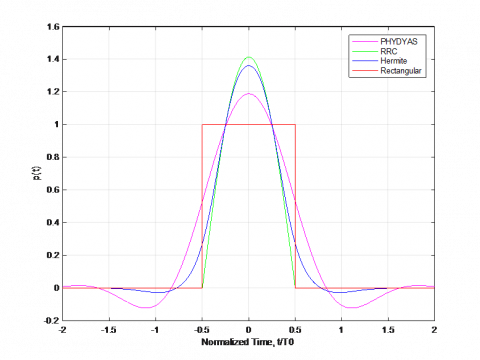
The Different prototype filters and their response w.r.t normalized time t/T0 as shown in Figure 6. The fig illustrates that PHYDAS filter, RRC, Hermite and rectangular filters. The Rectangular pulse with a Time from -0.5 to 1. The Normalized Filter Responses are as shown in Figure 7. The proposed model response levels are better when compared to traditional models. As the filter response time levels of the proposed model is better, the channel selection will also be accurate. The Phydas prototype filter with an overlapping factor of 4 and where Hermite prototype filter with an overlapping factor of 8 is used. The Phydas is more suits and preferred for the FBMC system.
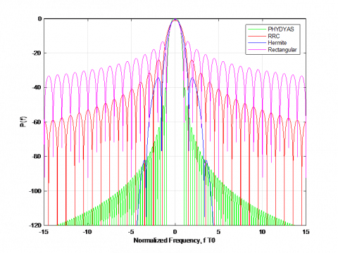
The prototype filters normalized response is indicated in Figure 8. The proposed model is compared to traditional methods and the graphs are included clearly. The proposed model normalized response is accurate then the existing models.
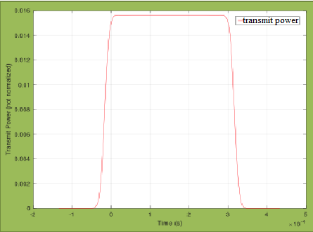
The PSD of the FBMC system and its transmitted power are observed in Figure 9. Here the normalized transmitted power spectrums from the o to 0.016. The PSD of the transmit signals in the FBMC system with proposed channel estimation subcarriers. A PSD is a metric that compares the power content of a signal to its frequency. Broadband random signals are usually defined using a PSD. The spectral resolution used to digitise the signal is used to normalise the PSD's amplitude.
Figure 6. Subcarriers spectra
Figure 7. Prototype filter response
Figure 8. Prototype filters normalized response
Figure 9. Power spectral density
(a)
(b)
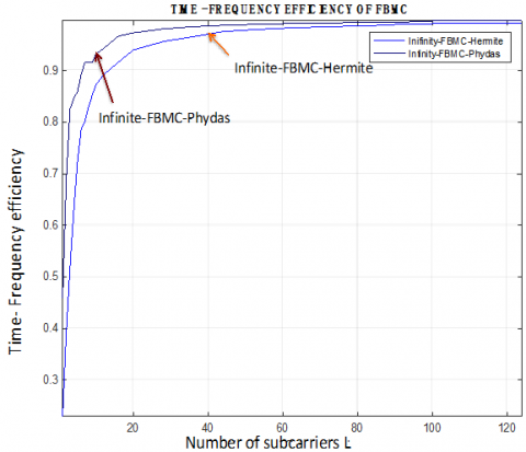
Figure 10. Time-frequency spectral efficiency of FBMC
The transmitted power over the 4 sub-carriers with 10 FBMC symbols the Hermite Prototype filter transmitted power with time as illustrated in Figure 10. The corresponding FBMC with OQAM with no channel information its PSD for Frequency in terms of Hz. The input rate that can be distributed over a given bandwidth in a communication system is referred to as spectral efficiency, spectrum efficiency, or bandwidth efficiency. It's a metric for how often the physical layer protocol, and often the medium access control, uses a finite frequency range.
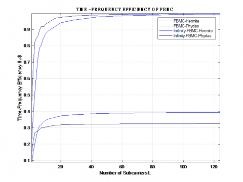
The Figure 10 illustrates that the Time-Frequency Spectral Efficiency of FBMC system. The time Frequency efficiency with respect to the number of carrier L=124. Figure 10 (a) gives that the FBMC-Hermite and FBMC-Phydas response of the spectral efficiency with the overlapping factor of K=1, the number of FFT points N=2048.The infinity case of FBMC-Hermite and FBMC-Phydas are as shown in Figure 10 (b). The Figure 11 compares all the existing cases for the Time-Frequency spectral efficiency of the FBMC system. The FBMC modulator with 4 carriers off is depicted in Figure 11.
Figure 11. FBMC modulator with 4 carriers off
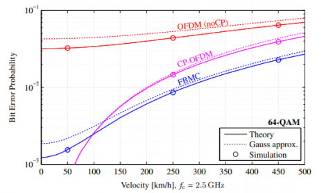
Figure 12. Error probability
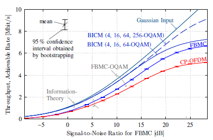
Figure 13. Throughput levels
Filter Bank MultiCarrier, or FBMC, is a multi-carrier modulation technique that has its roots in OFDM. It's a variant of OFDM that seeks to address some of the problems, but at the expense of increased signal processing. FBMC makes better use of usable channel capacity and can provide greater bandwidth within the same given radio spectrum range, resulting in higher spectrum performance. The bit error probability is represented in Figure 12. The error probability of the proposed model is low when compared to traditional models.
The Throughput of the proposed model is depicted in Figure 13. Bits per second (bit/s or bps) is the most common unit of measurement, but data packets per second (p/s or pps) or data packets per time slot are also used. The number of the data rates transmitted to all terminals in a network is known as machine throughput or aggregate throughput. The throughput of the proposed model is high when compared to the traditional methods.
To transmit a real channel, it is important to present an equalizer at the beneficiary info. Another equalizer plan model is proposed by utilizing a FBMC channel to linearize around the period of the evened out channel. The FBMC combined with the merging of the massive MIMO and number of advantages the FBMC offers the application in the 5G communications. The simulation results depict that proposed method is effective. Here the paper analysis for the better PSD for the given spectrums with applying the minimum transmitted power. When rough approximate channel state information is taken into account, simulation results show that FBMC can deliver the highest channel capability and achieve far more performance benefit in our scenarios. The higher spectral efficiency can be achieved for the given spectrum value of the selective channels. The non contiguous form is the subsequent stage, as non-uniform adjustment is a decent way to accomplish more prominent proficiency. Modulation plans with more prominent bit rate is utilized for channels having less noise. In this manner utilizing the information on the channel noise minimal measure of information is transmitted using the channel with most control. For improved connectivity, future 5G networks would need more frequency resources. Since we've been dealing with a problem of frequency shortage, this criterion becomes much more important. Traditional spectrum management policies, on the other hand, leave a significant number of frequency bands underutilised much of the time. Furthermore, further research is required to better understand the issues with FBMC systems' synchronisation, equalisation, and monitoring of channel variations. A possible use of FBMC in the evolving field of massive MIMO was also discussed, along with a number of benefits that FBMC provides in this application.
[1] Marzetta, T.L. (2010). Noncooperative cellular wireless with unlimited numbers of base station antennas. IEEE Transactions on Wireless Communications, 9(11): 3590-3600. https://doi.org/10.1109/TWC.2010.092810.091092
[2] Kim, K.J., Choi, K.J., Lee, S.R., Kim, K.S. (2015). Multi-user massive MIMO for next-generation WLAN systems. Electronics Letters, 51(10): 792-794.
[3] Lu, L., Li, G.Y., Swindlehurst, A.L., Ashikhmin, A., Zhang, R. (2014). An overview of massive MIMO: Benefits and challenges. IEEE Journal of Selected Topics in Signal Processing, 8(5): 742-758. https://doi.org/10.1109/JSTSP.2014.2317671
[4] Hassan, N., Fernando, X. (2017). Massive MIMO wireless networks: An overview. Electronics, 6(3): 63. https://doi.org/10.3390/electronics6030063
[5] Nyarko, J.K.N., Mbom, C.A. (2018). A performance study of massive MIMO heterogeneous networks with Ricean/Rayleigh fading. Electronics, 7(6): 79. https://doi.org/10.3390/electronics7060079
[6] Dao, H.T., Kim, S. (2018). Pilot power allocation for maximising the sum rate in massive MIMO systems. IET Communications, 12(11): 1367-1372. https://doi.org/10.1049/iet-com.2017.1407
[7] Kong, D., Xia, X.G., Jiang, T. (2016). A differential QAM detection in uplink massive MIMO systems. IEEE Transactions on Wireless Communications, 15(9): 6371-6383. https://doi.org/10.1109/TWC.2016.2583428
[8] Wei, R.Y., Wang, X.J. (2017). Differential 16-qam and 16-apsk for uplink massive mimo systems. IEEE Wireless Communications Letters, 7(2): 170-173. https://doi.org/10.1109/LWC.2017.2763143
[9] Wang, Y., Tian, Z. (2017). Multiple symbol differential detection for noncoherent communications with large-scale antenna arrays. IEEE Wireless Communications Letters, 7(2): 190-193. https://doi.org/10.1109/LWC.2017.2764018
[10] Swindlehurst, A.L., Ayanoglu, E., Heydari, P., Capolino, F. (2014). Millimeter-wave massive MIMO: The next wireless revolution? IEEE Communications Magazine, 52(9): 56-62. https://doi.org/10.1109/MCOM.2014.6894453
[11] Prasad, K.S.V., Hossain, E., Bhargava, V.K. (2017). Energy efficiency in massive MIMO-based 5G networks: Opportunities and challenges. IEEE Wireless Communications, 24(3): 86-94. https://doi.org/10.1109/MWC.2016.1500374WC
[12] Wang, Z., Li, M., Tian, X., Liu, Q. (2017). Iterative hybrid precoder and combiner design for mmWave multiuser MIMO systems. IEEE Communications Letters, 21(7): 1581-1584. 10.1109/LCOMM.2017.2682087
[13] Magueta, R., Castanheira, D., Silva, A., Dinis, R., Gameiro, A. (2016). Hybrid iterative space-time equalization for multi-user mmW massive MIMO systems. IEEE Transactions on Communications, 65(2): 608-620. https://doi.org/10.1109/TCOMM.2016.2632732
[14] Magueta, R., Mendes, V., Castanheira, D., Silva, A., Dinis, R., Gameiro, A. (2017). Iterative multiuser equalization for subconnected hybrid mmWave massive MIMO architecture. Wireless Communications and Mobile Computing, 1-13.
[15] Li, A., Masouros, C. (2016). Hybrid analog-digital millimeter-wave MU-MIMO transmission with virtual path selection. IEEE Communications Letters, 21(2): 438-441. https://doi.org/10.1109/LCOMM.2016.2621741
[16] Cui, W., Qu, D., Jiang, T., Farhang-Boroujeny, B. (2015). Coded auxiliary pilots for channel estimation in FBMC-OQAM systems. IEEE Transactions on Vehicular Technology, 65(5): 2936-2946. https://doi.org/10.1109/TVT.2015.2448659
[17] Fuhrwerk, M., Moghaddamnia, S., Peissig, J. (2017). Scattered pilot-based channel estimation for channel adaptive FBMC-OQAM systems. IEEE Transactions on Wireless Communications, 16(3): 1687-1702. https://doi.org/10.1109/TWC.2017.2651806
[18] Kim, C., Yun, Y.H., Kim, K., Seol, J.Y. (2016). Introduction to QAM-FBMC: From waveform optimization to system design. IEEE Communications Magazine, 54(11): 66-73. https://doi.org/10.1109/MCOM.2016.1600384CM