OPEN ACCESS
Ventilated Façades integrated with photovoltaic panels have become a popular way to improve both the thermal-physical performances of the existing built environment. The increased usage of not-programmable renewable energy sources implies the adoption of energy storage systems to mitigate the mismatch between the power generation and the building’s demand. Aiming at properly integrates a photovoltaic panel and a battery (Lithium based) as a module of an active ventilated façade, the prototype design has been carried out in terms of thermo-fluid dynamics performance. Based on experimental setup, a numerical study of flow through the air cavity of the active ventilated façade has been carried out by the fluid-dynamics Finite Volume code-Ansys-Fluent. The calibrated model was lastly used to perform a wide range of parametric analyses on different climate and boundary conditions to explore the viability of the prototype.
BIPV, battery, ventilated façade, CFD
The increase of energy efficiency within the building sector is a major focus of several policy and research actions at international level [1]. Within this area of research, one of the most relevant steps towards improving the energy performance of buildings is the construction of net-zero energy buildings or high-efficiency buildings in the massive use of renewable energies to achieve a higher level of self-sufficiency. Advancing energy efficiency in buildings involves not only the development of new buildings but also retrofitting solutions in the existing building stock.
A number of measures can be taken to enhance building’s performance such as employing advanced building materials, adding insulation layers and improving the envelope structure [2]. External thermal insulation for the retrofit of existing building envelopes can be obtained in two ways [3]: External Thermal Insulation Composite System (ETICS) and Ventilated Façades.
Ventilated Façades integrated with Photovoltaic (PV) cells have become a popular way of the Building Integrated Photovoltaic (BIPV) system to improve both the thermal-physical performances of the existing built environment [4-5] and PV conversion efficiency. PV panels shading the building reduce heat gain from solar radiation and the air cavity has a beneficial effect on the PV temperature: in fact, facilitating the buoyancy force resulted from the solar radiation, the ambient air is induced into the channel from the bottom and discharged at the top. High temperature of the PV module has negative influence on its efficiency [6].
The increased usage of not-programmable renewable energy sources implies the adoption of energy storage systems to mitigate the mismatch between the power generation and the building’s demand [7-9]. Integrating a PV panel with batteries as a whole system is an attracting solution [10], but the battery must be kept at the proper working temperature to avoid damages and accelerated degradation [11-12].
Aiming at properly integrates a photovoltaic panel and a battery (Lithium based) the thermo-fluid dynamics performance of the integrated module of an active ventilated façade, has been assessed.
The geometry and dimensions of the air gap are the keys to predict the overall performance of the BIPV and their design is complex depending, e.g., on the amount of solar radiation falling on façade, variation of the ambient temperature and wind speed.
Ventilated façades and the effects of the air gap behind PV wall (including battery and electronic boards) on heat transfer and ventilation has been studied theoretically and experimentally.
In literature CFD approach was utilized as the main method to achieve accurate and detailed results for modeling the temperature and airflow distributions.
Sandberg and Moshfegh, [7] performed CFD simulations to derive temperature and velocity profiles in air gaps behind solar cells located on vertical facades. Both the geometry of the air gap and the location of the solar cell module are varied. Analytically expressions for the mass flow rate, velocity, temperature rise and location of neutral height (location where the pressure in the air gap is equal to the ambient pressure) were also obtained.
Guohui Gan [14] performed CFD simulations of buoyancy-induced flow in open cavities for natural ventilation. The effect of the cavity width of solar chimneys and double façades on the buoyancy-induced ventilation rate was investigated. It was found that there existed an optimum cavity width for maximising the buoyancy-induced flow rate. The ventilation rate in a double façade of four-storeys high generally increased with cavity width but decreased with floor level from bottom to top.
Peng et al. [9] evaluated the overall performance of ventilated PV façade under different ventilation strategies. The tested results showed that the ventilated mode performed better for improving the electricity output and reducing the solar heat gain.
Aim of this work is to assess the effectiveness of the peculiar design of ventilative façade proposed in the paper through Computational fluid dynamics (CFD) simulations in steady state conditions. The design includes a PV system as external façade and some electronic components within the air cavity, which should both enhance the thermal stack effect, as well as have a better management of excess heat.
The model has been calibrated on experimental data. Temperature profiles in air gaps with and without the heat sources have been derived.
A numerical model was developed to investigate the airflow and temperature distributions of a ventilated façade based on the experiments carried out at CNR-ITAE.
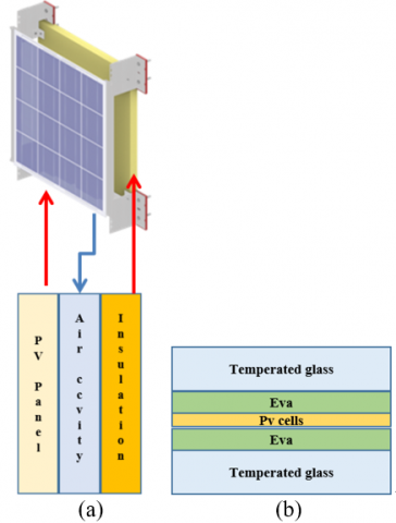
The numerical model was implemented in the multi-physics Finite Volume Code Ansys Fluent. The simulated prototype consists of a PV panel mounted above a layer of insulation separated by an air channel. A heat source (battery and dc/dc) has been simulated within the air cavity.
A schematic of the model is shown in Figure 1(a).
The PV panel used in the performed module consists of a lower sheet of tempered prismatic glass (dimensions 680 x 680 mm x 3 mm), a layer of EVA 0.5 mm (vinyl acetate that undergoes temperature turns into inert adhesive), matrix of photovoltaic cells 0.2 mm, a layer of EVA0.5 mm and a sheet of tempered prismatic glass dimensions 680×680 mm×3 mm. A schematic of the PV's layers is shown in Figure 1 (b).
The air channel thickness is 20 cm [10]. On the other side of the air channel, typical construction materials made up the wall. The EVA and the PV cells are thin (compared with other computational domains) so the temperature difference across the EVA and PV cells is negligible. Therefore, the EVA sheets and PV cells are treated as a single domain for the heat transfer simulation. A similar approach was used by Nizetic et al. [11].
Fixed on the insulation there are two casings 18 cm×14 cm×4 cm containing a battery, an integrated MPPT and bidirectional battery charger (dc/dc). The battery 116 mm×106 mm×22 mm has nominal capacity 23 Ah and nominal voltage 2.3 V. The diode (Shottky), consisting of metal-semiconductor junctions, has a slope resistance r 8.8 mΩ. The battery and the diode are available on the market and the data is reported in the manufacturers’ datasheets. The casings are closed to protect the battery and the electrodes of the diode from dust and moisture. As a result, generated heat by Joule effect is not well dissipated. Since both battery and diode dissipate heat is important to assess whether the surface temperatures reached are compatible with the maximum temperatures that can be combined with the materials of which the casing is made.
Figure 1. (a) Schematic of the model and (b) schematic of the PV panel layers
In Table 1 e Table 2 each material physical properties including density ρ, thermal conductivity λ and specific heat capacity (Cp) are specified [12].
Table 1. Properties of PV module layers
|
Property |
Glass |
Silicon cells |
Eva |
|
ρ (kg/m3) |
2500 |
2330 |
935 |
|
Cp (J/(kg K) |
750 |
700 |
2500 |
|
λ (W/(m K)) |
1.04 |
150 |
0.29 |
Table 2. Properties of Box and Insulation materials
|
Property |
Polypropylene |
Stone wool |
|
ρ (kg/m3) |
1030 |
100 |
|
Cp (J/(kg K) |
1400 |
1030 |
|
λ (W/(m K)) |
0.16 |
0.035 |
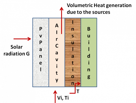
Utilizing these dimensions and properties a numerical 2D model was created with temperature dependent air properties. The boundary conditions on the outside of the PV panel included the measured solar radiation as a heat flux and convective heat transfer due to the wind. Volumetric heat absorption was applied to the PV cells layer. A similar approach was used by in [19]. Volumetric heat generation was applied to the heat sources (casings) within the air cavity. In the inner wall a convective condition is imposed. The external surface of the insulation was fixed at T = 26 °C.
The thickness of the PV panel (7 mm) is small relative to his width and height (680 mm×680 mm) so it’s reasonable to assume that conduction occurs exclusively in the direction orthogonal to the surface of the panel. In this study the radiative heat transfer is neglected [20].
The air velocity and the air temperature were measured experimentally and used as inputs for the air inlet in the model. The air velocity and direction have a random character so it is not easy to predict its action. To design the wind effects the mean values for velocity and direction are used.
For the air outlet a pressure outlet boundary condition was imposed because outlet was provided to be free flow. A schematic of the boundary conditions is shown in Figure 2.
Figure 2. Schematic of the boundary conditions
To estimate the volumetric heat dissipation of the dc-dc ($q_d$) and battery $q_b$ have been made the following assumptions:
$q_d=(1-η_d)P_{pv}$ (1)
$q_b=(η_d)(1-q_b)P_{pv}$ (2)
where $P_{pv}$ is the power of the PV panel (W), $η_d$ and $η_b$ are the efficiency of the diode and battery, respectively.
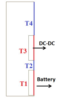
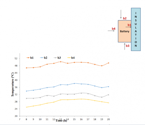
To investigate the effects of the heat sources on the insulation the inner insulation has been divided in four zones as shown in Figure 3.
Figure 3. Schematic of the thermal zones of the insulation
2.1 Mathematical model
The mathematical model for the prototype described in this paper can be divided into three main parts: electrical model fluid model and heat transfer model.
2.1.1 Electrical model
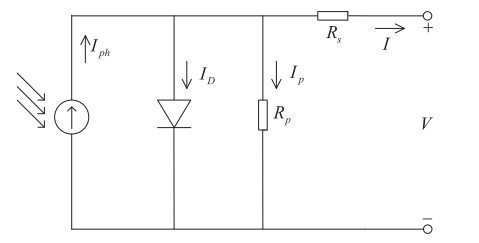
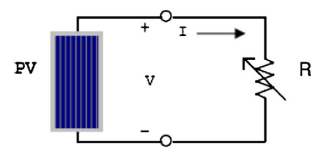
It is known that a solar cell is represented by an equivalent circuit composed of a current source, an anti-parallel diode (D), a shunt/parallel resistance (Rp) and a series resistance (Rs). A schematic equivalent circuit is shown in Figure 4.
It is widely acknowledged that the photovoltaic generator is neither a costant voltage source nor a current source.
The photovoltaic generator is modeled by the relationship between current and voltage. Based on the Shockley diode equation I is as followed [15]:
$I=I_{ph}-I_0(e^{\frac{V+IR_s}{V_t}}-1)-\frac{V+IR_s}{R_p}$ (3)
where $I_ph$ is the photo current (A), $I_0$ is the diode saturation current (A), $R_s$ is the series resistance (Ω), $R_p$ is the shunt/parallel resistance (Ω), $V_t$ is the diode thermal voltage (V).
Figure 4. Equivalent circuit for a solar cell [15]
An example of I-V and P-V curves are shown in Figure 5.
Figure 5. An example of the I-V and P-V curves [15]
When a PV module is directly coupled to a load, as shown in Figure 8, the PV module's operating point will be at the intersection of its I–V curve and the load line which is the I–V relationship of load In general, the optimal intersection occurs at one particular operating point, called Maximum Power Point (MPP). The location of the MPP in the I–V plane changes dynamically depending on irradiance and temperature [14]. In order to optimize a BIPV power generation the adoption of a distributed MPPT approach, using a dc-dc converter per each panel, is suggested in literature overcoming major drawbacks due to the effect of module mismatching and of partial shading of the BIPVs.
Figure 6. PV coupled to a load [16]
2.1.2 Fluid model
Based on two-dimensional space rectangular coordinate system, the momentum equation, i.e., Navier-Stokes equation, is as followed:
$u_x\frac{\partial u_x}{\partial x}+u_y\frac{\partial u_y}{\partial y}=v(\frac{\partial^2 u_x}{\partial x^2}+\frac{\partial^2 u_x}{\partial x^2})-\frac{1}{ρ}\frac{\partial P}{\partial x}$ (4)
$u_x\frac{\partial u_x}{\partial x}+u_y\frac{\partial u_y}{\partial y}=v(\frac{\partial^2 u_x}{\partial x^2}+\frac{\partial^2 u_x}{\partial x^2})-\frac{1}{ρ}\frac{\partial P}{\partial y}-g$ (5)
where ρ is the fluid density (kg/m3), $u_x$ and $u_y$ are the x-velocity and the y-velocity (m/s), v is coefficient of kinematic viscosity (N s / m2), g is the gravity acceleration (kg m/s2).
2.1.3 Heat transfer model
The heat transfer is a consequence of the solar radiation on the PV modules is partly reflected by the tempered glass layers and partly absorbed by the solar cell layers. The solar energy absorbed by the solar cells is partly converted into direct current (DC) electricity and the absorbed remainder is dissipated as waste heat increasing operating temperature for the PV module. Higher temperature of unit has negative influence on PV panel's efficiency [6].
The energy balance equations are as followed [17-18]:
$u_x\frac{\partial T}{\partial x}+u_y\frac{\partial T}{\partial y}=\frac{λ}{ρC_p}(\frac{\partial^2 T}{\partial x^2}+\frac{\partial^2 T}{\partial y^2})$ (6)
where λ is the thermal conductivity of each part (W/(m K) and Cp is the specific heat of each part (J/(Kg K)).
The waste heat stemming from the solar cell layers is conducted within the front and back tempered glass layers.
In the air cavity the heat exchange with the back side tempered glass layer of the PV panel and the front side of the insulation is dominated by the conductive and radiative heat transfer. At the front and back surface the energy balance equations are the following [17,18]:
$\begin{cases} ρC_pdx\frac{\partial T}{\partial t}=α_{glass}G_{PV}A(1-η)-q^{rad}_{front}+q^{conv}_{front}\\ q^{rad}_{front}=\varepsilon _{glass}F\sigma(T^4_{sur}-T^4_{sky})\\ q^{conv}_{front}=h(T_{sur}-T_{amb}) \end{cases}$ (7)
$\begin{cases} ρC_pdx\frac{\partial T}{\partial t}=q^{rad}_{front}+q^{conv}_{front}\\ q^{rad}_{front}=\varepsilon _{glass}F\sigma(T^4_{back}-T^4_{groud})\\ q^{conv}_{front}=h(T_{back}-T_{amb}) \end{cases}$ (8)
where $α_{glass}$ is the absorptivity of the glass, $G_{PV}$ is the solar radiation on the PV module (W/m2), η is the efficiency of the PV panel (%), $q_{front}^{rad}$e$q_{front}^{conv}$ are the radiative and convective heat flux at the front of the PV (W/m2), $q^{rad}_{back}$ and $q^{conv}_{back}$ are the radiative and convective heat flux at the back of the PV (W/m2), $ε_{glass}$ is the emissivity of the glass, F is the view factor of PV surface, σ is the Stefan-Boltzmann constant, h is the natural convective rate (W/(m2K)), $T_{sur}$, $T_{sky}$, $T_{back}$, $T_{ground}$ and $T_{amb}$ are respectively the temperature of the front surface, the sky, the back surface, the ground and ambient temperature (°C). In this study α is set as 0.9 [19] and as 14 %.
The net solar radiation on PV front surface is given by:
$Q=α_{glass}G_{PV}A$ (9)
where A is the area of the PV panel (m2).
The part of the energy that is converted in heat is given by:
$Q=α_{glass}G_{PV}A(1-η)$ (10)
h is given by [19]:
$f_{free}=\frac{λ}{L}\{0.825+\frac{0.387Ra^{1/6}_L}{[1+(0.492/Pr)^{9/16}]^{8/27}}\}^2$ (11)
$h_{forced}=\frac{λ}{L}(0.664Re^{1/2}{L}Pr^{1/3})$ (12)
where L is the height of PV panel (m), $R_{aL}$ is the Raleigh number, $R_{eL}$ is the Reynolds number and Pr is the Prandtl number.
$Re=\frac{ul}{v}$ (13)
$Pr=\frac{v}{α}$ (14)
where α is the thermal diffusivity (N s / m2)
$Ra_L=\frac{gβΔTL^3}{αv}$ (15)
where β is the thermal expansion coefficient (1/K), ΔT is the temperature difference between PV and insulation.
In the Fluent solver, RNG k-$\varepsilon$ model was selected in the Viscous Model and Enhanced Thermal Treatment was active in near-wall treatment. Environmental atmospheric pressure was defined as standard atmospheric pressure. Coupled algorithm was used in pressure-velocity coupling equation. Second Order Upwind was selected in momentum and energy equations. The simulations have been conducted in steady state conditions.
2.2 Lab test
Experimental tests have been performed in CNR-ITAE in Messina (Italy).
To evaluate the producibility of two distinct photovoltaic cell technologies that can be integrated into the hybrid module (PV / insulation / batteries) to cover the perimeter walls of a building the panels have been tested.
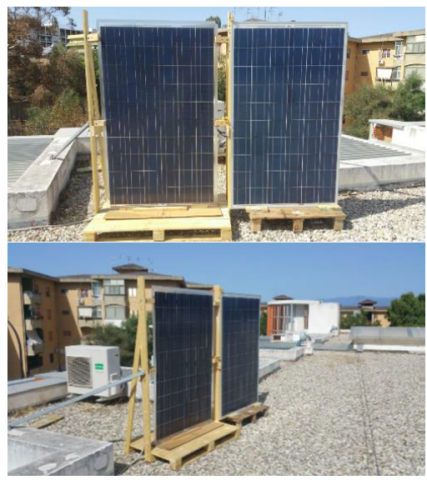
The two panels, one in polycrystalline silicon with a metal frame and the other one in polycrystalline silicon with a double staggered glass, were arranged vertically as shown in Figure 7.
Figure 7. Installated PV panels to carry out producibilty measurements in a vertical plane
To carry out the characterization measurements, the panels were connected to the terminals of the low impedance circuit of an electronic direct current load (Chroma 63640-80-80, in Figure 2), consisting of 5 modules (400W per module).
The light radiation was measured on the plane of the modules through a calibrated photovoltaic cell. The global radiation (G) was measured through the pyranometer of a weather station located a short distance from the panels, but raised to avoid the shadowing of obstacles on the plane of the panels under test. In parallel, air temperatures were measured near the modules, and on the rear panel of each module.
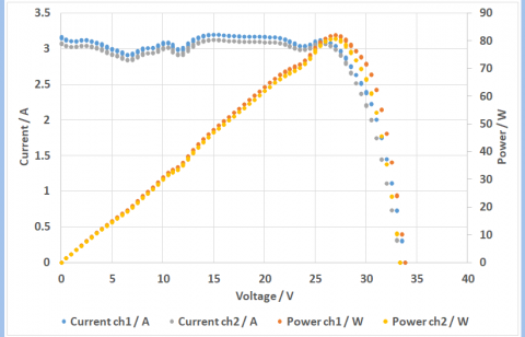
The test was conducted in galvanostatic control mode with voltage scans in 0.5 V steps every 2 seconds (with 2 Hz sampling) from 34 V to 0 V. The maximum voltage, although lower than the theoretical OCV, was in any case sufficient (due to the vertical inclination of the photovoltaic modules) to measure zero current. For each iterated cycle, peak power was detected. In Figure 8 is shown the production from PV modules in vertical installation when G is 265 (W/m2). Experimental data have been measured every two minutes, the entire experimental test has a total time of three hours, the inputs of the simulations are the average values estimated every ten minutes.
Figure 8. Production from PV modules in vertical installation when G is 265 (W/m2)
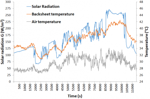
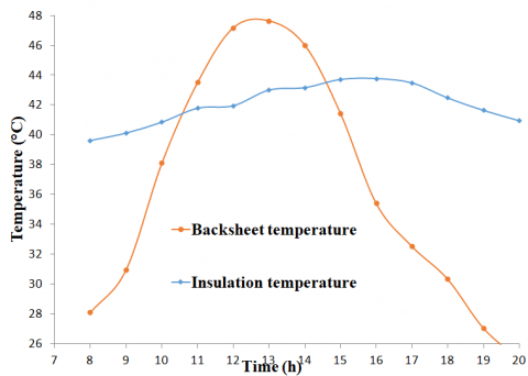
As previously mentioned, the temperature of the rear side of the PV was measured during the tests and the temperature of the backsheet was simulated based on the mathematical model provided in 2.1.3 to evaluate its thermal performance.
In Figure 9 are shown the solar radiation and the temperatures profiles evaluated during the tests.
Figure 9. Hourly profiles of the air and backsheet temperature and solar radiation
2.3 Model validation
The free convection of the PV panel without cavity to predict the temperature profile of the backside of the PV panel was simulated. Experimental data solar radiation, air temperature and air velocity were used as boundary conditions in the numerical model.
To avoid the mesh dependency program, a grid sensitive test was conducted and a mesh of about 130,000 elements has been used for the simulations. Increasing the number of elements will provide a more accurate solution but will also increase the computation resources required.
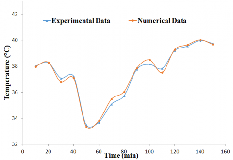
Figure 10 shows a comparison between the numerical results and the experimental data during a test of about three hours. The simulations were conducted in steady state conditions. Inputs data are the experimental data average every ten minutes. Overall the numerical data showed a good agreement with the experimental ones.
Figure 10. Comparison between experimental and numerical data of the backsheet temperature of the PV panel
2.4 Results and discussion
Utilizing experimental data mentioned above, the air channel between the BV panel and the insulation was simulated layer to predict the temperature profile of the insulation without the heat sources. The temperature difference between PV and insulation generates buoyancy to push up the channel air and remove part of the heat by natural convection. A part of the heat energy will be transmitted into the indoor space by means of thermal conduction through the wall of the building. The outdoor air can flow into the air cavity generating force convection and removing the heat both the PV and the insulation. A mixed convection mechanism is generated within the air cavity. The results showed an increase of the backsheet temperature less than 1 °C. The PV panel simulated has a Voltage coefficient = 122 mV/°C and a Current coefficient = 4.36 mA/°C so the reduction of the efficiency of the PV panel is neglected.
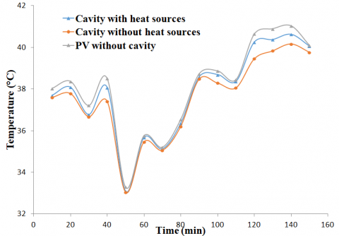
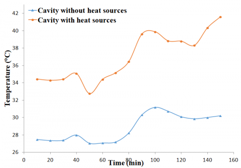
In order to evaluate the effect inducted by the battery and the electronics due the heat generated the system has been simulated also taking it into account. The results show that an increase in both the backsheet temperature and insulation temperature in respect of the previous case. Figure 11 shows a comparison of the thermal profile of the backsheet without cavity, with cavity without heat sources and with cavity and heat sources. shows the thermal profile of the average temperature of the insulation with and without heat sources in the air cavity. The presence of the heat sources leads to a restriction in the convective heat exchange causing an increase in the temperature both the backsheet and the insulation. It is worth noting that, as expected, front surface temperature of the insulation increase in the area corresponding to the back side of the casings as shown in Figure 12.
Figure 11. Backsheet temperature of the PV panel without cavity, with cavity without heat sources and with cavity and heat sources
Figure 12. Insulation average temperature in the air cavity with and without the heat sources
In order to assess the temperature profiles along an entire day, a simulation has been run from 8:00 AM to 8:00 PM of 20th June 2018. The data have been logged by a weather station located at CNR-ITAE.
Table 3. Data logged by a weather station located at CNR-ITAE
|
Time (hours) |
Air Temp [°C] |
Vertical Solar radiation [W/mq] |
|
8:00 AM |
22.35 |
73.01 |
|
9:00 AM |
23.00 |
101.37 |
|
10:00 AM |
23.65 |
183.24 |
|
11:00 AM |
24.40 |
244.26 |
|
12:00 AM |
25.20 |
274.15 |
|
1:00 PM |
26.00 |
274.51 |
|
2:00 PM |
26.50 |
243.59 |
|
3:00 PM |
26.70 |
187.16 |
|
4:00 PM |
26.90 |
107.72 |
|
5:00 PM |
26.65 |
75.64 |
|
6:00 PM |
26.00 |
53.53 |
|
7:00 PM |
25.35 |
21.07 |
|
8:00 PM |
24.85 |
1.30 |
The assessment allows checking the temperatures throughout the system and in particular on the battery casing, results are reported in Figure 13 e Figure 14.
Comparing the data provided by the manufacturers the maximum temperature admitted by the diode (150 °C) is much higher than that of the battery (60 °C) so it’s crucial to fix the casings to facilitate the cooling of the battery.
Figure 13. Thermal profiles during an entire day (from 8:00 AM to 8:00 PM)
Figure 14. Surface temperature of the casing containing the battery during an entire day (from 8:00 AM to 8:00 PM)
The model consists of a photovoltaic panel, a layer of insulation, the air cavity between the panel and insulation and two heat sources fixed on insulation.
The solar radiation is a dominant factor because causing heat generation in the cells affects the cell temperature. In particular, results showed that, an overage, every 100 W/m2 increase in solar radiation caused an increase of about 5 °C in photovoltaic panel temperature. Also the wind velocity is a crucial factor on the natural ventilation cooling. The simulations were conducted varying both solar radiation and wind velocity so it was more complex to establish the dependence of the thermal profiles by the wind effects. The heat sources (battery and electronic boards) overheat the air cavity causing an increase of 2°C-5°C in the backsheet temperature and 5°C-10°C on the insulation.
A future study will carry out to investigate the effect of air gap depth on the photovoltaic panel performance in terms of temperature and heat removal.
The study has been supported by the Ministry of Economic Development - Fund for sustainable growth (HORIZON 2020) - Project no. 181 “e-brick”.
[1] Papadopoulos AM. (2016). Forty years of regulations on the thermal performance of the building envelope in Europe: Achievements, perspectives and challenges. Energy Buildings 127: 942-952.
[2] Sozer H. (2010). Improving energy efficiency through the design of the building envelope. Building & Environment 45: 2581-2593. https://doi.org/10.1016/j.buildenv.2010.05.004
[3] Colinart T, Bendouma M, Glouannec P. (2019). Building renovation with prefabricated ventilated façade element: A case study. Energy Buildings 186: 221-229. https://doi.org/10.1016/J.ENBUILD.2019.01.033
[4] Lai CM, Hokoi S. (2015). Solar façades: A review. Building & Environment 91: 152-165. https://doi.org/10.1016/j.buildenv.2015.01.007
[5] Zhang T, Tan Y, Yang H, Zhang X. (2016). The application of air layers in building envelopes: A review. Applied Energy 165: 707-734. https://doi.org/10.1016/J.APENERGY.2015.12.108
[6] Dubey S, Sarvaiya JN, Seshadri B. (2013). Temperature dependent photovoltaic (PV) efficiency and its effect on PV production in the world. Energy Procedia 33(2013): 311-321. https://doi.org/10.1016/j.egypro.2013.05.072
[7] Sandberg M, Moshfegh B. (2002). Buoyancy-induced air flow in photovoltaic facades: Effect of geometry of the air gap and location of solar cell modules. Building & Environment 37: 211-218. https://doi.org/10.1016/S0360-1323(01)00025-7
[8] Gan G. (2006). Simulation of buoyancy-induced flow in open cavities for natural ventilation. Energy Buildings 38: 410-420. https://doi.org/10.1016/J.ENBUILD.2005.08.002
[9] Peng J, Lu L, Yang H, Ma T. (2015). Comparative study of the thermal and power performances of a semi-transparent photovoltaic façade under different ventilation modes. Applied Energy 138: 572-583. https://doi.org/10.1016/j.apenergy.2014.10.003
[10] Zhang R, Mirzaei PA, Carmeliet J. (2017). Prediction of the surface temperature of building-integrated photovoltaics: Development of a high accuracy correlation using computational fluid dynamics. Solar Energy 147: 151-163. https://doi.org/10.1016/j.solener.2017.03.023
[11] Nižetić S, Grubišić-Čabo F, Marinić-Kragić I, Papadopoulos AM. (2016). Experimental and numerical investigation of a backside convective cooling mechanism on photovoltaic panels. Energy 111: 211-225.
[12] Ma T, Zhao J, Li Z. (2018). Mathematical modelling and sensitivity analysis of solar photovoltaic panel integrated with phase change material. Applied Energy 228: 1147-1158. https://doi.org/10.1016/j.apenergy.2018.06.145
[13] Roeleveld D, Hailu G, Fung AS, Naylor D, Yang T, Athienitis AK. (2015). Validation of Computational Fluid Dynamics (CFD) Model of a Building Integrated Photovoltaic/Thermal (BIPV/T) System. Energy Procedia 78: 1901-1906. https://doi.org/10.1016/j.egypro.2015.11.359
[14] Algazar MM, AL-monier H, EL-halim HA, Salem MEEK. (2012). Maximum power point tracking using fuzzy logic control. Journal of Electrical Power & Energy Systems 39: 21-28. https://doi.org/10.1016/J.IJEPES.2011.12.006
[15] Ma T, Yang H, Gu W, Li Z, Yan S. (2019). Development of walkable photovoltaic floor tiles used for pavement. Energy Conversion and Management 183: 764-771. https://doi.org/10.1016/j.enconman.2019.01.035
[16] Akihiro O. (2005). Design and simulation of photovoltaic water pumping system.
[17] Ma T, Yang H, Lu L. (2014). Development of a model to simulate the performance characteristics of crystalline silicon photovoltaic modules/strings/arrays. Solar Energy 100: 31-41.
[18] Singh GK. (2013). Solar power generation by PV (photovoltaic) technology: A review. Energy 53: 1-13.
[19] Kant K, Shukla A, Sharma A, Biwole PH. (2016). Heat transfer studies of photovoltaic panel coupled with phase change material. Solar Energy 140: 151-161. https://doi.org/10.1016/j.solener.2016.11.006