Cuixia Wei* | Yipeng Jia | Qingang Liu | Haifeng Yu
© 2020 IIETA. This article is published by IIETA and is licensed under the CC BY 4.0 license (http://creativecommons.org/licenses/by/4.0/).
OPEN ACCESS
This paper attempts to determine the reasonable height of Vierendeel truss. For this purpose, both analytical and finite-element methods were adopted to investigate how the structural height affects stiffness and global stability. The results show that the structural stiffness of Vierendeel truss varied significantly with the height, peaking at the reasonable height; the global stability changed slowly with the height. On this basis, the authors put forward the formula of reasonable height for engineering design of Vierendeel truss. The results provide a reference for designers to optimize the stiffness and stability of Vierendeel truss.
Vierendeel truss, stiffness, global stability, reasonable height
The Vierendeel truss is a popular structure in the transfer floor of large-span and high-rise buildings requiring the opening of doors and windows. The popularity arises from the elimination of diagonal web member, which allows full utilization of the structural space. The Vierendeel truss has many different forms, such as equal-space Vierendeel truss, unequal-space Vierendeel truss, laminated Vierendeel truss, and staggered Vierendeel truss. Moreover, several Vierendeel trusses can be arranged in two or three directions to form a Vierendeel grid, a high-stiffness structure widely used in large-span and high-rise buildings.
Since its invention by Jules Arthur Vierendeel in late 19th century, the Vierendeel truss has been extensively explored by researchers. Korol et al. [1] examined unequal width joints of square hollow sections in Vierendeel trusses, and presented a stiffness-based analysis method for Vierendeel trusses comprised of such joints. Later, Shehata et al. [2] carried out an inelastic finite-element analysis of Vierendeel trusses of rectangular hollow sections. Basha and Goel [3] presented an alternative configuration of the special truss segment for special truss moment frames. Dai et al. [4] applied laminated Vierendeel truss in the transfer floor of tall buildings, revealing the excellent seismic behaviors of the laminated Vierendeel trusses with prestressed concrete and shape steel concrete. Kim et al. [5] designed staggered truss systems (STS), and evaluated their seismic performances through pushover analysis. Hameed and Mahmod [6] investigated the application of fiber-reinforced concrete in the construction of Vierendeel trusses with nonlinear material behavior. Machacek and Cudejko [7] probed into the longitudinal shear in composite steel and concrete trusses. Luo et al. analyzed the nodal strength of pipe-plate and tube-plate Vierendeel trusses, and put forward the formulas of nodal ultimate bearing capacity [8, 9]. Zhang et al. implemented the Vierendeel trusses in innovation of old buildings, and provided a very efficient alternative to overcome large span: a composite hollow Vierendeel truss [10, 11].
Guo et al. [12] proposed the prediction equations for global in-plane elastic buckling, global in-plane ultimate strength, and chord local strength of the Vierendeel truss arch. Ameer et al. [13] tested the structural behavior of Vierendeel truss in replacement of bearing wall in precast construction. Kong et al. [14] tackled the seismic resistance of intersection joints of Vierendeel truss with column in weak-axis in steel grid cassette structures. Nimnim and Shaaban [15] analyzed the effect of concrete strength on the flexural behavior of Vierendeel steel and concrete composite beams. Based on Allftlish’s theory of Vierendeel truss, Jiang et al. [16] created a new simplified calculation method, and relied on the method to analyze the internal force and deformation of Vierendeel beam with three kinds of joints. In a government-sponsored design contest, the contestants invented the Vierendeel structural system for the North Frame Pedestrian Bridge [17]. Hassan et al. conducted experiments on the behavior of Vierendeel truss in lieu of bearing wall in precast construction, and performed three-dimensional (3D) static and dynamic analyses for steel pedestrian Vierendeel bridges [18, 19]. Drawing on the previous literature, Pons Poblet [20] introduced the main features and calculation methods of Vierendeel truss, as well as its implementation in civil engineering and architectural works.
To sum up, the existing research on Vierendeel truss mainly focuses on calculation method, and mechanical properties. However, there is little report on the stiffness and safety of Vierendeel truss, two important properties of such a large-span spatial structure. Due to the lack of theoretical basis, the geometric parameters and structure design of Vierendeel truss have been largely empirical, failing to maximize the stiffness and global stability of the structure. This will surely lead to material waste and cost hike. To improve the practical design of Vierendeel truss, it is particularly important to select reasonable geometric parameters at the beginning of the design, laying the basis for the optimization of structural stiffness and global stability and the improvement of design efficiency.
This paper explores how structural height affects the stiffness and global stability of Vierendeel truss with the analytical method and the finite element method, respectively. On this basis, the reasonable height of Vierendeel truss was determined for engineering design.
According to the principle of equivalent stiffness, the Vierendeel truss with five or more grids is equivalent to a solid web girder. In terms of composition, each Vierendeel truss member is a beam unit with fewer intersections with the bar and under more complex stress. The structure might suffer from bending and shear deformations, but stays immune to axial or distortion deformations. The structural height h, bending stiffness EI, and shear stiffness C of the Vierendeel truss are the same as those of solid web girder.
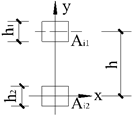
Figure 1 shows a Vierendeel truss and its typical internode i (size: ai×h). Figure 2 presents the solid web girder with equivalent stiffness and its typical element (size: ai×h) corresponding to the typical internode of the truss. Note that Ai1 and Ai2 are the sectional areas of upper and down chords in section i, respectively; Iiv1 and Iiv2 are the moments of inertia of left and right vertical members in section i, respectively.
Figure 1. The Vierendeel truss and its typical internode
Figure 2. The solid web girder and its typical element
Following the equivalence principle, a unit bending moment was applied on both ends of the typical internode of the Vierendeel truss and the typical element of the solid web girder, creating the same angle. Since the two objects have the same material and angle, their bending stiffnesses and the section moments of inertia must be the same. Let I1 and I be the section moment of inertias of the typical internode and the typical element, respectively. Then, the coordinate system for the typical internode can be established as shown in Figure 3, where $\bar{y}=\frac{A_{\mathrm{i} 1} \times h}{A_{i 1}+A_{i 2}}$ is the section centroid.
Figure 3. The coordinate system for the typical internode
Then, the section moment of inertia for the typical internode can be deduced by:
${{I}^{1}}=\frac{{{b}_{\text{i}1}}{{h}_{1}}^{3}}{12}+{{\left( h-\overline{y} \right)}^{2}}\times {{A}_{\text{i}1}}+\frac{{{b}_{\text{i}2}}{{h}_{2}}^{3}}{12}+{{\left( \overline{y} \right)}^{2}}\times {{A}_{\text{i}2}}$${{I}^{1}}=\frac{{{b}_{\text{i}1}}{{h}_{1}}^{3}}{12}+{{\left( h-\overline{y} \right)}^{2}}\times {{A}_{\text{i}1}}+\frac{{{b}_{\text{i}2}}{{h}_{2}}^{3}}{12}+{{\left( \overline{y} \right)}^{2}}\times {{A}_{\text{i}2}}$ (1)
where, bi1 and bi2 are the widths of upper and down chords in section i, respectively; h1 and h2 are the heights of upper and down chords in section i, respectively.
For the Vierendeel truss, h1 and h2 are far smaller than h, and of higher powers. Hence, the first two terms in formula (1) are negligible. Then, formula (1) can be transformed into:
$I={{I}^{1}}=\frac{{{A}_{\text{i}1}}{{A}_{\text{i}2}}}{{{A}_{\text{i}1}}+{{A}_{\text{i2}}}}\times {{h}^{2}}$ (2)
2.2 Equivalent shear stiffness
Following the equivalence principle, a unit shear was applied on both ends of the typical internode and the typical element, creating the same shear angle. On this basis, it is possible to derive the equivalent shear stiffness C. The basic assumptions are as follows: (1) The inflection points of upper chord, lower chord, and vertical member are in the middle; (2) The torsion effect is negligible, and the first power of shear and bending moment is considered only. Figure 4 illustrates the $\bar{M}$ of the typical internode.
Figure 4. The $\bar{M}$ of the typical internode (kN·m)
The shear angle and shear stiffness of the Vierendeel truss can be respectively calculated by:
$r=\frac{F}{C}=\frac{{{\Delta }_{\text{i}}}}{{{a}_{\text{i}}}}={{a}_{\text{i}}}\left( \frac{{{i}_{\text{i}2}}{{i}_{\text{iv}1}}{{i}_{\text{iv}2}}+{{i}_{\text{i1}}}{{i}_{\text{iv}1}}{{i}_{\text{iv}2}}+{{i}_{\text{i1}}}{{i}_{\text{i}2}}{{i}_{\text{iv}2}}+{{i}_{\text{i1}}}{{i}_{\text{i}2}}{{i}_{\text{iv}1}}}{48{{i}_{\text{i1}}}{{i}_{\text{i}2}}{{i}_{\text{iv}1}}{{i}_{\text{iv}2}}} \right)$ (3)
$C=\frac{48{{i}_{\text{i1}}}{{i}_{\text{i}2}}{{i}_{\text{iv}1}}{{i}_{\text{iv}2}}}{{{a}_{\text{i}}}\left( {{i}_{\text{i}2}}{{i}_{\text{iv}1}}{{i}_{\text{iv}2}}+{{i}_{\text{i1}}}{{i}_{\text{iv}1}}{{i}_{\text{iv}2}}+{{i}_{\text{i1}}}{{i}_{\text{i}2}}{{i}_{\text{iv}2}}+{{i}_{\text{i1}}}{{i}_{\text{i}2}}{{i}_{\text{iv}1}} \right)}$ (4)
where, ii1 and ii2 are the linear stiffnesses of upper and lower chords, respectively; iiv1 and iiv2 are the linear stiffnesses of left and right vertical members, respectively.
According to the principle of equivalent stiffness, an equivalent solid web girder was designed for the Vierendeel truss. The equivalent solid web girder could be affected by bending moment and shear, but not by axial force. Then, the deformation of solid web girder under vertical load can be described as:
$f=\int{\frac{\overline{M}{{M}_{P}}}{EI}}ds+\int{k\frac{\overline{{{F}_{Q}}}{{F}_{QP}}}{C}}ds$ (5)
where, m and n are equal to $\int \bar{M} M_{p} d s$ and $\int \overline{F_{Q}} F_{Q P} d s$, respectively. Both depend on the vertical load, regardless of the structure. The values of m an n can be derived through graph multiplication in structural mechanics. Focusing on structural stiffness, this paper ignores the influence of load change. Substituting formulas (2) and (4) into formula (5):
$f=\sum\limits_{i=1}^{R}{\left[ \frac{{{m}_{\text{i}}}}{{{E}_{\text{i}}}}\left( \frac{1}{{{A}_{\text{i}1}}}+\frac{1}{{{A}_{\text{i}2}}} \right)\times \frac{1}{{{h}^{2}}} \right]+\sum\limits_{i=1}^{R}{\left\{ \left[ \frac{k{{n}_{\text{i}}}}{48{{E}_{\text{i}}}}\left( \frac{1}{{{I}_{\text{iv}}}_{1}}+\frac{1}{{{I}_{\text{iv}}}_{2}} \right)\times {{a}_{\text{i}}}\times h+\frac{k{{n}_{\text{i}}}}{48{{E}_{\text{i}}}}\left( \frac{1}{{{I}_{\text{i}}}_{1}}+\frac{1}{{{I}_{\text{i}2}}} \right)\times {{a}_{\text{i}}}^{2} \right] \right\}}}$ (6)
where, R and h are the number of internodes and height of the Vierendeel truss, respectively; Ei is the elastic modulus of section i; Ii1 and Ii2 are the moments of inertia of upper and down chords in section i, respectively.
Assuming that the material, internode length and sectional size are constant along the span of the Vierendeel truss, formula (6) can be rewritten as:
$f=\frac{m}{E}\left( \frac{1}{{{A}_{1}}}+\frac{1}{{{A}_{2}}} \right)\frac{1}{{{h}^{2}}}+\left[ \frac{kn}{24E{{I}_{\text{v}}}}ah+\frac{kn}{48E}\left( \frac{1}{{{I}_{1}}}+\frac{1}{{{I}_{2}}} \right){{a}^{2}} \right]$ (7)
As shown in formula (6), the deformation of Vierendeel truss consists of bending deformation and shear deformation; with the growing structural height, the bending deformation decreases like a quadratic curve, while the shear deformation increases linearly. Therefore, there should be a reasonable structural height to maximize the stiffness and minimize the structural deformation.
Taking the derivative of formula (6):
$\frac{d{{f}^{{}}}}{dh}=-\sum\limits_{\text{i}=1}^{R}{\frac{2{{m}_{\text{i}}}}{{{E}_{\text{i}}}}\left( \frac{1}{{{A}_{\text{i1}}}}+\frac{1}{{{A}_{\text{i2}}}} \right)}\frac{1}{{{h}^{^{3}}}}+\sum\limits_{\text{i}=1}^{R}{\frac{k{{n}_{\text{i}}}}{48{{E}_{\text{i}}}}\left( \frac{1}{{{I}_{\text{i}}}_{\text{v1}}}+\frac{1}{{{I}_{\text{i}}}_{\text{v2}}} \right){{a}_{\text{i}}}}=0$ (8)
The stagnation point can be obtained as:
$h={{h}_{0}}=\sqrt[3]{\frac{\sum\limits_{\text{i}=1}^{R}{\frac{{{m}_{\text{i}}}}{{{E}_{\text{i}}}}\left( \frac{1}{{{A}_{\text{i1}}}}+\frac{1}{{{A}_{\text{i2}}}} \right)}}{\sum\limits_{\text{i}=1}^{R}{\frac{{{a}_{\text{i}}}k{{n}_{\text{i}}}}{96{{E}_{\text{i}}}}\left( \frac{1}{{{I}_{\text{i}}}_{\text{v1}}}+\frac{1}{{{I}_{\text{i}}}_{\text{v2}}} \right)}}}>0$ (9)
If h=h0, and $\frac{d^{2} f}{d h^{2}}=\sum_{i=1}^{R} \frac{6 m_{i}}{E_{i}}\left(\frac{1}{A_{i 1}}+\frac{1}{A_{i 2}}\right) \times \frac{1}{h^{4}}>0$, the structural deformation is minimized and the stiffness is maximized.
The above analysis proves the existence of a reasonable height h0 that makes the stiffness best and the deformation least. According to formula (9), the reasonable height h0 gradually decreases with the increase in the section sizes of upper and lower chords and the length of internode, but increases with the section size of vertical member.
Assuming that the material, internode length, and sectional size are constant along the span of the Vierendeel truss, formula (9) can be rewritten as:
$h={{h}_{_{_{0}}}}=\sqrt[3]{\frac{48{{I}_{\text{v}}}}{ak}\left( \frac{1}{{{A}_{1}}}+\frac{1}{{{A}_{2}}} \right)\times \frac{m}{n}}$ (10)
For the Vierendeel truss, the global stability is a critical parameter, owing to its large height and small sectional size. For the Vierendeel truss simply supported at both ends, the critical moment under global instability induced by upper vertical load can be expressed as:
${{M}_{\text{cr}}}={{C}_{1}}\frac{{{\pi }^{2}}E{{I}_{\text{y}}}}{{{l}^{2}}}\left[ \begin{align} & C_{2}^{{}}a+C_{3}^{{}}{{\beta }_{\text{y}}} \\ & +\sqrt{{{\left( C_{2}^{{}}a+C_{3}^{{}}{{\beta }_{\text{y}}} \right)}^{2}}+\frac{{{I}_{\omega }}}{{{I}_{\text{y}}}}\left( 1+\frac{G{{I}_{\text{t}}}{{l}^{2}}}{{{\pi }^{2}}E{{I}_{\omega }}} \right)} \\\end{align} \right]$ (11)
where, C1, C2, and C3 are coefficients related to load form and position; a is the distance from the action point of vertical load to the shear center; Iy, Iω, and It are the lateral bending moment of inertia, torsional moment of inertia, and warping moment of inertia, respectively; βy is a parameter reflecting the degree of asymmetry of the section.
In practical engineering, the roof load generally acts on the upper surface of the Vierendeel truss. When the sectional sizes of the upper chord and the lower chord are the same, it is clear that βy=0, a=0.5h, Iω=(I1I2/Iy)h2=0.25Iyh2. Substituting these into formula (11), the critical moment can be obtained as:
${{M}_{\text{cr}}}={{C}_{1}}\frac{{{\pi }^{2}}E{{I}_{\text{y}}}}{{{l}^{2}}}\left[ -\frac{C_{2}^{{}}}{2}h+\sqrt{{{\left( -\frac{C_{2}^{{}}}{2}h \right)}^{2}}+\frac{1}{4}{{h}^{2}}+\frac{G{{I}_{\text{t}}}{{l}^{2}}}{{{\pi }^{2}}E{{I}_{\text{y}}}}} \right]$ (12)
Taking the derivative of formula (12):
$\frac{d{{M}_{\text{cr}}}}{dh}={{C}_{1}}\frac{{{\pi }^{2}}E{{I}_{\text{y}}}}{{{l}^{2}}}\left[ -\frac{C_{2}^{{}}}{2}+\frac{\frac{1}{4}\left( 1+C_{2}^{2} \right)h}{\sqrt{\frac{1}{4}\left( 1+C_{2}^{2} \right){{h}^{2}}+\frac{G{{I}_{\text{t}}}{{l}^{2}}}{{{\pi }^{2}}E{{I}_{\text{y}}}}}} \right]=0$ (13)
The stagnation point can be obtained:
$h={{h}_{1}}=\sqrt{\frac{4C_{2}^{2}G{{I}_{\text{t}}}{{l}^{2}}}{\left( 1+C_{2}^{2} \right){{\pi }^{2}}E{{I}_{\text{y}}}}}>0$ (14)
If the height h is less than h1, then $\frac{d M_{\mathrm{cr}}}{d h}<0$; if the height h is greater than h1, then $\frac{d M_{\mathrm{cr}}}{d h}>0$. In other words, when the height satisfies $h=h_{1}=\sqrt{\frac{4 C_{2}^{2} G I_{t} l^{2}}{\left(1+C_{2}^{2}\right) \pi^{2} E I_{y}}}$, the critical moment reaches the minimum.
5.1 Influence of structural height on stiffness
To verify the influence of structural height on stiffness, finite-element analysis was carried out on a Vierendeel truss simply supported at both ends, whose span is 15m and elastic modulus E is 3.0×10⁴N/mm2. It is assumed that the truss is made of uniform and elastic material. The geometric parameters of the truss are listed in Table 1.
Table 1. The geometrical parameters of the Vierendeel truss
|
Group |
Serial number |
Number of grids |
Internode length/(m) |
Section sizes of the upper and lower chords/(mm×mm) |
Section size of vertical member/(mm×mm) |
h01/m |
h02/m |
Error ratio/% |
|
1 |
Model 1 |
5 |
3 |
400×450 |
400×400 |
1.9 |
1.9 |
0 |
|
Model 2 |
5 |
3 |
400×500 |
1.8 |
1.9 |
5.5 |
||
|
Model 3 |
5 |
3 |
400×550 |
1.7 |
1.8 |
5.8 |
||
|
2 |
Model 1 |
5 |
3 |
400×450 |
400×400 |
1.9 |
1.9 |
0 |
|
Model 4 |
5 |
3 |
350×350 |
1.6 |
1.6 |
0 |
||
|
Model 5 |
5 |
3 |
300×300 |
1.3 |
1.3 |
0 |
||
|
3 |
Model 1 |
5 |
3 |
400×450 |
400×400 |
1.9 |
1.9 |
0 |
|
Model 6 |
6 |
2.5 |
2.0 |
2.1 |
5 |
|||
|
Model 7 |
10 |
1.5 |
2.3 |
2.4 |
4.3 |
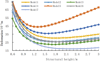
The Vierendeel truss was meshed into BEAM189 Elements. Then, a unit vertical load was applied to the finite element model. The height of the structure was adjusted from 0.6m to 3.0m with an interval of 0.3m, creating 7 models of different heights. Then, a total of 25 corresponding structural deformations were calculated for the 7 models (Figure 5).
Figure 5. The change curves of structural deformation with structural height
As shown in Figure 5, when the structural height was small, the truss deformation weakened significantly with the growing height; once the height surpassed a certain value, the deformation started to increase with the height. Overall, each of the 7 Vierendeel trusses had a reasonable height h01 that maximizes stiffness and minimizes deformation.
The reasonable heights h01 of 7 models are presented in Table 1. For Group 1, the reasonable height h01 decreased gradually, with the growing sectional sizes of upper and lower chords; For Group 2, reasonable height h01 increased significantly with the growing sectional size of vertical member; For Group 3, the reasonable height h01 decreased slowly with the growing length of the internode. These results agree well with the findings of analytical method.
According to the principle of equivalent stiffness, an equivalent solid web girder was designed for the Vierendeel truss in Table 1. For the equivalent solid web girder, the value of k=1.2; $m=\int \bar{M} M_{P} d s$ and $n=\int \overline{F_{Q}} F_{Q P} d s$ depend on the external load, but independent of the sectional size of the Vierendeel truss.
The 7 models have the same m and n values. $m=\int \bar{M} M_{P} d s=\frac{5 q l^{4}}{384}$ and $n=\int \overline{F_{Q}} F_{Q P} d s=\frac{q l^{2}}{8}$ could be derived through graph multiplication in structural mechanics. Substituting $m=\int \bar{M} M_{P} d s=\frac{5}{384} q l^{4} \quad, \quad n=\int \overline{F_{Q}} F_{Q P} d s=\frac{1}{8} q l^{2}$, q=1kN/m, and l=15m into formula (9), the reasonable height h02 of the Vierendeel truss could be calculated with analytical method. The calculated results are recorded in Table 1.
As shown in Table 1, the reasonable height value h02 calculated with analytical method is in line with the value of h01 obtained through finite-element analysis. The maximum error of 5% meets the requirement of engineering precision.
5.2 Influence of structural height on global stability
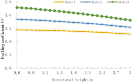
To verify the influence of structural height on global stability, a unit uniform surface load was applied to the upper chord of models 1, model 2 and model 3 in Table 1, respectively. Then, the buckling coefficient of each model was analyzed by ANSYS. The analysis results are shown in Figure 6.
Figure 6. The change curves of buckling coefficient with structural height
As shown in Figure 6, when the structural height was no greater than 3m, the buckling coefficients of the three Vierendeel truss models gradually decreased at slow speeds with the growing height. This is consistent with the results of the analytical method.
The object of engineering application is the roof of the recording studio hall (size: 21.6m × 24m) on the second floor of China Broadcast Audio & Video Publishing House. As shown in Figure 7, the structure of the hall is reinforced concrete Vierendeel truss (span: 20.8m; concrete strength grade: C40). According to formula (9), when the deformation is minimum, the structure height h0 is 1.9m. According to formula (14); when the buckling coefficient is minimum, the structure height h0 is smaller than 0.6m. Table 2 provides the deformations and buckling coefficients obtained with analytical method for the above structure, at the heights of 0.6m, 1.9m, and 3.47m, respectively.
Figure 7. The model of the Vierendeel truss
Table 2. The deformations and buckling coefficients of the structure
|
Height/m |
Deformation/(mm) |
Buckling coefficient |
|
0.6 |
83 |
19 |
|
1.9 |
34 |
23 |
|
3.47 |
41 |
27 |
As shown in Table 2, when the stiffness was maximized at the height of 1.9m, the deformation was 144% and 21% smaller than that at the heights of 0.6m and 3.47m, respectively, but the buckling coefficient was not much smaller than that at the contrastive heights. Thus, 1.9m is the reasonable height for the structure to obtain the maximum stiffness and global stability.
The stiffness and global stability of the Vierendeel truss were analyzed with analytical method and finite-element method. The following conclusions were drawn through the analysis:
(1) All the Vierendeel trusses have a reasonable height, which maximizes stiffness and minimizes deformation. The reasonable height increases significantly with the growing sectional size of vertical member, but decreases slowly with the growth in internode length, and the sectional sizes of upper and lower chords. This law provides an important basis for designers to rationalize the geometric parameters and height of the Vierendeel truss.
(2) When the structural height is small, the buckling coefficient decreases with the growing height; once the height surpasses a certain value, the buckling coefficient starts to increase with the height.
(3) Overall, structural height has a significant impact on stiffness, but a limited effect on global stability. To maximize the stiffness and global stability, the structural height should be rationalized mainly based on stiffness. Furthermore, the calculation formula for reasonable height based on stiffness, which was obtained with analytical method, meets the requirement of engineering precision, and could be used to optimize the stiffness and reduce the cost for designers in practical engineering.
This paper is supported by National Natural Science Foundation with project number 51208169 and Provincial Natural Science Foundation with project number E2019208322.
[1] Korol, R.M., El-Zanaty, M., Brady, F.J. (1977). Unequal width connections of square hollow sections in Vierendeel trusses. Canadian Journal of Civil Engineering, 4(2): 190-201. https://doi.org/10.1139/l77-024
[2] Shehata, A.A., Korol, R.M., Mirza, F.A. (1987). Joint flexibility effects on rectangular hollow section Vierendeel Trusses. Journal of Structural Mechanics, 15(1): 89-107. https://doi.org/10.1080/08905458708905110
[3] Basha, H.S., Goel, S.C. (1995). Special truss moment frames with Vierendeel middle panel. Engineering Structures, 17(5): 352-358. https://doi.org/10.1016/0141-0296(95)00018-3
[4] Dai, G.L., Tong, X.D., Huang, X.H., Liang, S.T. (2005). Application of laminated Vierendeel truss in high-position transfer story structure. Journal of Southeast University, 21(2): 184-189.
[5] Kim, J., Lee, J.H., Kim, Y.M. (2007) Inelastic behavior of staggered truss systems. Structural Design of Tall and Special Buildings, 16(1): 85-105. https://doi.org/10.1002/tal.361
[6] Hameed, A.W., Mahmod, K.S. (2008). Nonlinear analysis of reinforced fibrous concrete Vierendeel truss. Journal of Engineering, 14(2), 2364-2382.
[7] Machacek, J., Cudejko, M. (2009). Longitudinal shear in composite steel and concrete trusses. Engineering Structures, 31(6): 1313-1320. https://doi.org/10.1016/j.engstruct.2008.07.009
[8] Luo, J., Xiao, J.C., Lu, Z., Wei, X.X., Li, H.X., Li, S.L. (2014). Ultimate load-carrying capacity of pipe-plate Vierendeel truss joints. Advanced Materials Research, 838: 503-509. https://doi.org/10.4028/www.scientific.net/AMR.838-841.503
[9] Luo, J., Xiao, J.C., Lu, Z., Wei, X.X., Li, H.X., Li, S.L. (2013). Strength of welded pipe-plate joints. Researches and Applications in Mechanical Engineering, 2(4): 87-90.
[10] Zhang, S.W., Zhang, L.L., Zhang, Q. (2014). Innovation of old buildings repairing and vierendeel steel roof truss. Applied Mechanics and Materials, 501(1): 1043-1047. https://doi.org/10.4028/www.scientific.net/AMM.501-504.1043
[11] Silva, A.O., Júnior, N.O., Requena, J.A. (2015). Numerical modeling of a composite hollow Vierendeel-Truss. International Journal of Engineering and Technology, 7(3): 176-182. https://doi.org/10.7763/IJET.2015.V7.788
[12] Guo, Y.L., Chen, H., Pi, Y.L. (2017). In-plane failure mechanisms and strength design of circular steel planar tubular Vierendeel truss arches. Engineering Structures, 151: 488-502. https://doi.org/10.1016/j.engstruct.2017.08.055
[13] Ameer, J.S.A., Ghadhban, H.N., Hassan, M.A.H. (2017). Structural behavior of reinforced concrete Vierendeel truss to use in precast construction. Journal of Engineering and Sustainable Development, 21(6): 131-147.
[14] Kong, D., Zhang, W., Zhao, X. (2018). Experimental study on the seismic behavior of intersection joints of Vierendeel truss with column in weak-axis in steel grid cassette structures. Progress in Steel Building Structures, 20(4): 24-33.
[15] Nimnim, H.T., Shaaban, M.Q. (2018). Effect of concrete strength on the flexural behavior of Vierendeel steel and concrete composite beams. International Journal of Scientific and Technology Research, 7(5): 1-7.
[16] Jiang, L., Ma, K., Zhang, H., Li, L. (2018). The design method of steel Vierendeel beam with shear connector. Journal of Xi'an University of Architecture and Technology, 50(3): 354-360. https://doi.org/10.15986/j.1006-7930.2018.03.007
[17] Sarkis Fernandez, A.I., Granello, G., Liu, R., Capellaro, C., Palermo, A., Millar, P. (2018). He kōrero takiwā, he takiwā korero/stories within spaces, spaces defined by stories: A footbridge design concept for New Zealand. Structural Engineering International, 28(4): 418-424. https://doi.org/10.1080/10168664.2018.1484678
[18] Hassan, M.A., Nasir, H., Saeed, J. (2019). Experimental Investigation of high strength precast reinforced concrete walls used (Vierendeel truss form). IOP Conference Series: Materials Science and Engineering, 584(1): 012008. https://doi.org/10.1088/1757-899X/584/1/012008
[19] Al-Azawi, T.K., Abdulmajeed, M.W., Hashoosh, A.A. (2020). Control of footstep vertical vibration for Vierendeel truss- supported steel footbridges. IOP Conference Series: Materials Science and Engineering, 737(1): 012006. https://doi.org/10.1088/1757-899X/737/1/012006
[20] Pons Poblet, J.M. (2019). The Vierendeel truss: Past and present of an innovative typology. Arquitetura Revista, 15(1): 193-211. https://doi.org/10.4013/arq.2019.151.11