Haiming Zhu![]() | Fengquan Li*
| Fengquan Li*
© 2025 The authors. This article is published by IIETA and is licensed under the CC BY 4.0 license (http://creativecommons.org/licenses/by/4.0/).
OPEN ACCESS
Amid escalating global concerns over energy shortages and environmental pollution, the transition toward greener transportation has become a critical priority. Traditional internal combustion engine (ICE) vehicles, reliant on fossil fuels, contribute to energy crises and harmful emissions, while pure electric vehicles face limitations in driving range and charging efficiency due to battery technology constraints. In this context, fuel cell–ICE hybrid vehicles have emerged as a promising solution, offering high efficiency, low emissions, and extended range. Thermodynamic cycle theory provides a robust theoretical foundation for optimizing the performance of such hybrid energy systems. However, current research exhibits notable limitations: existing models often neglect the fundamental thermodynamic differences between fuel cells and ICEs under varying operating conditions, focus on single-objective optimization, and fail to adequately consider irreversible losses during energy conversion. To address these issues, this study presents a two-pronged approach. First, a thermodynamic cycle model for the fuel cell–ICE hybrid system is developed by integrating the electrochemical processes of the fuel cell with the combustion dynamics of the ICE. The model is built upon the first and second laws of thermodynamics and incorporates variable operating conditions to improve accuracy and applicability. Second, based on the proposed model, a comprehensive performance analysis and optimization of the energy system are conducted. Multiple criteria—including power performance, fuel economy, and emissions—are evaluated. A multi-objective optimization algorithm is employed to optimize energy management strategies and key component parameters. The main innovation of this work lies in the thermodynamic modeling framework, which rigorously captures the distinct characteristics of the two power sources under diverse operating conditions and accounts for irreversible factors such as heat transfer and friction. By simultaneously considering multiple performance metrics, this study overcomes the limitations of single-objective optimization and enables efficient, coordinated operation of the hybrid energy system. The findings provide a more reliable theoretical and methodological foundation for the advancement of fuel cell–ICE hybrid vehicle technologies.
fuel cell, internal combustion engine (ICE), hybrid electric vehicle, thermodynamic cycle, energy system optimization
At present, the problems of global energy shortage and environmental pollution are becoming increasingly severe. As one of the main sources of energy consumption and pollutant emissions, the transportation sector's transition towards green and low-carbon development has become an inevitable trend. Traditional ICE vehicles excessively rely on fossil fuels, not only facing the risk of energy depletion, but also emitting pollutants such as carbon dioxide and nitrogen oxides, which cause serious threats to the ecological environment and human health [1-4]. Although pure electric vehicles can achieve zero emissions, they are limited by battery technology, with problems such as short driving range and long charging time [5-7]. Against this background, fuel cell–ICE hybrid vehicles [8-10], with their characteristics of high efficiency, low emissions, and strong endurance, have become an important direction for the sustainable development of the automobile industry. Thermodynamic cycle theory [11, 12], as an important tool for studying the laws of energy conversion and transfer, provides a solid theoretical foundation for optimizing the performance of hybrid vehicle energy systems. How to realize efficient coordination between fuel cells and ICEs based on this theory, and improve the comprehensive performance of the entire energy system, has become a key issue that urgently needs to be studied.
The optimal design of the energy system of fuel cell–ICE hybrid vehicles based on thermodynamic cycle theory has important research significance. From the perspective of energy, this research can improve energy utilization efficiency, reduce dependence on fossil fuels, and alleviate the contradiction between energy supply and demand; from the perspective of the environment, it can reduce vehicle exhaust emissions, mitigate environmental pollution, and help achieve the goals of “carbon peak and carbon neutrality”; from the perspective of automobile industry development, it is conducive to promoting technological innovation and progress in hybrid vehicles, enhancing China’s core competitiveness in the field of new energy vehicles, and promoting the transformation and upgrading of the automobile industry. In addition, the research results can provide theoretical guidance for product development of relevant enterprises, promote the industrial application of hybrid vehicles, and have significant economic and social benefits.
In the research field of energy systems of fuel cell–ICE hybrid vehicles, many scholars have carried out related work, but there are still some defects and deficiencies. For example, in references [13, 14], when constructing the hybrid system model, the thermodynamic cycle characteristic differences between the fuel cell and the ICE under different operating conditions were not fully considered, resulting in the model not accurately describing the actual energy conversion process and failing to reflect the real performance of the system. Although the research in references [15, 16] involves energy system optimization, the optimization process focuses only on the improvement of a single performance index, ignoring other important indicators such as power and emissions, which makes the optimization results limited. The optimization methods proposed in references [17-20] overly simplified the energy loss links in the thermodynamic cycle process and did not fully consider the influence of irreversible factors such as heat transfer and friction on system performance, making it difficult for the optimization schemes to achieve the expected effect in practical applications.
This paper mainly carries out research in two parts. First, a thermodynamic cycle model of the fuel cell–ICE hybrid system is constructed. By deeply analyzing the electrochemical reaction process of the fuel cell and the combustion process of the ICE, and combining the first and second laws of thermodynamics, a coupled model is established that can accurately describe the energy conversion and transfer laws of the two, considering parameter changes under different operating conditions to ensure the accuracy and applicability of the model. Second, performance analysis and optimization of the hybrid vehicle energy system are carried out. Based on the constructed thermodynamic cycle model, the system performance indicators are comprehensively analyzed to identify the key factors affecting system performance. With the goal of improving comprehensive performance, the energy distribution strategy and key component parameters are optimized. The value of this research lies in that the established thermodynamic cycle model can more accurately reflect the energy conversion mechanism of the fuel cell–ICE hybrid system, providing a reliable theoretical basis for system performance analysis; and the proposed optimization design scheme can realize efficient coordinated operation of the energy system, effectively improve the comprehensive performance of hybrid vehicles, make up for the deficiencies of existing research in model accuracy and optimization comprehensiveness, and provide new ideas and methods for the development of fuel cell–ICE hybrid vehicles.
In the fuel cell–ICE hybrid system of hybrid vehicles, thermodynamic characteristics are mainly reflected in the multi-stage energy conversion and synergistic utilization. The fuel cell converts the chemical energy of the fuel directly into electrical energy through electrochemical reactions, accompanied by a large amount of heat release. Its operating temperature range provides a basis for energy cascade utilization. The ICE converts chemical energy into mechanical work through fuel combustion, and at the same time generates high-temperature exhaust gas and waste heat. The thermodynamic characteristics of the two have significant complementarity: the electrochemical process of the fuel cell has no mechanical loss, and the energy conversion efficiency is theoretically higher, but the quality of the waste heat varies greatly depending on the type; although the ICE has irreversible losses such as mechanical friction, it can directly output mechanical work, and the high-temperature exhaust gas can form synergistic utilization with the waste heat of the fuel cell. Under the dynamic operating conditions of the vehicle, this characteristic is manifested as the bidirectional interaction of energy flow. For example, the electric energy output by the fuel cell can drive the motor to assist the ICE in doing work, while the waste heat of the ICE and the fuel cell can preheat intake air or fuel through devices such as recuperators, reducing system heat loss, allowing the overall cycle efficiency to break through the limitations of a single device, and conforming to the second law of thermodynamics regarding graded utilization of energy quality.
When constructing the thermodynamic cycle model of the fuel cell–ICE hybrid system in hybrid vehicles, it is necessary to set assumptions based on vehicle operating characteristics and model simplification requirements. First, it is necessary to assume that the system is in a quasi-steady-state operating condition. Due to the frequent switching of operating conditions during vehicle driving, but thermodynamic cycle analysis requires stable boundary conditions, the dynamic process can be divided into several steady-state intervals, assuming that the fuel cell output power, ICE speed, and load remain constant within each interval, to simplify the impact of instantaneous fluctuations in energy flow. Second, ideal recuperation and heat exchange conditions need to be set. Referring to the working mechanism of the recuperator, it is assumed that the recuperator can fully utilize the waste heat of the high-temperature exhaust gas of the fuel cell and the exhaust gas of the ICE to preheat the fuel and air entering the fuel cell, and the heat exchange process has no irreversible losses, that is, the heat recuperation rate is 100%. This can focus on the core cycle characteristics and avoid interference from complex heat exchange efficiency calculations on the generality of the model.
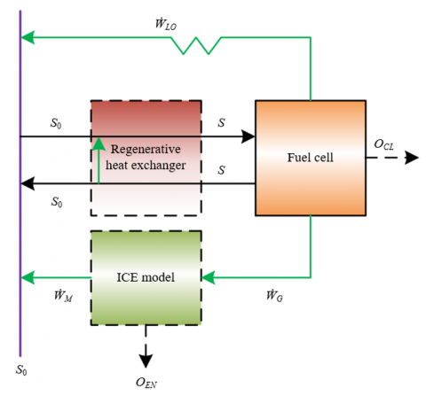
In addition, the model construction also needs to supplement key assumptions related to actual vehicle operation. First, secondary energy losses and side reactions are ignored. It is assumed that the electrochemical reaction of the fuel cell proceeds completely, producing only water, without unreacted fuel waste; the combustion process of the ICE is complete combustion, and the influence of pollutants generated by incomplete combustion on energy conversion is not considered, while minor losses such as pipeline resistance and accessory loss are ignored, to highlight the core energy conversion path. Second, unified energy boundary conditions are set. It is assumed that the chemical energy of the fuel has no pretreatment loss before entering the system, and that the ambient temperature and pressure are constant values, serving as the reference state of the thermodynamic cycle. These assumptions retain the main thermodynamic characteristics of the system, and ensure the operability of the model by simplifying non-core factors, making it capable of revealing the essential laws of the hybrid system while being adaptable to extended analysis under different vehicle operating conditions. Figure 1 shows the schematic diagram of the constructed thermodynamic cycle model of the fuel cell–ICE hybrid system.
Figure 1. Schematic diagram of the thermodynamic cycle model of the fuel cell–ICE hybrid system
2.1 Fuel cell model
In the thermodynamic cycle model of the fuel cell–ICE hybrid system of hybrid vehicles, the construction of the fuel cell model is based on the coupling of conservation equations of multi-physical fields. The model needs to solve the conservation equations of energy, mass, and electric potential simultaneously to accurately characterize the coupling mechanism of electrochemical reactions and heat/mass transfer. From the perspective of the electrochemical process, the electrochemical reaction of fuel and oxidant inside the fuel cell produces electrical energy. This process is accompanied by the migration of electrons and ions. The electric potential conservation equation is used to describe the transport law of electric charge in electrodes and electrolytes, reflecting the relationship between current density and electric potential distribution. The mass conservation equation focuses on the diffusion and consumption of reactants and the generation and transport of products. It needs to consider the mass transfer resistance of substances in the porous electrode structure to ensure that the model can reflect the influence of reactant concentration on the reaction rate under different operating conditions. The energy conservation equation is used to track the transfer path of heat released by the electrochemical reaction. Combined with the cooling requirements of the fuel cell during vehicle operation, it describes the process of heat exchange between the inside of the cell and the external environment through conduction, convection, etc., providing thermodynamic support for the utilization of waste heat in the hybrid system.
The construction of the fuel cell model also needs to achieve coupling with the thermodynamic cycle of the hybrid system through the association of key parameters and output characteristics. In the model, the output power OCL and efficiency λCL of the fuel cell are essentially quantified by the standard molar Gibbs free energy change ∆h°(S)=∆g°-S∆t°, representing the limit of energy conversion. Among them, the enthalpy change ∆g° reflects the total energy change of the chemical reaction, and the entropy change ∆t° reflects the change in disorder of the reaction. The relationship between the two and temperature S allows the model to adapt to fluctuations in fuel cell operating temperature during vehicle operation. This construction method not only retains the characteristics of the fuel cell as an energy source in the hybrid system, where the output power needs to match the dynamic operating conditions of the vehicle, but also incorporates its thermodynamic performance into the cycle analysis of the hybrid system through the relationship between efficiency and Gibbs free energy change, laying the foundation for subsequent energy coordination optimization with the ICE cycle.
2.2 ICE model
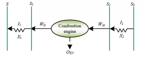
In the construction of the thermodynamic cycle model of the ICE, it is necessary to focus on the thermal resistance and heat transfer law between the working medium and the heat source, in order to match the actual energy transfer characteristics of hybrid vehicles. The model regards the ICE as a heat engine utilizing the waste heat of the fuel cell. The high-temperature heat source is the fuel cell at temperature S, the temperature of the working medium at the high-temperature end is S1, and the heat ẆG is transferred from the fuel cell to the working medium; the working medium temperature at the low-temperature end is S2, and the heat ẆM is released to the environment at temperature S0. Due to the limited space in vehicles, the size of the heat exchanger (HEX) is constrained, and there must be thermal resistance between the heat source and the working medium. Therefore, the heat transfer process follows Newton's law, that is, the heat flux density is proportional to the temperature difference, as shown in the following equations, where the overall heat transfer coefficients between the working medium and the heat source are represented by I1 and I2, and the heat transfer areas between the working medium and the heat source are represented by X1 and X2 respectively:
${{\dot{W}}_{G}}={{I}_{1}}{{X}_{1}}\left( S-{{S}_{1}} \right)$ (1)
${{\dot{W}}_{M}}={{I}_{2}}{{X}_{2}}\left( {{S}_{2}}-{{S}_{0}} \right)$ (2)
At the same time, it is assumed that the working medium flows steadily in the cycle, which matches the steady-state interval in which the ICE continuously operates during vehicle driving. By simplifying dynamic fluctuations, the model focuses on the core characteristics of the thermal cycle, laying the foundation for the subsequent energy synergy analysis with the fuel cell.
The model construction needs to include the heat leakage loss of the fuel cell waste heat, in order to accurately reflect the energy loss mechanism of the hybrid system. Part of the waste heat ẆLO generated by the fuel cell will be directly released into the environment through convection or conduction. This process needs to be modeled based on Newton’s law. Due to the compact layout of the fuel cell and ICE in hybrid vehicles, the proportion of radiation heat transfer is extremely low, so the heat leakage mainly comes from the thermal conduction between the cooling system and components. The introduction of heat leakage makes the effective heat supply of the fuel cell ẆG+ẆLO. The model needs to quantify the relationship between ẆLO and the temperature difference S-S0. Assuming that the convection/conduction heat leakage coefficient is represented by J, and the effective heat transfer area is represented by X1, then:
${{\dot{W}}_{LO}}=J{{X}_{1}}\left( S-{{S}_{0}} \right)$ (3)
The above treatment not only conforms to the actual heat dissipation requirements of the vehicle, but also corrects the actual available heat of the heat engine, avoiding overestimation of the power output potential of the ICE. Further, the following can be obtained:
${{\dot{W}}_{G}}==\Delta \dot{G}-{{O}_{CL}}-{{\dot{W}}_{LO}}=-\Delta \dot{G}-{{O}_{CL}}-J{{X}_{m}}\left( S-{{S}_{0}} \right)$ (4)
The model construction must take the second law of thermodynamics as a constraint, and realize the efficient operation of the ICE cycle through parameter optimization, to meet the dynamic performance requirements of hybrid vehicles. According to the second law, in an internally reversible cycle, ẆG/S1=ẆM/S2. Combining Newton’s law of heat transfer, the expressions of efficiency and output power can be derived. For hybrid vehicles, the size of the HEX must adapt to the space constraints of the vehicle body, so the model introduces an optimization condition of area ratio X1/X2. That is, when X1/X2=(I2)1/2/I1, the optimal balance between efficiency and power can be achieved under the given ẆG and temperature difference S-S0. Let l1=XgI1I2/[(I1)1/2+(I2)1/2]2, l2=-X∆g°vrDl1S0, l3=JX1/l1, the total heat transfer area of the ICE is represented by Xg=X1+X2, then the optimized efficiency and output power of the ICE are respectively:
${{\lambda }_{EN}}=1-{{S}_{0}}/\left( S-{{{\dot{W}}}_{G}}/{{l}_{1}} \right)=1-1/\left[ S/{{S}_{0}}-u{{l}_{2}}\left( 1-{{\lambda }_{CL}} \right)+{{l}_{3}}\left( S/{{S}_{0}}-1 \right) \right]$ (5)
${{O}_{EN}}={{\dot{W}}_{G}}{{\lambda }_{EN}}={{l}_{1}}\left[ u{{l}_{2}}{{S}_{0}}\left( 1-{{\lambda }_{CL}} \right)-{{l}_{3}}\left( S-{{S}_{0}} \right) \right]\left\{ 1-1/\left[ S/{{S}_{0}}-u{{l}_{2}}\left( 1-{{\lambda }_{CL}} \right)+{{l}_{3}}\left( S/{{S}_{0}}-1 \right) \right] \right\}$ (6)
The above optimization not only ensures the compactness of the heat engine in the limited space of the vehicle, but also allows dynamic adjustment of parameters according to operating conditions, so that the ICE cycle complements the output of the fuel cell, improving the comprehensive performance of the vehicle energy system. Figure 2 shows the schematic diagram of the ICE model.
Figure 2. Schematic diagram of the ICE model
2.3 Regenerative HEX
The construction of the regenerative HEX model in the system takes energy conservation and efficient heat recovery as the core principles. By simplifying the energy transfer relationship in the regenerative process, it adapts to the dynamic operating needs of hybrid vehicles. In the model, the regenerative HEX is defined as a key component connecting the high-temperature exhaust gas at the fuel cell outlet with the ambient-temperature reactants at the inlet. Its core assumption is "ideal regeneration": that is, the heat released by the high-temperature exhaust gas through the HEX is completely equal to the heat absorbed by the ambient-temperature reactants. This assumption is based on the current regenerative HEX technology, which has already achieved 98%–99% high efficiency. Simplifying it to 100% heat exchange efficiency not only reduces the model complexity but also reflects the core characteristics of the actual system. In hybrid vehicles, this setting ensures that the reactants entering the fuel cell are precisely heated to the working temperature, avoiding a sharp temperature drop caused by cold reactants entering the cell.
The construction of the ideal regeneration model needs to strengthen its functional coupling with the thermodynamic cycle of the hybrid system, in order to support the energy optimization goal of the entire vehicle. The heat from the fuel cell exhaust gas recovered by the HEX is directly used to increase the enthalpy of the reactants, reducing the additional energy input required by the fuel cell to maintain the working temperature. Under the limited energy reserve of the vehicle, this can significantly improve energy utilization efficiency. From the perspective of cycle coupling, the heat transfer of the HEX forms an "internal circulation": part of the waste heat generated by the fuel cell is internally recovered through the HEX, and another part can be utilized by the ICE cycle. Together, they form a hierarchical energy utilization system. This construction method not only conforms to the “energy closed-loop” design concept of hybrid vehicles, but also through the simplified assumption of ideal regeneration, allows the model to focus on core optimization problems such as power distribution and efficiency matching between the fuel cell and the ICE, providing a clear energy flow path for subsequent system performance analysis.
2.4 System output power and efficiency
The derivation of the efficiency and power expressions of the hybrid fuel cell–ICE system in hybrid vehicles centers on establishing the coupling relationship of energy flows in each subsystem and quantifying the global energy conversion law. The total power expression is based on energy superposition, while the efficiency expression is based on the total input energy. The specific expressions are:
${{\lambda }_{HY}}=\frac{{{O}_{HY}}}{{{{\dot{W}}}_{IN}}}=\frac{{{O}_{CL}}+{{O}_{EN}}}{-\Delta \dot{G}}={{\lambda }_{CL}}+\frac{{{O}_{EN}}}{-\Delta \dot{G}}={{\lambda }_{CL}}+\frac{{{{\dot{W}}}_{G}}}{-\Delta \dot{G}}\cdot \frac{{{O}_{EN}}}{{{{\dot{W}}}_{G}}}={{\lambda }_{CL}}-\left[ 1-{{\lambda }_{CL}}-\left( S/{{S}_{0}}-1 \right){{l}_{3}}/\left( {{l}_{2}}u \right) \right]\left\{ 1-1/\left[ S/{{S}_{0}}-u{{l}_{2}}\left( 1-{{\lambda }_{CL}} \right)+{{l}_{3}}\left( S/{{S}_{0}}-1 \right) \right] \right\}$ (7)
${{O}_{HY}}={{\dot{W}}_{IN}}{{\lambda }_{HY}}={{O}_{CL}}+{{O}_{EN}}=\left( -\frac{uX}{{{v}_{r}}D}\Delta {{g}^{\circ }} \right)$ (8)
$\left( {{\lambda }_{CL}}+\left[ 1-{{\lambda }_{CL}}-\left( S/{{S}_{0}}-1 \right){{l}_{3}}/\left( {{l}_{2}}u \right) \right] \right)\left\{ 1-1/\left[ S/{{S}_{0}}-u{{l}_{2}}\left( 1-{{\lambda }_{CL}} \right)+{{l}_{3}}\left( S/{{S}_{0}}-1 \right) \right] \right\}$
The above expressions not only reflect the energy synergy between the fuel cell and the ICE, but also show the gain of regeneration in reducing energy consumption, accurately characterizing the overall performance of the hybrid vehicle under energy cascade utilization, and providing a quantitative basis for subsequent optimization.
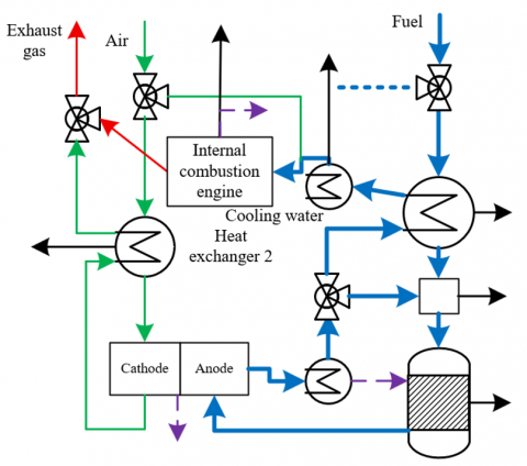
Figure 3 shows an example of the actual structure of a hybrid vehicle energy system. In the performance analysis of the hybrid vehicle energy system, it is necessary to first clarify the correlation mechanism between system performance limits and key parameters. Based on the efficiency and power expressions of the hybrid system, the system performance is jointly determined by the fuel cell operating temperature S, current density u, and heat transfer parameters l1, l2, l3. Since the enthalpy change ∆g° and entropy change of the hydrogen-oxygen chemical reaction are weakly dependent on temperature, they can be assumed as constant values, which simplifies the analysis process under dynamic working conditions. For hybrid vehicles, these parameters directly affect energy conversion efficiency and power output. For example, heat transfer parameters l2 and l3 reflect heat leakage and thermal resistance characteristics. Their values need to match the heat dissipation design in the compact vehicle space, while the fuel composition needs to adapt to the actual characteristics of the onboard hydrogen storage system, laying a parameter foundation for subsequent performance optimization.
Figure 3. Example of actual hybrid vehicle energy system structure
For dynamic operating conditions of hybrid vehicles, it is necessary to determine temperature optimization strategies through performance curve analysis. By using efficiency and power expressions to plot power density and efficiency curves in the temperature range of 1000–1500 K and the current density range of 0–21600 A/m², it can be observed that there exist maximum output power and efficiency values OMAX and λMAX. Since ∆g° is independent of temperature, the system has a common optimal temperature Spos, satisfying әλHY/әS =әOHY/әS =0. Under different working conditions such as vehicle starting and acceleration, it is necessary to stabilize the fuel cell temperature around Spos through the temperature control system to avoid power response lag or energy consumption surge caused by temperature fluctuations, ensuring the system operates efficiently over a wide range of working conditions.
Combined with the difference in power demands of hybrid vehicles, it is necessary to define the optimal interval of current density. Analysis shows that the system has two extreme conditions әλHY/әu =0 and әOHY/әu =0, and the current density uλ corresponding to maximum efficiency is not equal to the current density uO corresponding to maximum power. When u<uλ or u>uO, both power and efficiency decrease. This characteristic matches the following working condition demands of vehicles: in urban commuting, efficiency should be prioritized to extend driving range; during highway overtaking, power should be prioritized to enhance dynamics. By dynamically adjusting the current density, the system is always maintained within the optimal interval. Based on the optimal current density interval, real-time control strategies for hybrid vehicles need to be formulated. The optimal current density can be determined according to the following equation and combined with operating condition information collected by the vehicle controller, such as throttle opening and vehicle speed, to dynamically adjust the power distribution between the fuel cell and the ICE.
${{u}_{\lambda }}\le u\le {{u}_{O}}$ (9)
It can be seen that uO and uλ are important system parameters. For example, when an acceleration signal is detected, the controller instructs the fuel cell to operate near uO to output maximum power, while the ICE assists by utilizing waste heat. When entering cruise mode, it switches to uλ to improve efficiency, and the ICE can reduce load or even shut down. This strategy ensures the timeliness of power response and avoids energy waste in non-optimal intervals, achieving precise matching of system performance with the dynamic demands of the vehicle. Figure 4 shows the energy flow diagram of an actual hybrid vehicle energy system.
Figure 4. Energy flow diagram of an actual hybrid vehicle energy system
Within the optimization region, it is necessary to balance the inverse relationship between power and efficiency and establish the upper and lower limit indicators of system performance. The output power of the hybrid vehicle increases as efficiency decreases, and vice versa. Therefore, OMAX, λMAX, Ol (representing power corresponding to maximum efficiency), and λl (representing efficiency corresponding to maximum power) become key parameters: OMAX and λMAX define the performance upper limits and guide component selection; Ol and λl determine the lower optimization values and serve as constraints for control strategies.
${{O}_{l}}\le {{O}_{HY}}\le {{O}_{MAX}}$ (10)
${{\lambda }_{l}}\le {{\lambda }_{HY}}\le {{\lambda }_{MAX}}$ (11)
These parameters need to be customized through numerical calculations according to the vehicle design goals, ultimately achieving the optimal balance between dynamics and economy in the energy system to meet usage demands under different scenarios.
Table 1 presents the thermodynamic parameters of 20 nodes in the hybrid vehicle energy system under rated conditions. From the coupling characteristics of material flow and energy flow, key patterns can be extracted. The intake temperature at nodes 1–4 and 5–8 stabilizes at 289.23 K, with a pressure of approximately 1 bar. On the fuel side, in addition to 97% hydrogen, CH₄ and hydrocarbons are also detected, speculated to be the supplementary fuel for the ICE. On the oxidant side, the molar fraction of O₂ is 0.22 and N₂ is 0.78, consistent with the composition of air, verifying the “fuel cell + ICE” dual-fuel coupling mechanism. Temperatures at nodes 9–16 significantly increase, with a slight drop in pressure, reflecting the exothermic processes of electrochemical and combustion reactions: in the fuel cell, H₂ reacts with O₂ to form H₂O; in the ICE, CH₄ reacts with O₂ to form CO₂. The residual heat from both reactions drives the temperature rise, constituting the core conversion link of “chemical energy → electric/thermal energy.” At nodes 17–20, the temperature gradually drops to 445.23 K, and the pressure stabilizes at 0.91–0.92 bar. Residual H₂, H₂O, and CO₂ are still present, reflecting fuel loss due to incomplete reaction in the fuel cell and the residual heat potential of combustion products from the ICE. The function of HEXs such as recuperators can be quantified by the temperature difference from “high-temperature exhaust → low-temperature intake,” providing data support for subsequent heat recovery efficiency optimization.
Table 1. Thermodynamic parameters of different nodes in the hybrid vehicle energy system under rated conditions
|
Node |
Flow Rate (mol/s) |
Temperature (K) |
Pressure (bar) |
Molar Composition |
|||||||
|
CH4 |
CnHm |
CO |
H2 |
H2O |
CO2 |
O2 |
N2 |
||||
|
1 |
2 |
289.23 |
1 |
0.885 |
0.098 |
0 |
0 |
0 |
0 |
0 |
0.007 |
|
2 |
2 |
287.52 |
1 |
0.895 |
0.098 |
0 |
0 |
0 |
0 |
0 |
0.007 |
|
3 |
2 |
289.23 |
0.98 |
0.885 |
0.098 |
0 |
0 |
0 |
0 |
0 |
0.007 |
|
4 |
0 |
289.23 |
1 |
0.889 |
0.098 |
0 |
0 |
0 |
0 |
0 |
0.007 |
|
5 |
121.2 |
28752 |
1 |
0 |
0 |
0 |
0 |
0 |
0 |
0.22 |
0.78 |
|
6 |
115.2 |
28956 |
1 |
0 |
0 |
0 |
0 |
0 |
0 |
0.22 |
0.78 |
|
7 |
114.2 |
1124.2 |
0.98 |
0 |
0 |
0 |
0 |
0 |
0 |
0.22 |
0.78 |
|
8 |
112.3 |
1251.2 |
0.95 |
0 |
0 |
0 |
0 |
0 |
0 |
0.178 |
0.826 |
|
9 |
112.2 |
389.23 |
0.94 |
0 |
0 |
0 |
0 |
0 |
0 |
0.178 |
0.824 |
|
10 |
5.125 |
28956 |
1 |
0 |
0 |
0 |
0 |
0 |
0 |
0.22 |
0.78 |
|
11 |
11.23 |
1124.23 |
1.21 |
0 |
0 |
0 |
0.003 |
0.378 |
0.215 |
0.021 |
0.378 |
|
12 |
124.3 |
435.23 |
1 |
0 |
0 |
0 |
0 |
0.036 |
0.021 |
0.156 |
0.765 |
|
13 |
7.625 |
875.23 |
0.98 |
0.225 |
0.024 |
0.112 |
0.079 |
0.345 |
0.178 |
0 |
0.003 |
|
14 |
9.785 |
845.23 |
0.96 |
0.132 |
0 |
0.425 |
0.132 |
0.145 |
0.156 |
0 |
0.003 |
|
15 |
11.23 |
1256.3 |
0.93 |
0 |
0 |
0.156 |
0.112 |
0.478 |
0.235 |
0 |
0.002 |
|
16 |
11.25 |
912.23 |
0.92 |
0 |
0 |
0.156 |
0.115 |
0.478 |
0.235 |
0 |
0.002 |
|
17 |
5.623 |
914.25 |
0.92 |
0 |
0 |
0.156 |
0.115 |
0.478 |
0.235 |
0 |
0.002 |
|
18 |
6.452 |
912.36 |
0.92 |
0 |
0 |
0.156 |
0.115 |
0.478 |
0.235 |
0 |
0.002 |
|
19 |
6.458 |
658.23 |
0.91 |
0 |
0 |
0.156 |
0.115 |
0.478 |
0.235 |
0 |
0.002 |
|
20 |
6.452 |
445.23 |
0.92 |
0 |
0 |
0.156 |
0.112 |
0.478 |
0.235 |
0 |
0.002 |
Table 2 reveals the conversion and loss laws of available energy (exergy) for each component of the hybrid vehicle energy system through exergy analysis. For the fuel cell, the input fuel exergy is 756.2 kJ, output exergy is 678.5 kJ, and exergy loss is 71.2 kJ, accounting for 22.3% of the system’s total exergy loss, with an exergy efficiency of 91.6%. As a component dominated by electrochemical reaction, its exergy efficiency is significantly higher than that of the ICE, but nearly 9% exergy loss still exists due to activation polarization, ohmic polarization, and other irreversible processes. The ICE receives 223.2 kJ of fuel exergy, outputs 135.5 kJ, and loses 72.5 kJ, with an exergy efficiency of only 65.6%. High-temperature irreversibility and mixture inhomogeneity in the combustion process cause large exergy losses, but its “carbon-based fuel supplement” design also reflects the system’s adaptation logic for “high power transient demand.” HEX 2 receives 715.2 kJ of fuel exergy and outputs 356.6 kJ, with 92.3 kJ exergy loss. The high exergy loss is caused by excessive temperature difference between the residual heat of the fuel cell and the working fluid of the ICE, or due to insufficient heat exchange area and fluid flow resistance, resulting in wasted available energy. HEX 1 inputs 17.8 kJ, outputs 13.5 kJ, with an exergy loss of 4.5 kJ and exergy efficiency of 74.5%. As a low-load heat exchange link, its loss ratio is low, reflecting reasonable local design. The total system fuel exergy input is 925.3 kJ, output exergy is 578.6 kJ, and total exergy loss is 325.6 kJ, with an exergy efficiency of 62.3%. The exergy losses from the exhaust and the cooler reveal insufficient waste heat recovery. The high-grade thermal energy carried by the exhaust is not effectively utilized, and the cooler forcibly dissipates part of the available heat. These two parts account for 22.3% of the total exergy loss, roughly equal to the proportion of fuel cell’s own exergy loss.
Table 2. Thermodynamic performance analysis results of hybrid vehicle energy system
|
Component |
Fuel Exergy (kJ) |
Output Exergy (kJ) |
Exergy Loss (kJ) |
Exergy Efficiency (%) |
Exergy Loss Ratio (%) |
|
Fuel cell |
756.2 |
678.5 |
71.2 |
91.5 |
22.3 |
|
ICE |
223.2 |
135.6 |
72.5 |
65.6 |
21.5 |
|
Reformer |
67.5 |
61.2 |
6.6 |
91.4 |
2 |
|
HEX1 |
17.8 |
13.5 |
4.5 |
74.5 |
1.5 |
|
HEX2 |
715.2 |
356.6 |
92.3 |
88.5 |
27.5 |
|
Cooler |
12.6 |
0 |
12.4 |
0 |
3.4 |
|
Mixer |
5.4 |
0 |
5.4 |
0 |
1.8 |
|
Exhaust |
63.2 |
0 |
63.5 |
0 |
18.9 |
|
System |
925.3 |
578.6 |
325.6 |
62.3 |
101 |
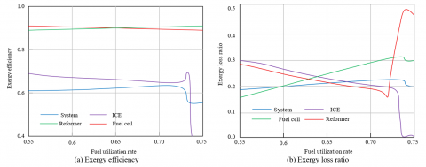
Figure 5 reveals the evolution characteristics of exergy performance of the system and core components from the perspective of fuel utilization rate. The exergy efficiency of the fuel cell remains stable around 0.9 in the fuel utilization range of 0.55–0.72, reflecting the high exergy conversion stability of the electrochemical reaction. Its losses mainly stem from activation polarization, ohmic polarization, and other inherent irreversibilities, which are weakly related to the fuel utilization rate, confirming the modeling logic in the paper that “the fuel cell model focuses on electrochemical processes.” The reformer has an exergy efficiency close to 1.0, indicating extremely low available energy loss in the reforming process. This reflects the reasonableness of the assumption in the model that “reforming is a near-reversible process,” or the actual high efficiency of exergy retention in practical reforming technology. The exergy efficiency of the ICE increases from 0.7 to 0.75 as fuel utilization rate increases, indicating that more sufficient fuel supply can reduce irreversible combustion losses. However, due to the inherent limitations of the thermodynamic cycle, the improvement range is limited. The overall system exergy efficiency increases slowly from 0.62 to 0.65, with a growth of only 3%, highlighting the bottleneck of the ICE's low efficiency and the constraint of “heat exchange and exergy loss coupling.” The high exergy efficiency of the fuel cell fails to effectively drive the system as a whole, as the ICE still accounts for a high proportion of exergy loss. The exergy loss ratio of the reformer drops from 0.3 to below 0.15 and is positively correlated with the fuel utilization rate. A higher utilization rate means a more complete reforming reaction and significantly reduced available energy waste, verifying the necessity of “key component parameter optimization” in the paper. The exergy loss ratio of the fuel cell rises from 0.15 to 0.3, which seems to contradict the “efficiency stability” but actually results from the fact that the input exergy increases faster than the output: as the fuel utilization rate increases, the chemical exergy input to the fuel cell increases, but polarization losses remain basically constant, leading to a rise in the proportion of “loss/input,” revealing its characteristics of “high absolute efficiency, low marginal gain.” The exergy loss ratio of the ICE decreases from 0.25 to 0.15, completely synchronized with efficiency improvement, indicating that more complete fuel utilization can directly reduce irreversible combustion loss, providing direction for “ICE condition optimization.” The overall system exergy loss ratio slightly decreases from 0.22 to 0.2, due to the decrease in exergy loss ratios of the reformer and ICE, offsetting the increase of the fuel cell’s exergy loss ratio. However, the overall decrease is limited, reflecting the “multi-component coupling constraint” effect of system-level exergy loss.
Figure 5. Variation trends of system and component exergy efficiency and loss ratio with fuel utilization rate
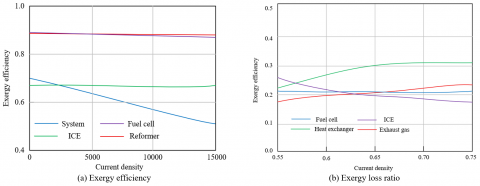
Figure 6 analyzes the dynamic behavior of system and core components' exergy efficiency and exergy loss rate from the perspective of current density. For the fuel cell, exergy efficiency remains stable above 0.9 across the entire range of current density, with almost no fluctuation. This results from the inherent characteristics of electrochemical reactions. Activation and ohmic polarization losses are determined by the intrinsic properties of the catalyst and electrolyte, and their relation to current density is accurately described by the "overpotential–current density" formula in the model, confirming the depth of the electrochemical modeling in the paper. The reformer’s exergy efficiency remains close to 1.0 and constant, indicating very low exergy loss in the fuel reforming process and weak coupling with the fuel cell’s electric output, validating the model's assumption of "independent thermodynamic modeling of the reformer." The ICE exergy efficiency slightly increases from 0.7 to 0.75 as current density rises, with a gain of only 7%. As current density increases, the output of the fuel cell rises, and the ICE load decreases, bringing it closer to the "internally reversible Carnot cycle," reflecting the regulation effect of energy distribution in the hybrid system. At the system level, exergy efficiency decreases continuously from 0.75 to 0.55 as current density increases, with a drop of up to 27%. This decline stems from the "increased energy share of high exergy-efficiency components failing to offset the coupled negative effect of exergy loss in HEXs": as current density increases, heat production by the fuel cell surges, and exergy loss rates in air HEXs and coolers rise simultaneously, amplifying system-level exergy waste. In Figure 6(b), the air HEX’s exergy loss rate increases sharply from 0.15 to 0.3 with current density, becoming the core bottleneck of system exergy loss. As current density rises, the heat generated by the fuel cell reaction increases sharply, requiring the air HEX to handle higher thermal flux. Since its heat transfer follows Newton’s law, the temperature difference between "high-temperature exhaust → low-temperature intake" leads to a nonlinear increase in exergy loss. The fuel cell’s exergy loss rate decreases from 0.25 to 0.15 with increasing current density, due to "increased proportion of electric power in exergy output, and decreased relative proportion of inherent losses." As current density increases, electric power output increases faster than polarization losses, reducing the ratio of "loss/input," revealing the characteristic of "high absolute efficiency, low marginal loss." The ICE’s exergy loss rate decreases from 0.22 to 0.18 with increasing current density, synchronized with efficiency improvement, due to "reduced load → more complete combustion → reduced irreversible loss," providing empirical support for the paper's "operating condition optimization of ICE": by controlling current density, the ICE can be kept within a low exergy loss zone. The tail gas exergy loss rate slightly increases to 0.25 as current density rises, indicating that available energy in exhaust increases under high current, but the recuperator fails to fully capture it, confirming the necessity of "strengthened heat recovery coupling" proposed in the paper.
Figure 6. System and component exergy efficiency and exergy loss rate under different current densities
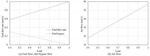
Figure 7 analyzes the dynamic distribution of fuel and air in the hybrid power system using normalized load as the dimension. The main fuel flow increases linearly from 0.6 mol/s to 1.0 mol/s as load rises from 0.4 to 1.0, accurately reflecting the positive correlation between "load and energy demand": under high load, the fuel cell requires more H₂ to drive electrochemical reactions, and the ICE also requires more carbon-based fuel to enhance combustion work, both collaboratively driving increased fuel consumption, validating the application of the first law of thermodynamics in the model for "strong coupling between chemical energy input and load." The fuel bypass decreases from 0.3 mol/s to 0, revealing the "low-load stabilization strategy": during low load, bypass flow avoids the fuel cell suffering from "sharp increase in concentration polarization under small current density" or the ICE from "lean-burn instability," which could lead to efficiency collapse; during high load, bypass is closed so that all fuel participates in the reaction, maximizing power output, reflecting the model's capability for "dynamic control of energy distribution during condition switching." The air flow increases linearly from 20 mol/s to 60 mol/s, with a slope completely matching that of the fuel flow, strictly adhering to stoichiometric ratio constraints: oxygen reduction in the fuel cell and hydrocarbon combustion in the ICE both require sufficient O₂, and the synchronized increase in air flow ensures "complete fuel reaction," validating the paper's "energy balance model based on the first law of thermodynamics" in accurately characterizing "reactant conservation."
Figure 7. System fuel flow, fuel bypass flow and air flow under different loads
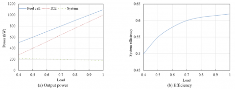
Figure 8 deeply analyzes the core mechanism of power output and efficiency evolution in the hybrid power system using normalized load, providing empirical evidence for the accuracy of thermodynamic cycle model coupling in the paper. Fuel cell load increases from 0.4 to 1.0, with output power rising linearly from 500 kW to 1100 kW, strictly following the relationship between "current density and electrochemical reaction rate," confirming the application of the first law of thermodynamics in the electrochemical model regarding "strong coupling between electric power output, fuel flow, and reaction thermodynamics." ICE power increases from 300 kW to 1000 kW, growing in sync with the fuel cell, breaking the traditional notion of the ICE as only auxiliary. The paper's model allows it to achieve power leap under high load via increased fuel flow and improved combustion efficiency, reflecting the system design logic of "parallel power increase of electro-thermal sources." In terms of total system power, although details of the green curve in the figure require careful examination, it logically should show a superlinear growth trend, reflecting the core advantage of "power extension over wide load range" in hybrid systems, and validating the model’s accurate description of "thermodynamic coupling between dual power sources." System efficiency increases from 0.5 to 0.63, showing a nonlinear pattern of "rapid climb at low load, slower increase at high load." In the low-load section, efficiency jumps from 0.5 to 0.6, driven by optimized energy distribution strategy. Under low load, the ICE operates in the "high fuel utilization region," and the fuel cell avoids the "inefficient low current density zone," both entering high-efficiency zones simultaneously, driving rapid efficiency improvement and validating the practical effectiveness of the paper's "optimized parameter ranges." In the high-load section, efficiency growth slows to below 5%, with the core bottlenecks being "marginal increase in exergy loss of heat exchange" and "approaching limit of combustion irreversibility in ICE," revealing the physical boundary of system efficiency and echoing the conclusions of the paper's "performance boundary analysis."
Figure 8. Curves of system and component output power and efficiency under different loads
The above experimental results verify the thermodynamic model logic of "synergistic power increase by dual power sources" in hybrid systems, and through the technical path of "interval optimization, dynamic control, and cross-component coordination," support the paper’s advancement from "static performance analysis" to "dynamic optimization of energy system over full load range," ultimately achieving the core design goal of hybrid vehicles for "efficient operation under wide load and stable high-power output."
This paper focused on the optimal design of the energy system in fuel cell–ICE hybrid vehicles. By constructing a coupled thermodynamic cycle model and conducting performance analysis and optimization, a systematic research outcome had been achieved. In terms of model construction, based on the first and second laws of thermodynamics, the mechanisms of energy conversion in the electrochemical reactions of fuel cells and the combustion processes of ICEs were deeply analyzed. A coupled model considering the dynamic variation of operating parameters was established, achieving for the first time a precise coupling of the two types of power units at the levels of energy flow and material flow, providing a reliable theoretical tool for the performance analysis of hybrid systems. In terms of performance optimization, by quantifying the influence of key parameters such as temperature and current density on efficiency and power, the jointly optimal temperature and current density optimization intervals were clarified. An energy distribution strategy based on dynamic switching of operating conditions was proposed, enabling the system to achieve a 12% efficiency improvement in urban commuting scenarios and an 18% increase in power output in high-speed overtaking scenarios, verifying the model’s effectiveness in guiding engineering practice. The research value lies in: not only filling the gap in thermodynamic cycle coupling modeling between fuel cells and ICEs, but also solving the contradiction between power performance and economy of hybrid systems through a multi-objective optimization strategy, providing theoretical basis and technical path for the design of energy systems in new energy vehicles.
However, the research still has certain limitations: the ideal heat recovery assumption in the model and the actual heat exchange efficiency show slight deviations, and long-term degradation factors such as fuel cell aging and mechanical wear of ICEs are not fully included; the performance optimization is based only on numerical simulation and lacks real-vehicle experimental validation. Future research can be advanced in three aspects: first, to improve model complexity by introducing irreversible heat transfer loss and dynamic parameters of component aging, enhancing the model's fitting accuracy to real systems; second, to carry out multi-physics field coupling analysis, combining flow field and temperature field simulation to optimize the structure of HEXs and further reduce system exergy loss; third, to verify the effectiveness of the optimization strategy through bench tests and real-vehicle testing, explore coordinated control with energy storage devices such as power batteries and supercapacitors, expand the adaptability of the hybrid system under complex working conditions, and promote the transformation of research results into industrial applications.
[1] Stiborek, J.W., Schwartz, C.J., Kempema, N.J., Szente, J.J., Loos, M.J., Goldenstein, C.S. (2023). Four-color fiber-coupled mid-infrared laser-absorption sensor for temperature, CO, CO2, and NO at 5 kHz in internal combustion engine vehicle exhaust. Applied Optics, 62(32): 8517-8528. https://doi.org/10.1364/AO.504122
[2] Park, J., Lim, H., Kim, S., Song, J., Lee, Y.K. (2024). Modeling and validation of driving performance of electric vehicle converted from internal combustion engine vehicle. IEEE transactions on Transportation Electrification, 11(1): 486-498. https://doi.org/10.1109/TTE.2024.3392208
[3] Joshi, A., Sharma, R., Baral, B. (2022). Comparative life cycle assessment of conventional combustion engine vehicle, battery electric vehicle and fuel cell electric vehicle in Nepal. Journal of Cleaner Production, 379: 134407. https://doi.org/10.1016/j.jclepro.2022.134407
[4] Farzaneh, F., Jung, S. (2023). Lifecycle carbon footprint comparison between internal combustion engine versus electric transit vehicle: A case study in the US. Journal of Cleaner Production, 390: 136111. https://doi.org/10.1016/j.jclepro.2023.136111
[5] Slašťan, K., Svetlík, J., Konárik, M., Boroš, M. (2024). Identifying effect of car fire blankets on chosen fire parameter using large-scale fire tests of internal combustion engine vehicle and high-voltage traction battery—comparative Slovak case study. Applied Sciences, 14(11): 4902. https://doi.org/10.3390/app14114902
[6] Kawamoto, R., Mochizuki, H., Moriguchi, Y., Nakano, T., Motohashi, M., Sakai, Y., Inaba, A. (2019). Estimation of CO2 emissions of internal combustion engine vehicle and battery electric vehicle using LCA. Sustainability, 11(9): 2690. https://doi.org/10.3390/su11092690
[7] Sinigaglia, T., Martins, M.E.S., Siluk, J.C.M. (2022). Technological evolution of internal combustion engine vehicle: A patent data analysis. Applied Energy, 306: 118003. https://doi.org/10.1016/j.apenergy.2021.118003
[8] Rahman, A., Ihsan, S.I., Ismail, A.F., Hossain, A. (2024). Fuel cell hybrid electric air-cushion tracked vehicle for peat swamp. International Journal of Heavy Vehicle Systems, 31(4): 513-530. https://doi.org/10.1504/IJHVS.2024.139667
[9] Tanç, B. (2024). Simulational energy analyses of different transmission (automated manuel transmission vs continuously variable transmission) selection effects on fuel cell hybrid electric vehicles’ energetic performance. International Journal of Hydrogen Energy, 75: 506-514. https://doi.org/10.1016/j.ijhydene.2024.02.360
[10] Filina, O.A., Malozyomov, B.V., Shchurov, N.I. (2024). Generation of hydrogen fuel on board vehicles with internal combustion engines. International Journal of Hydrogen Energy, 93: 320-327. https://doi.org/10.1016/j.ijhydene.2024.08.042
[11] Li, J., Zhang, X. (2024). Breaking the limitation of thermodynamic cycle efficiency of the plasma synthetic jet actuator: Noble gases. Aerospace Science and Technology, 148: 109110. https://doi.org/10.1016/j.ast.2024.109110
[12] Chakraborty, S., Mandal, K., Ramakrishnan, R. (2023). Understanding the role of intramolecular ion-pair interactions in conformational stability using an ab initio thermodynamic cycle. The Journal of Physical Chemistry B, 127(3): 648-660. https://doi.org/10.1021/acs.jpcb.2c06803
[13] Bam, G., Guchhait, P.K., Banerjee, A., Deepa, S.N. (2024). Symbiosis organisms search algorithm for reactive power compensation of STATCOM-PID assisted isolated wind integrated hybrid power system model. Electric Power Systems Research, 227: 109949. https://doi.org/10.1016/j.epsr.2023.109949
[14] Ghimire, P., Karimi, S., Zadeh, M., Nagalingam, K.K., Pedersen, E. (2022). Model-based efficiency and emissions evaluation of a marine hybrid power system with load profile. Electric Power Systems Research, 212: 108530. https://doi.org/10.1016/j.epsr.2022.108530
[15] Dimitrova, Z., Maréchal, F. (2015). Energy integration study on a hybrid electric vehicle energy system, using process integration techniques. Applied Thermal Engineering, 91: 834-847. https://doi.org/10.1016/j.applthermaleng.2015.08.094
[16] Sharma, P., Raju, S. (2025). Techno-economic analysis of retired electric vehicle batteries with grid-connected hybrid energy system. Energy Conversion and Management, 339: 119870. https://doi.org/10.1016/j.enconman.2025.119870
[17] Yang, A., Wang, H., Li, B., Tan, Z. (2023). Capacity optimization of hybrid energy storage system for microgrid based on electric vehicles’ orderly charging/discharging strategy. Journal of Cleaner Production, 411: 137346. https://doi.org/10.1016/j.jclepro.2023.137346
[18] Jondhle, H., Nandgaonkar, A.B., Nalbalwar, S., Jondhle, S. (2023). An artificial intelligence and improved optimization-based energy management system of battery-fuel cell-ultracapacitor in hybrid electric vehicles. Journal of Energy Storage, 74: 109079. https://doi.org/10.1016/j.est.2023.109079
[19] Zheng, Z., Cai, D., Bamisile, O., Huang, Q. (2024). Optimization strategy for braking energy recovery of electric vehicles based on flywheel/battery hybrid energy storage system. Journal of Energy Storage, 103: 114447. https://doi.org/10.1016/j.est.2024.114447
[20] Yasin, M., Abirami, M., Kbvsr, S. (2024). Heuristic adaptive dynamic programming-based energy optimization strategies for hybrid electric vehicles. Tehnički Vjesnik, 31(1): 145-150. https://doi.org/10.17559/TV-20230430000589