Andrea Greppi | Luca Battaglia | Alberto Clarich | Rosario Russo | Zhongli Wen | Enrico Nobile*
OPEN ACCESS
The GASVESSEL project aims to prove the techno-economic feasibility of a new CNG (Compressed Natural Gas) transport concept, enabled by a novel patented Pressure Vessel manufacturing technology and a new conceptual ship design including safe on- and off-loading solution.
This article describes the CFD models that have been defined for a preliminary safety assessment on the ship. Analytical models and numerical simulations were used in order to have a better understanding of the problem and give to the partners of the project the indications necessary to identify the proper solutions to improve safety on the ship.
First, a possible gas leakage in the hold is analyzed, considering all side effects caused by the low temperature exposure, and a CFD study on the flow through a small crack with a high pressure differential is studied. Then the focus is moved to the compressor room, where different ventilation solutions are analyzed to reduce explosion risks in case of gas dispersion and to allow partners to understand which one best suits the requirements. Finally, an emergency vent mast system, that is activated in case of critical gas dispersion to evacuate the gas from the hold, is analyzed. In particular, the aim is to determine if the gas cloud will impact the exhaust chimneys at the ship's stern or the accommodations at the ship's bow.
CNG, natural gas, CFD, safety, ship
The study reported here is considered as a part of a preliminary safety assessment on the ship involved in the GASVESSEL project since all simulations are done considering gas leakages or gas impact on neighboring zones such as the rest of the harbor. It should be emphasized that it is a preliminary analysis, because the ship is not yet fully defined and, therefore, some hypotheses had to be made.
1.1 The GASVESSEL project
The GASVESSEL project [1-3] provides a novel, efficient and flexible method for transporting Compressed Natural Gas (CNG), and it involves a consortium formed by thirteen partners among naval manufacturing companies and research centres with eight countries represented: Belgium, Cyprus, Germany, Greece, Italy, Norway, Slovenia and Ukraine. The European contribution is invested to diversify Europeans supply routes of energy and to open up new possibilities to exploit stranded, associated and flared gas where this is currently economically not viable. The research results are expected to contribute to the energy security of the European Union and they will be particularly useful for small consumers such as Mediterranean and Aegean Sea Islands, where other means of natural gas supply are economically unfeasible.
Nowadays technology used to build cylinders for the transportation makes CNG ships not viable. The main innovation proposed is a novel patented solution for the manufacturing of up to 70% lighter pressure vessels compared to steel alternatives, enabling new CNG ship designs with much higher payloads and, as a consequence, dramatically lower transportation cost per unit of gas. These containers can store natural gas at pressures of up to 30 MPa and are made of steel reinforced with fibreglass and carbon fibres to ensure the required stability.
1.2 Studies considered
In this article we present the methods used to perform part of a preliminary safety assessment on the ship involved in the project and results obtained. The attention is focused on three critical zones of the ship according with the report [4] in which they are named respectively as Recommendations number 8, 20 and 23 and state as following:
Rec. 8: Perform study to analyze low temperature exposure to hold area and pressure profile within cargo hold during cylinder leakage scenario and provide adequate safeguards accordingly.
Rec. 20: Review need to perform a fire explosion analysis to understand the effect on the adjacent area in case of a gas leak in compressor room and provide adequate safeguards as applicable.
Rec. 23: Perform gas dispersion analysis to optimized vent mast location and height to ensure gas release from vent mast will not lead to migration of gas to hazardous zone or accommodation area, which can result in a fire hazard.
CFD simulations and analytical models are the tools used to perform studies needed to create the safety assessment needed. In particular, the attention was focused upon the mass and heat transfer to reach equilibrium conditions and occurring during a gas leakage. In fact, first the equilibrium conditions of the hold after the loading procedures were calculated [5, 6]. After that the focus is moved to a possible leakage from the cylinders. One important aspect to consider is the high pressure inside them, 30 MPa, that, during an expansion due to a leakage, decreases to 0.1 MPa of the hold atmosphere, creating a significant decrease in temperature due to the isenthalpic expansion of the methane.
To avoid fire issues the hold has an inert atmosphere, while in the compressor room two solutions were taken in account: an inert atmosphere to simulate the hold and a ventilation system to keep the air clean even with a methane leakage. The last study regarded a gas cloud spread after releasing pressure in a cargo tank, formed by four cylinders, from the vent mast, the emergency exhaust system. These two last studies are considered preliminary since the detailed planimetry of the compressor room and the piping system scheme were not defined at the time of the present study.
Not only CFD simulations, but also analytical models, when possible [7-9], have been implemented to have a wider understanding of the phenomena of interest occurring on the ship. To better highlight the peculiarities of the three different studies, they are presented separately in the following pages.
2.1 Ship-hold studies
First Recommendation analyzed:
Rec. 8: Perform a study to analyze low temperature exposure to hold area and pressure profile within cargo hold during cylinder leakage scenario and provide adequate safeguards accordingly.
The first theme analyzed was a gas leakage in the inert ship-hold. In this case the major concern was the critical overpressure for structures, and the main goal was to determine the time needed to reach that overpressure due to the mass flow exiting from a cylinder. To prevent the structures collapse a security valve is set to open at 20 kPa of overpressure.
Figure 1. CFD (ANSYS Fluent) results showing the temperature contour of the flow through a 0.1 mm crack
Since different mass flows had to be considered, an analytical model would have suited best the purpose and, therefore, one was created and validated by comparison with CFD results. For this model the following assumptions were considered:
The initial temperature was calculated with an analytical heat transfer model and was given mainly by the mass of methane present in the cylinders, since it is 36 times larger than the nitrogen mass present in the hold.
To verify these assumptions, a CFD simulation was performed with ANSYS Fluent v.18.1 [10] considering a 2D model of the crack, with width equal to 0.1 mm [11]. To set up this simulation the Peng-Robinson real gas model [12] was used and a standard k-ε turbulence model was used. Only one gas was used in the simulation because Fluent v. 18.1 does not allow the use of the mixture model with the density-based solver. The main goal of this simulation was to verify assumptions and data obtained by implementing analytical models on the Joule-Thomson effect [12, 13] and on the mass flow calculations. The mesh was, possibly, not as fine as necessary, but this was done to maintain a reasonable cost of the simulation. Even with this mesh, time steps needed to reach convergence are in the order of one nanosecond, since the gas velocity is really high. In Figure 1 is reported the contour plot of the temperature. From this picture it can be seen an expansion zone of 1 cm after the crack in which the Mach number reaches a value of 6 and the temperature reaches a value of 30 K. This can lead locally to a condensation of methane. After this zone, delimited by a shock wave, flow returns sonic and with a temperature in line with the Joule-Thomson temperature decreased by the kinetic portion. Mass flow calculated was 3.3 kg/m s.
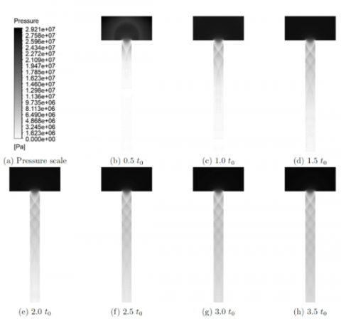
To complete the flow analysis another simulation was set up in ANSYS CFX v.18.1 trying to simulate a two-gas flow with a fine mesh to capture shock waves at the outlet of the crack. The time needed to reach a steady state solution was too high and, for this reason, just the first instants of expansion are considered. In Figures 2 and 3 the results are reported. This simulation took very small time steps to converge, in the order of 10 picoseconds when the pressure wave was confined in the crack, and 1 nanosecond when the external expansion began.
Figure 2. Shock waves development (t0 = 1μs) through a 0.1mm crack
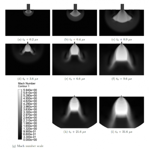
Figure 3. External jet expansion phases (t0 = 18.4 μs) from a 0.1mm crack
The first Figure represents the formation of oblique shock waves in the first millimeter of the crack, while the second Figure represents the expansion occurring at the outlet. The shape of the expansion agrees remarkably well with the study of Hamzehloo and Aleiferis [14].
Once the hypotheses were verified, the analytical model was implemented for different shapes of the possible crack: from 5 mm to 100 mm length and 0.1 mm height. The most important result was to calculate the minimum time needed to reach the critical overpressure for structures at which a security valve opens. With the maximum mass flow considered, time calculated was of the order of 30 minutes. Therefore, security procedure should be finished within this predicted time.
2.2 Compressor room studies
Second Recommendation analyzed:
Rec. 20: Review need to perform a fire explosion analysis to understand effect on the adjacent area in case of a gas leak in compressor room and provide adequate safeguards as applicable.
To fulfil Recommendation's requirements [15], two approaches are taken in account: an inert atmosphere to replicate the ship-hold and a vented solution with ventilators and extractors. These two solutions have positive elements and downsides explored in the next paragraphs.
2.2.1 Inert gas atmosphere
The main difference with the ship hold is the initial temperature that can vary depending from the climatic conditions of the ship since the room is not conditioned.
Therefore, considering that the working zones can vary from Cyprus to the Barents Sea, initial temperatures are considered from 50℃ to -20℃. For this study the analytical model developed for the hold was used successfully here too.
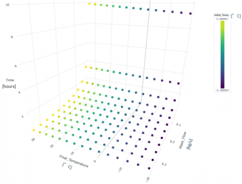
To summarize the effects of mass flow and initial room temperature in a single chart, different analysis have been performed for a step of initial temperature of 5℃, obtaining the chart in Figure 4. The chart of Figure 4 must be read starting from mass flow axis: for the lowest values, whatever is the value of initial room temperature (in blue the lowest and in yellow the higher) the time to reach critical pressure vary from 9 to 10 hours, and is slightly influenced by initial temperature (lowest value are a little faster). Conversely, for highest values of mass flow, the time to reach the critical pressure reduces significantly, and the effect of initial room temperature is negligible.
Figure 4. Relation between compressor room initial temperature, mass flow from crack, expansion time and compressor room final temperature
2.2.2 Vented room
The second approach studied is a proposed vented system, formed by four ventilators and four extractors. As a preliminary analysis, since the room planimetry had not been defined yet, three solutions were analyzed considering three different dispositions of the machines. To perform these studies, steady ANSYS CFX simulations were done considering a domain with real dimensions and with a rather coarse mesh.
This study is considered preliminary because the room planimetry was not yet defined. Results are reported below divided between the three cases:
High boundaries simulation. In this case two machines are located per every corner. This solution does not provide an efficient ventilation in the volume, since the highest velocity is confined in a tunnel connecting inlet and outlet. However, the average concentration of methane in the room is much reduced if compared with the inert gas solution, with a mean value of 1.3% instead of 10%, and with a much smaller volume of critical concentration.
Angled flow simulation. In this case inlets are located in the bottom corners of a wall and with an angled flow of 45°. Outlets are located in the opposite wall at the higher corners. This setup was studied considering that methane is lighter than air. Similarly to the previous case two machines are located in every corner used. Velocity field shows a much more ventilation occurring in the room, but this could be interrupted or modified by compressors position. In this case the concentration is much lower because the highest velocity is located in correspondence of methane source, therefore is trivial to understand that the critical concentration region is very small. The result is an average gas concentration of 0.6% instead of 1.3% as for the first proposed configuration.
All side boundary simulation. In this case inlets are located in the bottom centre of every wall in the room with an angled flow of 45°. Outlets are located in the high corner of every wall. This solution was created trying to generate a vortex in the room to improve ventilation even more. In this case the average methane concentration is again lowered with a value of 0.3%. However the concentration volume highlights a problem: if the source is located in the room centre, a significant volume of gas is confined there by the flowing air. A solution for this problem could be to modify the angle of inlet fans.
2.3 Vent mast studies
Last Recommendation analyzed:
Rec. 23: Perform gas dispersion analysis to optimize vent mast location and height to ensure gas release from vent mast will not lead to migration of gas to hazardous zone or accommodation area, which can result in a fire hazard.
The main goal of this study was to define if, after an emergency emptying of four vessels, the gas cloud would have reached dangerous zones represented by the exhaust chimney at the ship's stern and the accommodation room at the ship's bow. This study can be considered preliminary too. In fact, the piping system was not yet defined at the time these studies were performed, and therefore some assumptions had to be made. They are reported below:
Two pipe dimensions are considered: DN50 and DN100. Here only results of the DN100 case are presented since it is considered the better solution for the emptying time.
2.3.1 Results
First situation, as considered before, is a moored ship without wind. As expected, the flow just moves upwards without deviations. This can be considered a particularly safe situation.
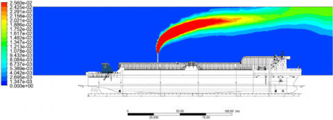
The second situation is given by maximum speed of wind, 50 kn (25.7 m/s), against the ship bow, and maximum speed of the boat of 16.5 kn (8.5 m/s), summed at inlet. In Figure 5 is reported the mass fraction contour plot with the red zone having a mass fraction of 2.56%, which is the Lower Explosive or Flammable Limit (LEL/LFL) for methane. In this case the inflammable concentration cloud is large and could reach the exhaust chimney, but, due to the high speed of gas at the vent mast, it remains above the ship. Notice that if the mass flow is maintained the same but with a lower velocity at the exit, given, for example, by the further analysis of the gas flow in piping system, the gas cloud could be much lower and therefore generate more concern.
Last case analyzed is the one with maximum rear speed of wind, 50 kn, considering the ship moored. In Figure 6 is reported the mass fraction contour plot with the red zone having a mass fraction of 2.56%. In addition, in this case the gas cloud is large but remains above the ship due to the high velocity at the exit of the vent mast. As for the previous case, if the successive studies highlight the same mass flow with a lower velocity the gas cloud could reach the ship.
To conclude the analysis of these results it is worth to note that in any case critical concentration is dissipated within a reasonable distance from the vent mast and the cloud remains high enough to not impact zones of the ship. Other wind speed conditions are not taken in account because with these directions the result would show a flow that exhibits an intermediate behavior between situations without wind and maximum wind speed. For the wind direction, instead, other possibilities were not taken in account because the wind tend to spread the cloud away from the ship. This could represent a problem for structures in harbors, but a more detailed analysis will be performed once the piping system will be completely defined.
Figure 5. Gas concentration with maximum frontal wind and ship speed
Figure 6. Gas concentration with maximum rear wind and moored ship
In this article part of the analyses needed for the safety assessment on the ship developed by the GASVESSEL project are presented.
In the hold, an inert atmosphere is used to avoid any fire issues. Some acoustic and thermal devices to spot the leakage are recommended. With the analysis presented, time identified for the security procedures should be maintained within 30 minutes to avoid any further problem. A detailed study on the jet flow has shown the rapid formation of shock waves.
In the compressor room two solutions are presented and commented, highlighting strength and weaknesses of the approaches. The most relevant factor is the possibility for the operators to enter the room with or without a breathing system. The next study to perform will be a ventilation analysis with the correct planimetry of the room and a list of possible leakage spots.
The last study, gas dispersion from the vent mast, is a preliminary analysis. The gas cloud should not reach any critical spot on the ship, such as exhaust chimneys and accommodation rooms, but an additional study, when the piping system geometry will be fully defined, is highly recommended. As another approach to the problem, although the methane mass flow is large, a combustor may be studied or, at least, taken into account.
The project has received funding from the European Union's Horizon 2020 research and innovation programme under grant agreement No 723030.
[1] European Commission. (2020). Funding programmes, Horizon. https://ec.europa.eu/programmes/horizon2020/en.
[2] Pierluigi Busetto. GASVESSEL project slides. https://ec.europa.eu/documents/06GASVESSELCompressedNaturalGasTransportSystem-ByPierluigiBusettoNavalprogettiSrl.pdf.
[3] Companies consortium. GASVESSEL. https://www.gasvessel.eu/.
[4] ABS. (2019). Compressed Natural Gas Transport System HAZID Study Report. GASVESSEL report.
[5] cEnergy. (2019). GASVESSEL-RAP-WP5-001-A01 - Reference Simulation Data.
[6] Engineering ToolBox. (2008). Methane - Thermophysical Properties. https://www.engineeringtoolbox.com/methane-d_1420.html.
[7] Bell, I.H., Wronski, J., Quoilin, S., Lemort, V. (2014). Pure and pseudo-pure fluid thermophysical property evaluation and the open-source thermophysical property library CoolProp. Industrial & engineering chemistry research, 53(6): 2498-2508. https://doi.org/10.1021/ie4033999
[8] Gianni Comini, (2000). Fondamenti di Termodinamica Applicata. SGEditoriali Padova.
[9] Ledoux, R.J., Bloomer, M., Huang, H.Z. (1986). Physics Department Massachusetts Institute of Technology Cambridge, MA 02139. In Hadronic Matter In Collision-Proceedings Of The Second International Workshop On Local Equilibrium In Strong Physics, 214.
[10] ANSYS Inc. (2009). Documentation. http://www.afs.enea.it/project/neptunius/docs/fluent/html/ug/node334.htm.
[11] Bomelburg, H.J. (1977). Estimation of gas leak rates through very small orifices and channels (No. BNWL--2223). Battelle Pacific Northwest Labs.
[12] Nederstigt, P. (2017). Real Gas Thermodynamics: and the isentropic behavior of substances, pp. 46-47. http://resolver.tudelft.nl/uuid:ee16f7e5-4251-4629-9192-8f4a2e3d599b.
[13] Gans, P.J. (1992). Joule-Thomson Expansion.
[14] Hamzehloo, A., Aleiferis, P.G. (2016). Gas dynamics and flow characteristics of highly turbulent under-expanded hydrogen and methane jets under various nozzle pressure ratios and ambient pressures. International Journal of Hydrogen Energy, 41(15): 6544-6566. https://doi.org/10.1016/j.ijhydene.2016.02.017
[15] Engineering ToolBox. (2003). Gases - Explosion and Flammability Concentration Limits. https://www.engineeringtoolbox.com/explosive-concentration-limits-d_423.html.