Alessandro d’Adamo* | Giuseppe Corda | Stefano Fontanesi | Massimo Borghi
OPEN ACCESS
Fuel cells are considered a key technology to decarbonize the power generation sector, thanks to the absence of pollutants emissions related to the direct chemical-electric energy conversion, their high global efficiency, and the possibility for on-board electricity production, overcoming the storage limits of batteries. An example of the renewed interest towards fuel cells is the research in Proton Exchange Membrane Fuel Cell (PEMFC) in the automotive sector, as a candidate alternative to fossil fuels-fed internal combustion engines (ICEs). The complex interplay of electrochemical and physical phenomena concurring in PEMFC makes their understanding and optimization a challenging task. This is a field of active research thanks to the development of advanced CAE tools, e.g., 3D-CFD simulations of non-isothermal reactive flows, in which all the relevant physics is numerically solved, allowing to identify governing mechanisms as well as system bottlenecks. Among the multiple complex aspects, the material property characterization of PEMFC components is one of the major modelling challenges for modern CAE tools. This is usually provided as a set of boundary conditions for the numerical model, having a large impact on the simulated results which is often motivated by an oversimplification of materials characteristics. Examples of commonly overlooked aspects are direction-independent thermal/flow properties for fibrous materials, the neglection on the deformed (compressed) status, and the simplified contact approach. All of these might alter the key parameters (e.g., water management) and mislead designers’ conclusions on PEMFC optimization. In this paper three-dimensional CFD simulations are used to weight the impact of orthotropic diffusion layer properties on both flow distribution and heat transfer. In the first part, a simplified test case from literature is created and used to investigate the flow convection/diffusion balance in the gas diffusion layer considering the orthotropic permeability typical of pressed fibrous layers. Differences with respect to the still widely used isotropic permeability will be assessed, and implications on channel bypass and mass transport to the catalyst layer will be provided. In the second part, the analysis moves to the use of orthotropic thermal conductivity for the fibrous gas diffusion layers, which is another commonly discarded aspect despite being well documented in literature. A critical analysis of heat transfer routes between parts of different heat capacity (membrane, diffusion layers, solid plates) and thermal field for all the components will be assessed. Finally, thermal contact resistance between adjacent pressed materials will be applied. The altered thermal pathways for heat removal will be critically analyzed, as well as the differences in temperature distribution and their implication on electricity production and water management. This hierarchical flow/thermal analysis will provide guidelines for more accurate 3D-CFD models for a deeper understanding of flow and heat dynamics in PEMFC.
PEM fuel cells, CFD, non-isotropic properties, thermal contact resistance
The more and more stringent regulations for the transportation sector are pushing next-generation Internal Combustion Engines Vehicles (ICEV) to ever growing development costs, motivated by the more complex after-treatment devices needed to comply with current and future legislations. Alongside this, the rapid diffusion of Battery Electric Vehicles (BEV) is still limited by technological constraints in specific transportation sectors (e.g. heavy-duty, off-highway, maritime, aerial). These two factors motivate the renewed interest towards Fuel Cell Electric Vehicles (FCEV), ideally complementing BEV in such sectors thanks to the on-board generation of electric power, allowing to overcome the storage/weight limits of batteries. In the automotive transportation sector, Proton Exchange Membrane Fuel Cells (PEMFC) are considered the most promising type of fuel cells, thanks to the low temperature operation and the absence of corrosive substances. Despite the use of PEMFC in industry has been known for decades, there is still a limited understanding of the complex interplay of physical/electrochemical processes governing the key phenomena for high-efficient PEMFC, as well as the role of realistic material characterization. To fulfill this knowledge gap, multi-dimensional numerical models including all the main processes allow an unprecedented comprehensive study [1-3], shedding a light on limiting phenomena and on system bottlenecks. Among the multiple components present in a PEMFC, gas diffusion layers (GDL) have multiple fundamental roles. They have the structural task of mechanically supporting the Membrane-Electrode Assembly (MEA), but they are also constituted by the materials through which species (reactants/products) flows to/from the active sites of the Catalyst Layers (CL), hence influencing the fuel/oxidizer supply rate, which becomes fundamental at high current density conditions where mass transfer rate limitations are frequent. Furthermore, being composed by carbon-based materials (papers and woven/non-woven cloth) there are optimal thermal and electrical conductors, providing a major transfer pathway for heat and electrons generates by electrochemical reactions at CL. Reviews of GDL characteristics (e.g., porosity, permeability, structure, and transport properties) are presented in [4, 5], providing a clear picture of the concurring design needs, as well as the transport mechanisms developing herein [6].
Detailed studies considering the fibrous nature of GDL are common when the focus is the material characterization [7, 8], where samples of the fiber array are modeled to derive semi-empirical or analytical modeled to be compared with experiments. However, the most common modelling approach for GDL is the so-called macro-homogeneous model, constituting in implying a homogeneous structure of equally-spaced/-sized carbon fibers to reflect their layered composition. This is not directly modelled, but the volume occupation of the solid material and the effect on flow/heat/charge transport are replicated by average (macro-homogeneous) properties, implemented as source terms in the dedicated transport equations. The reason of it is the need to preserve a lower limit to the minimum modeled scale to 1 × 102 µm.
The first objective of multi-dimensional numerical models of porous materials is to replicate their resistance to flow, i.e. the momentum conductance. In this context, the hypotheses of low Reynolds number, constant density, single-phase fluid and steady-state flow, the Darcy equation is used to bundle the absolute material permeability in the i-direction $K_{i}$[m2] to the incoming flow with $u_{i}$ velocity and molecular viscosity $\mu$ , as in Eq. (1). This is implemented in the code via user-coding.
$\frac{d p}{d x_{i}}=\frac{\mu}{K_{i}} u_{i}$ (1)
The mentioned low-Reynolds hypothesis is the foundation of the linear flow rate/pressure differential relationship expressed by Eq. (1), and it is questioned in studies regarding the flow regime in GDL Pharoah [9] for which non-dimensional numbers are proposed Zeng et al. [10] and Feser et al. [11] to weight the relevance of a non-linear (inertial) term to be added to the Darcy equation (Darcy-Forchheimer equation).
The second objective for multi-dimensional flows in GDL is related to their specific fabrication, i.e. their largely non-isotropic (layered) composition. To this aim, models should be able to consider the differentiated direction-dependent flow permeability. In particular, the random orientation of carbon planes induces similar permeability values for the in-plane direction $\left(K_{\|}\right)$, whereas a much-decreased permeability is found for the through-plane direction $\left(K_{\perp}\right)$. The permeability anisotropy in GDL is one of the fundamental aspects of interdigitated flow design [12], where all the flow is forced into the porous material via channel obstruction. This flow arrangement emphasizes the need of an exact characterization of through- and in-plane permeabilities, whose accurate modelling is a mandatory requirement to accurately predict flow intensity in GDL and pressure losses.
Empirical observations and material-scale models have been used to derive large-scale macroscopic correlations for $K_{\|} \text {and } K_{\perp}$. A periodic geometry-based model was proposed in [7], allowing to relate the porosity to the equally-sized fibers distance and to their diameter. The model is composed of distributed normal and parallel layers and blending techniques were proposed to derive global normal and parallel permeabilities. As for $K_{\perp}$, an analytical solution function of the idealized fiber diameter d was derived in Tamayol et al. [8] and validated against normal flow tests. A similar method was followed for $K_{\|}$ [13], proposing an algebraic correlation for the parallel permeability. The proposed forms for $K_{\perp}$ and $K_{\|}$ are both proportional to $d^{2}$ and they asymptotically enclose the measured permeabilities for uniformly oriented porous materials (normal and parallel to the incoming flow, respectively). In particular, $K_{\perp}$ is systematically lower than $K_{\|}$ and with all weighting techniques lie in-between, with the volume-weighting method granting the best accuracy on a porosity range $\varepsilon=0.5-0.9$ of interest. The model was extended in [8] to account for the porosity reduction due to both GDL compression and ionomer addition, leading to a permeability reduction. Tomadakis and Robertson [14] used an analogy between electrical current and fluid flow and proposed a permeability model again function of $d^{2}$. A further confirmation of the functional relationship with $d^{2}$ is present in the Van Doormaal and Pharoah [15] study and reinforced in Tamayol et al. [7] by the extension of the equally-spaced structure to three-dimensional materials. Gostick et al. [16] measured several GDL samples in both normal and parallel configurations, fitting the measured permeability with the Carman-Kozeny equation and highlighting the ever-present deviation between samples, which could be useful to outline a permeability sensitivity (average deviation 4.7% for normal permeability) applicable to macro-homogeneous models. A similar testing campaign was carried out by Gurau et al. [17], where $K_{\perp}$ and $K_{\|}$ of various GDL samples confirmed the higher in-plane permeability by a factor larger than 2. Feser et al. [18] measured $K_{\|}$ for several GDL (woven, non-woven and carbon type) using a radial flow technique, indicating $K_{\|} \sim 1 \times 10^{-11} m^{2}$ for all GDL, although sensible type-to-type variation is to be considered. Similar conclusions are found in [9, 19], although the non-systematic indication of $K_{\perp}$ and $K_{\|}$ is still present in this kind of studies.
A similar modelling challenge for GDL regards heat transfer, developing in both solid and fluid phases in a porous material. Their thermal conductivity properties constitute a network of parallel resistances, although the higher conductivity of carbon shifts the dominant role to solid-phase heat conduction. Porous materials are characterized to provide a bundled “effective” thermal conductivity $\lambda$ [W m-1 K-1], which can be measured or analytically derived, and which determines the rate of heat dissipation from the active CL surface to cooled BPP.
The layered fibrous nature of GDL has a similar effect on thermal conductivity than that discussed for flow resistance, as in in-plane conductivity ($\lambda_{\|}$) is much higher than the through-plane value ($\lambda_{\perp}$). This is motivated by the analogy between momentum and heat transport. Heat diffuses easily along the carbon fibers direction, whereas the intra-fiber heat transfer is mediated by pressed localized contacts, hence explaining the difference in the preferential heat dissipation pathway. This motivates the importance of using orthotropic thermal conductivity for GDL in multi-dimensional models if the correct heat dissipation contributions are to be predicted, using correlation from experiments or analytical models.
In Sadeghi et al. [20] and Sadeghi et al. [21] a basic cell unit was proposed to analytically determine $\lambda_{\perp}$q of GDL, including multiple heat transfer mechanisms: fiber-to-fiber Hertzian contact for compressed media, bulk solid phase conductivity and gas phase heat conduction. The thermal resistance network model confirmed the dominant role of the inter-fibers contact resistance on the other heat transfer mechanisms and its reduction for high compressive loads. The model was extended in Sadeghi et al. [22] including experimentally measured probability functions of aspect ratio and contact angle distribution for two GDL, confirming that the random fibers orientation can be approximated in a sample unit cell model by an orthogonal arrangement. A practical expression for $\lambda$ is the Dagan equation [23], based on solid/fluid thermal conductivities and material porosity $\mathcal{E}$.
Moreover, an accurate heat transfer modelling must include the Thermal Contact Resistance (TCR [m2 K W-1]) present at the interfaces of GDL with membrane and BPP. The heat transfer loss between separate conductive parts was analytically studied by Sadeghi et al. [24] under various compressive loads. They underlined the superficial nature of TCR, different in concept than the global thermal conductivity of the bulk porous medium. Test acquisition and model prediction based on a parallel network of contact spots agreed in indicating the inter-component contact resistance contributing by 65 - 90% to the overall thermal resistance, mainly due to the limited effective contact area (approx. 1% of the nominal cross-sectional area). Experimental measurements by Khandelwal and Mench [25] confirmed the relevance of TCR in a 1D heat transfer testing arrangement.
In this work the impact of using complex properties for GDL characterization is studied using 3D-CFD models. In the first part the impact of orthotropic K is assessed with respect to standard isotropic models, with focus on inter-channel by-pass flow rate in serpentine-type gas distributors and of the effect on reducing the flow-inactive under-rib regions. In the second part, heat transfer is studied applying orthotropic $\lambda$ for GDL and including TCR at the solid-solid GDL pressed contacts. The effect on global results and on field distribution is critically discussed, and guidelines on modelling practices for these properties are provided.
A straight-channel half-cell model from Tabuchi et al. [26] and D’Adamo et al. [27] is considered to weight the effect of material properties on the resulting flow distribution and heat transfer routes. The half-cell assumption is introduced due to the common symmetry of material properties and of gas distributors between the anodic/cathodic sides.
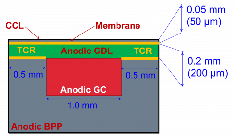
A straight channel with 0.5x1 mm cross section faces a 200 μm thick GDL and a 50 μm thick membrane which includes the CL thickness on both sides. An axial length of 10 mm is considered. A graphite Bipolar Plate (BPP) is added to complete the cell assembly. In Figure 1 all the parts and the main dimensions are reported.
A numerical grid is created using hexahedral structured cells for GDL/membrane and polyhedral cells for Gas Channel (GC)/BPP, with conformal mesh at interfaces allowing continuity of variables and their conjugate coupling (e.g. for heat transfer between material with different properties). The membrane and GDL thicknesses are discretized using 8 cell layers in the cross-direction each, and the total number of cells is 260’000. The multi-part model generation and the grid creation have been carried out with STAR-CCM+ 2020.2 licensed my SIEMENS DISW, which was also used for CFD simulations. The study focus on flow permeability and heat transfer in porous materials allows to use a steady-state, single-phase and laminar flow assumptions. Also, heat sources substitute the heat generation by electrochemical reactions, which for this reason are not included in the present model.
Figure 1. Sketch of model parts and main dimensions. TCR are applied to yellow-marked interfaces
In the first part of the study, three different flow regimes are analysed by imposing three levels of outlet/inlet pressure differential (Δp=-50 Pa, -100 Pa and -500 Pa), corresponding to average inlet Reynolds numbers of Re=73, 129 and 473, respectively. For each flow condition, the absolute in-plane permeability of the GDL material is varied from being equal to the through-plane value (hence implying an isotropic permeability) to being one order of magnitude higher, and the impact on flow distribution is discussed both analysing the lateral flow rate to GDL outlets (representing channel by-pass in a serpentine-type distributor) and wall shear stress on the CL surface. To mimic the driving force operated by adjacent low-pressure channels, the same Δp is applied both at the channel outlet section and at the lateral GDL sides.
In the second part a temperature profile is imposed to the opposite side of the membrane, i.e. the cathodic CL where electrochemical reactions occur, and the anodic BPP endplate (lower end in Figure 1) is kept at the same temperature as the inlet fluid (350 K) to replicate the effect of a cooling circuit. Similarly, the GDL in-plane thermal conductivity is changed from being equal to the through-plane one (isotropic) to being one order of magnitude higher, representing the favoured heat transfer of fibrous material in the fibers’ direction than through the inter-fibre contact spots. Finally, the inclusion of a thermal contact resistance at GDL/membrane and BPP/GDL interfaces is discussed both in terms of temperature field distribution and of thermal power dissipated though the conductive BPP.
In this Section the results of the two analyses will be presented, and the practical implications of using complex material properties on the large-scale PEMFC results will be critically discussed.
3.1 Effect of GDL permeability
The analysis of GDL permeability is carried out by imposing three flow regimes (Re=73, 129 and 473, respectively) and by changing the in-plane GDL permeability on three levels ($K_{\|}=5 \times 10^{-12} \mathrm{~m}^{2}, 1 \times 10^{-11} \mathrm{~m}^{2}$ and $5 \times 10^{-11} m^{2}$, respectively), for a total of 9 cases listed in Table 1. These values are typical of GDL with $\varepsilon=0.7$ porosity, as the one considered in the model.
Table 1. List of cases for GDL permeability analyses
|
Case Name |
Reynolds Number |
Absolute Permeability [m2] |
|
Case 1Table size |
73 |
$\begin{gathered} |
|
Case 2 |
73 |
$\begin{gathered} |
|
Case 3 |
73 |
$\begin{gathered} |
|
Case 4 |
129 |
$\begin{gathered} |
|
Case 5 |
129 |
$\begin{gathered} |
|
Case 6 |
129 |
$\begin{gathered} |
|
Case 7 |
473 |
$$\begin{gathered} |
|
Case 8 |
473 |
$\begin{gathered} |
|
Case 9 |
473 |
$\begin{gathered} |
In Figure 2 the flow rate distribution for each case is reported, representing the mass flow rate percentage at the outlet channel section. If no flow rate by-pass was present (non-porous GDL) it would read 100%, and for all cases the complement to 100% is the flow rate fraction escaping the channel via the permeable GDL and directly flowing to adjacent gas channels. The practical implication of this is that the under-rib region benefits from an ever more relevant flow convection, facilitating reactants delivery and product water removal. This corresponds to improving the electrochemical activity of a typically under-used catalyst layer area. From a modelling perspective, this better replicates the plane-oriented carbon layers composing GDL, whose random orientation in the cell plane induces a similarly high flow permeability in the plane directions.
A trend of increasing by-pass flow rate for higher in-plane permeability is observed for all the tested flow regimes, indicating a 25-30% of total flow rate escaping through the porous GDL, despite its relevance marginally reduces for high Re conditions. The use of isotropic properties $\left(K_{\|}=K_{\perp}=5 \times 10^{-12} \mathrm{~m}^{2}\right)$ would have largely underpredicted this effect, with more than 90% of the fluid flowing directly to the channel outlet, thus underestimating the entity of the flow in porous diffusion layers.
In Figure 3 the velocity field is represented on GC and GDL sections, visually confirming the entity of higher flow by-pass for cases with higher $K_{\|}$ and highlighting the non-negligible flow in under-rib areas. The well-established literature basis on this aspect indicates that orthotropic permeability with $K_{\|} \gg K_{\perp}$ is to be applied in multi-dimensional models, and that Case 3-9 are considered a more accurate representation of the actual flow behaviour.
Figure 2. Flow rate percentage at GC outlet, with complement to 100% being the by-pass flow rate through GDL
Figure 3. Velocity field on GC and GDL sections for Case 1-3 (top) and Case7-9 (bottom)
One of the major aspects to be observed is the degree of flow interaction with the CL surface, being representative of the reactants supply effectiveness of the cell assembly. Despite in this study electrochemical reactions are not included, the efficiency of mass transport and its uniformity on the CL surface are analysed though the Wall Shear Stress (WSS), defined as in Eq. (2). This allows to spatially identify areas of active transport of reactants by near-wall flow convection, as well as inactive regions whose only transport mechanism is wall-normal flow diffusion. The WSS and its spatial distribution are a consequence of the GC and GDL design, hence they can be relevantly altered with different distributors or GDL designs.
$\tau_{w[P a]}=\left.\mu \frac{\partial U_{i}}{\partial x_{j}}\right|_{x_{j}=0}$ (2)
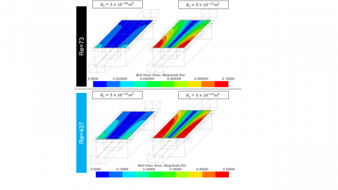
It can be observed in Figure 4 that for increasing in-plane permeability, higher WSS is predicted in under-rib regions, especially in proximity of the inlet section. This indicates them as actively reacting areas despite being far from the reactants-delivering channels. It also underlines how the use of isotropic permeability would largely underestimate this positive effect.
Figure 4. WSS field on CL for Case 1-3 (top) and Case 7-9 (bottom)
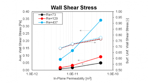
Quantitative measurements of WSS are reported in Figure 5, showing both the mean WSS value on the active surface and its spatial uniformity ($S U_{\tau_{w}}$), defined as in Eq. (3). It is used as a uniformity index for the WSS and considers the surface average WSS on the CL ($\overline{\tau_{w}}$) and the local value $\tau_{w, i}$ on the i-th face having area $A_{i}$. Values of $S U_{\tau_{w}}$ as close as possible to unity are desired, indicating a uniform wall shear stress on the entire CL surface and maximizing the catalyst usage. It is observed that for higher in-plane permeability, both the mean WSS and its uniformity increase, further emphasising the impact of using complex realistic-like properties for GDL on the reactants supply for reactions.
$S U_{\tau_{w}[-]}=1-\frac{\sum_{i}\left|\tau_{w, i}-\overline{\tau_{w}}\right| \cdot A_{i}}{2 \cdot\left|\overline{\tau_{w}}\right| \cdot \sum_{i}^{m} A_{i}}$ (3)
Figure 5. Surface average WSS at CL (left scale) and its uniformity index (right scale) as a function of in-plane permeability for the 9 cases
3.2 Effect of GDL thermal conductivity and contact resistance
In the second part of the study, the focus moves to the heat dissipation through conductive solid parts. The major heat sources in PEMFC are electrochemical reactions and ohmic resistance, with these last i) considered of reduced entity in highly electrical-conductive materials and ii) not included in this study. Therefore, to mimic electrochemically generated heat, a typical temperature profile is applied on the opposite side of the membrane (i.e. at cathodic catalyst layer, CCL). Thermal conductivity for the membrane is $\lambda_{\text {mem }}=0.5$ W m-1 K-1, while for the graphite BPP a $\lambda_{\text {mem }}=20$ W m-1 K-1value is used. For both membrane and BPP an isotropic value is justified for $\lambda$, given their different structure than diffusion media. As for the GDL, the implication of the fiber-oriented nature discussed for flow permeability maintains a similar validity also for heat transfer, as heat diffusion along carbon fibers is much more effective than inter-fibers transport, which is mediated by isolated contact areas. It is to be noted that heat transfer proceeds also along the fluid continuum, although its contribution is marginal compared to the solid-phase process. Therefore, the effect of the fiber-oriented GDL fabrication is considered moving from an equal though-/in-plane conductivity (e.g. isotropic $\lambda$) to a one order of magnitude higher in-plane conductivity $\left(\lambda_{\|} \gg \lambda_{\perp}\right)$.
Moreover, the multi-part composition of the cell assembly has implications on heat transfer routes, i.e. GDL is a separate component than membrane and BPP. Parts are assembled and clamped to a sealing pressure (typically $p_{\text {seal }}=1.0$ Mpa) which facilitates heat conduction between parts, reducing the ever-present TCR between the pressed parts. This is another overlooked aspect in 3D-CFD simulations, whose effect is included and discussed in this study. The list of simulations is reported in Table 2.
A typical temperature profile of CCL section is derived from [27], aiming at obtaining no heating far from the channel region (i.e. T=350 K) and a maximum temperature increase along the channel axis of 100 K, using a modified Gaussian distribution as in Eq. (4). Despite this probably overestimates the reaction heating, it is useful to highlight the different heat dissipation mechanisms to the BPP endplate, which is maintained at 350 K to replicate the presence of a cooling circuit. In Figure 6 the resulting temperature distribution imposed at CCL is illustrated.
Table 2. Simulations list for GDL heat transfer analysis
|
Case Name |
Thermal Conductivity [W m-1 K-1] |
Thermal Contact Resistance [m2 K W-1] |
|
Case 1Table size |
$\lambda_{\perp}=1.8, \lambda_{\|}=1.8$ (isotropic) |
$T C R=0$ |
|
Case 2 |
$\lambda_{\perp}=1.8, \lambda_{\|}=1.8$ |
$T C R=0$ |
|
Case 3 |
$\lambda_{\perp}=1.8, \lambda_{\|}=1.8$ |
$T C R=3 \times 10^{-4}$ |
$\begin{gathered}
T(x)_{[K]}=350+0.05 \frac{1}{2 \times 10^{-4} \sqrt{2 \pi}} \exp [-0.5 \\
\left.\cdot\left(\frac{x}{2 \times 10^{-4}}\right)^{2}\right]
\end{gathered}$ (4)
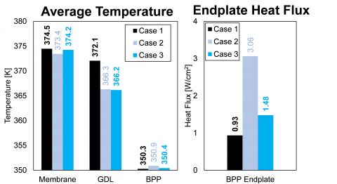
The mean (volume averaged) part temperature is reported for the three cases in Figure 7. The use of realistic orthotropic $\lambda$ values for the GDL (i.e. from Case 1 to Case 2) leads to a visible decrease in the GDL mean temperature, motivated by the facilitated lateral heat transfer pathway to solid BPP. This is testified also by the increase in the thermal flux measured at the BPP endplate (+227%). This is expected as the heat transfer pathway among components follows the membrane-GDL-BPP path, hence constituting a series network. The introduction of the TCR (i.e. from Case 2 to Case 3) does not significantly alter the mean temperature of any component, although it hampers the heat dissipation to the BPP endplate, which however is higher than in Case 1 (+58%) where both accurate $\lambda$ definition and TCR were omitted. For all the cases the membrane temperature remains similar due to the boundary condition adopted (temperature distribution applied to the membrane-adjacent CCL).
Figure 6. Temperature field imposed at CCL
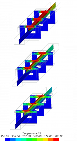
Moving to the temperature distribution reported in Figure 8 for the three cases, it further highlights the relevance of both using non-isotropic $\lambda$ values for porous GDL and of the inclusion of TCR at the interfaces of pressed GDL with membrane/BPP.
Figure 7. Mean (volume average) part temperature (left graph) and surface average heat flux at BPP endplate (right graph) for all the cases
Moving from Case 1 to Case 2 (change to orthotropic $\lambda$), it is noted how the higher $\lambda_{\|}$ value favours the in-plane heat transport, thus reducing thermal gradients on the GDL and replicating the effect of the plane-oriented carbon fibres. When TCR is added (Case 3), the heat transfer from/to the GDL is obstructed: the result is that an even more uniform heat distribution in the GDL is observed.
Figure 8. Temperature distribution on GC and GDL sections for Cases 1 (top), 2 (middle) and 3 (bottom)
The analysis of the largely different temperature distribution, combined with the effect on mean parts temperature, and of the dissipated heat flux form the conclusion that it is of utmost importance to include accurate and experimentally-derived non-isotropic material properties for GDL, as typical of series-arranged thermal resistances.
The development and industrialization of Proton Exchange Membrane Fuel Cells is considered a key route for a fully sustainable mobility and power generation. This is made possible by their high efficiency, the absence of pollutant emissions and the high energy density. However, the lack of a complete comprehension of the interplaying physical and chemical processes developing in PEMFC is still not acquired, reducing the possibilities of a virtual-based design improvements. An example of this limited knowledge is the still widespread use of isotropic properties for materials in PEMFC, which is often overlooked but which becomes unacceptable when these are applied to GDL, whose fibrous layered composition induces orders of magnitude of anisotropy between in-plane and through-plane directions. An incorrect characterization of this key component alters all the main transport rates (flow permeability, heat transfer), thus limiting the role of simulations.
In this study the effect of complex material characterization for GDL on 3D-CFD simulation of PEMFC is assessed. In the first part the role of the in-plane permeability modeling is observed, while in the second part the focus moves to the analysis of in-plane thermal conductivity and of the presence of a contact thermal resistance. The results show that:
|
BEV |
battery electric vehicles |
|
BPP |
bipolar plate |
|
CAE |
computer aided engineering |
|
CCL |
cathodic catalyst layer |
|
CFD |
computational fluid dynamics |
|
CL |
catalyst layer |
|
FCEV |
fuel cell electric vehicle |
|
GC |
gas channel |
|
GDL |
gas diffusion layer |
|
ICEV |
internal combustion engine vehicles |
|
K |
absolute permeability, m2 |
|
MEA |
membrane-electrode assembly |
|
PEMFC |
proton exchange membrane fuel cell |
|
SU |
surface uniformity, - |
|
TCR |
thermal contact resistance, K m2 W-1 |
|
WSS |
wall shear stress, Pa |
|
Greek symbols |
|
|
$\lambda$ |
thermal conductivity, W m-1 K-1 |
|
$\mu$ |
dynamic viscosity, Pa s |
|
$\tau$ |
shear stress, Pa |
|
Subscripts |
|
|
w |
wall |
|
$\| / \perp$ |
in-plane / through-plane |
[1] Berning, T., Lu, D.M., Djilali, N. (2002). Three-dimensional computational analysis of transport phenomena in a PEM fuel cell. Journal of Power Sources, 106(1-2): 284-294. https://doi.org/10.1016/S0378-7753(01)01057-6
[2] Riccardi, M., d’Adamo, A., Vaini, A., Romagnoli, M., Borghi, M., Fontanesi, S. (2020). Experimental validation of a 3D-CFD model of a PEM fuel cell. In E3S Web of Conferences, 197: 05004. https://doi.org/10.1051/e3sconf/202019705004
[3] Wang, C.Y. (2004). Fundamental models for fuel cell engineering. Chemical Reviews, 104(10): 4727-4766. https://doi.org/10.1021/cr020718s
[4] Zamel, N., Li, X. (2013). Effective transport properties for polymer electrolyte membrane fuel cells–with a focus on the gas diffusion layer. Progress in Energy and Combustion Science, 39(1): 111-146. https://doi.org/10.1016/j.pecs.2012.07.002
[5] Cindrella, L., Kannan, A.M., Lin, J.F., Saminathan, K., Ho, Y., Lin, C.W., Wertz, J. (2009). Gas diffusion layer for proton exchange membrane fuel cells—A review. Journal of Power Sources, 194(1): 146-160. https://doi.org/10.1016/j.jpowsour.2009.04.005
[6] Weber, A.Z., Borup, R.L., Darling, R.M., Das, P.K., Dursch, T.J., Gu, W. (2014). A critical review of modeling transport phenomena in polymer-electrolyte fuel cells. Journal of the Electrochemical Society, 161(12): F1254. https://doi.org/10.1149/2.0751412jes
[7] Tamayol, A., Bahrami, M. (2011). In-plane gas permeability of proton exchange membrane fuel cell gas diffusion layers. Journal of Power Sources, 196(7): 3559-3564. https://doi.org/10.1016/j.jpowsour.2010.11.109
[8] Tamayol, A., McGregor, F., Bahrami, M. (2012). Single phase through-plane permeability of carbon paper gas diffusion layers. Journal of Power Sources, 204: 94-99. https://doi.org/10.1016/j.jpowsour.2011.11.084
[9] Pharoah, J.G. (2005). On the permeability of gas diffusion media used in PEM fuel cells. Journal of Power Sources, 144(1): 77-82. https://doi.org/10.1016/j.jpowsour.2004.11.069
[10] Zeng, Z., Grigg, R. (2006). A criterion for non-Darcy flow in porous media. Transport in Porous Media, 63(1): 57-69. https://doi.org/10.1007/s11242-005-2720-3
[11] Feser, J.P., Prasad, A.K., Advani, S.G. (2006). On the relative influence of convection in serpentine flow fields of PEM fuel cells. Journal of Power Sources, 161(1): 404-412. https://doi.org/10.1016/j.jpowsour.2006.04.129
[12] Um, S., Wang, C.Y. (2004). Three-dimensional analysis of transport and electrochemical reactions in polymer electrolyte fuel cells. Journal of Power Sources, 125(1): 40-51. https://doi.org/10.1016/j.jpowsour.2003.07.007
[13] Tamayol, A., Bahrami, M. (2010). Parallel flow through ordered fibers: An analytical approach. Journal of Fluids Engineering, 132(11). https://doi.org/10.1115/1.4002169
[14] Tomadakis, M.M., Robertson, T.J. (2005). Viscous permeability of random fiber structures: comparison of electrical and diffusional estimates with experimental and analytical results. Journal of Composite Materials, 39(2): 3-188. https://doi.org/10.1177/0021998305046438
[15] Van Doormaal, M.A., Pharoah, J.G. (2009). Determination of permeability in fibrous porous media using the lattice Boltzmann method with application to PEM fuel cells. International Journal for Numerical Methods in Fluids, 59(1): 75-89. https://doi.org/10.1002/fld.1811
[16] Gostick, J.T., Fowler, M.W., Pritzker, M.D., Ioannidis, M.A., Behra, L.M. (2006). In-plane and through-plane gas permeability of carbon fiber electrode backing layers. Journal of Power Sources, 162(1): 28-238. https://doi.org/10.1016/j.jpowsour.2006.06.096
[17] Gurau, V., Bluemle, M.J., De Castro, E.S., Tsou, Y.M., Zawodzinski Jr, T.A., Mann Jr, J.A. (2007). Characterization of transport properties in gas diffusion layers for proton exchange membrane fuel cells: 2. Absolute permeability. Journal of Power Sources, 165(2): 93-802. https://doi.org/10.1016/j.jpowsour.2006.12.068
[18] Feser, J.P., Prasad, A.K., Advani, S.G. (2006). Experimental characterization of in-plane permeability of gas diffusion layers. Journal of Power Sources, 162(2): 226-1231. https://doi.org/10.1016/j.jpowsour.2006.07.058
[19] Taira, H., Liu, H. (2012). In-situ measurements of GDL effective permeability and under-land cross-flow in a PEM fuel cell. International Journal of Hydrogen Energy, 37(18): 3725-13730. https://doi.org/10.1016/j.ijhydene.2012.03.030
[20] Sadeghi, E., Bahrami, M., Djilali, N. (2008). Analytic determination of the effective thermal conductivity of PEM fuel cell gas diffusion layers. Journal of Power Sources, 179(1): 0-208. https://doi.org/10.1016/j.jpowsour.2007.12.058
[21] Sadeghi, E., Bahrami, M., Djilali, N. (2008). A compact thermal resistance model for determining effective thermal conductivity in the fibrous gas diffusion layers of fuel cells. In Heat Transfer Summer Conference, 48470: 439-447. https://doi.org/10.1115/HT2008-56158
[22] Sadeghifar, H., Bahrami, M., Djilali, N. (2012). A statistically based thermal conductivity model for PEMFC gas diffusion layers. In International Conference on Fuel Cell Science, Engineering and Technology, 44823: 129-141. https://doi.org/10.1016/j.jpowsour.2013.01.086
[23] Dagan, G. (2012). Flow and transport in porous formations. Springer Science & Business Media. https://doi.org/10.1007/978-3-642-75015-1
[24] Sadeghi, E., Djilali, N., Bahrami, M. (2011). Effective thermal conductivity and thermal contact resistance of gas diffusion layers in proton exchange membrane fuel cells. Part 1: Effect of compressive load. Journal of Power Sources, 196(1): 246-254. https://doi.org/10.1016/j.jpowsour.2010.06.039
[25] Khandelwal, M., Mench, M.M. (2006). Direct measurement of through-plane thermal conductivity and contact resistance in fuel cell materials. Journal of Power Sources, 161(2): 1106-1115. https://doi.org/10.1016/j.jpowsour.2006.06.092
[26] Tabuchi, Y., Shiomi, T., Aoki, O., Kubo, N., Shinohara, K. (2010). Effects of heat and water transport on the performance of polymer electrolyte membrane fuel cell under high current density operation. Electrochimica Acta, 56(1): 352-360. https://doi.org/10.1016/j.electacta.2010.08.070
[27] D'Adamo, A., Riccardi, M., Locci, C., Romagnoli, M., Fontanesi, S. (2020). Numerical Simulation of a High Current Density PEM Fuel Cell (No. 2020-24-0016). SAE Technical Paper. https://doi.org/10.4271/2020-24-0016