Surnam Sonia Longo* | Maurizio Cellura | Maria Anna Cusenza | Francesco Guarino | Ilaria Marotta
OPEN ACCESS
This paper aims at assessing the embodied energy and greenhouse gas emissions (GHGs) of two building envelopes, designed for a two floors semi-detached house located in the Central Italy.
The analysis is performed by applying the Life Cycle Assessment methodology, following a from cradle-to-gate approach.
Fixtures (windows and doors), external and internal opaque walls, roof and floors (including interstorey floors) make the building envelopes. Their stratigraphy allows for achieving the thermal transmittance values established in the Italian Decree on energy performance of buildings. The two examined envelopes differ only for the insulation material: extruded expanded polystyrene (XPS) or cellulose fibers.
The results shows that the envelope using cellulose fibers has better performance than that using XPS: it allows for reducing the embodied energy and the GHGs of about 13% and 9.3%, respectively.
A dominance analysis allows to identify the envelope components responsible of the higher impacts and the contribution of the insulating material to the impacts.
The study is part of the Italian research “Analysis of the energy impacts and greenhouse gas emissions of technologies and components for the energy efficiency of buildings from a life cycle perspective” funded by the Three-year Research Plan within the National Electricity System 2019-2021.
building envelope, embodied energy, greenhouse gas emission, life cycle assessment
The building sector is one of the most energy and carbon intensive in industrialized countries; in 2019, it was responsible of about 35% of global total final energy consumption and 38% of the total energy-related CO2 emissions [1].
Thus, the topic of reducing energy consumption and CO2 emissions in buildings gained an increasing interest in the last years.
Most of the existing energy and environmental policies often focus on actions aimed at reducing the buildings operating energy and emissions, i.e. the use of insulation materials for reducing the building thermal transmittance and then the energy required for the building air-conditioning.
However, another contribution must be taken into account, which is the impact (energy consumption or pollutant emissions) caused during the resources extraction, materials construction, building maintenance and demolition and waste treatments. This hidden impact is known as “embodied” in the scientific literature. Its contribution to the total impacts is usually about 10-25% for traditional buildings and increases for low-energy of nearly-zero energy buildings [2, 3]. Thus, it cannot be considered negligible.
The Life Cycle Assessment (LCA) is a reliable and scientifically based methodology usually applied for calculating the embodied impacts of products and services.
In this context, the study presented in this paper applies the LCA for assessing the embodied and the greenhouse gas emissions (GHGs) of two building envelopes characterized by a different insulation material, designed for a two floors semi-detached house.
The building examined is a new residential two floors semi-detached house located in the Central Italy (Climatic zone D, degree days 1415). The total net surface of the building is 611.12 m2 (unheated ground floor: 155.24 m2; first floor: 151.54 m2; second floor: 152.50 m2; unheated attic: 151.84 m2).
The ground floor includes two garages and the entrance floor. Two independent apartments occupy the first (air conditioned surface: 139.17 m2) and second floor (air conditioned surface: 140.13 m2).
The building envelope is examined considering two scenarios that only differ for the insulation material: extruded expanded polystyrene - XPS (Scenario A) or cellulose fibers (Scenario B).
Table 1 shows the stratigraphy of the two scenarios examined, which only differ for the insulation typology and thickness. Each stratigraphy is designed for achieving thermal transmittance values lower than that established in the Italian Decree on energy performance of buildings [4] (Table 2).
The windows have a double glass with argon in the cavity (4/16/4) and a Solar Heat Gain Coefficient equal to 0.589 with visible transmittance equal to 0.706.
The areas of the opaque and glazed surfaces, for each vertical orientation, are showed in Table 3.
Table 1. Stratigraphy of the building envelope
|
Component of the building envelope |
Scenario A and B |
|
RoofTable size |
Wood, insulation, waterproofing membrane, tilescan be |
|
External opaque walls |
Gypsum-plaster, hollow brick, air, hollow brick, insulation, gypsum-plaster |
|
Internal opaque walls |
Gypsum-plaster, hollow brick, gypsum-plaster |
|
Base floor |
Ceramic tiles, cement mortar, reinforced concrete |
|
Interstorey floors |
Ceramic tiles, cement mortar, reinforced concrete, insulation, gypsum-plaster |
Table 2. Thermal transmittance values (Usc= value for each scenario; Uref= reference value of the Italian Decree)
|
Component of the building envelope |
Usc [W/(m2K)] |
Uref [W/(m2K)] |
|
RoofTable size |
0.20 |
0.29 |
|
External opaque walls |
0.21 |
0.26 |
|
Internal opaque walls |
0.25 |
0.29 |
|
Base floor |
0.25 |
0.26 |
|
Interstorey floors |
1.40 |
1.8O |
Table 3. Thermal transmittance values (Usc= value for each scenario; Uref= reference value of the Italian Decree)
|
Orientation |
Opaque surfaces [m2] |
Glazed surfaces [m2] |
|
EastTable size |
30.82 |
9.90 |
|
South |
31.75 |
7.20 |
|
West |
35.32 |
5.40 |
|
North |
38.94 |
1.05 |
3.1 Goal and scope definition
The LCA methodology is applied according to the international standards of the ISO 14040 series [5, 6] to assess the embodied energy and GHGs emissions of the case study described in Section 2, considering two scenarios (A and B), to identify the envelope components responsible of the higher impacts and to evaluate the contribution of the insulating material on the total impacts.
The results of the analysis are referred to the whole building envelope, selected as functional unit. The impacts of the building envelope components are calculated following a “from cradle to gate” approach, including the extraction and transformation of raw materials, their transport to the manufacturing sites and the manufacturing processes of the above components [7, 8].
The Cumulative Energy Demand method [9] is applied for calculating the embodied energy (renewable and non-renewable), while the EN 15804 +A2 Method V1.00 (based on [10]) is used for accounting the GHGs emissions.
3.2 Life Cycle Inventory
The Life Cycle Inventory consists in the collection and elaboration of background and foreground data for modelling the building envelope components.
Foreground data, including the materials and relative quantities used for the manufacture of each envelope component, are taken from technical documents of the building project. Table 4 summarizes the envelope components included in the analysis and the relative surfaces for both the examined scenarios. Some few differences can be observed in the two scenarios, due to the different thickness of the insulation needed to obtain the transmittance values indicated in Table 2.
Background data, describing the eco-profiles of materials and energy sources used for the manufacturing of the system components are referred to the environmental database Ecoinvent 3.6 [11] and describe the Italian context when possible, or the European context alternatively. The background data include the energy and environmental burdens due to the raw materials supply, the transports, the manufacturing of the envelope components and, in some cases, the treatment of the process wastes. Thus, they are representative of the selected system boundaries (“from cradle-to gate”).
Table 4. Building envelope components and relative surfaces
|
Component of the building envelope |
Scenario A [m2] |
Scenario B [m2] |
|
Roof |
156.25 |
156.45 |
|
Interstorey floors |
536.16 |
537.78 |
|
Base floor |
178.72 |
179.26 |
|
External opaque walls |
606.85 |
609.54 |
|
Internal opaque walls |
340.66 |
340.66 |
|
Windows |
58.12 |
58.12 |
|
Internal doors |
31.40 |
31.40 |
|
External doors |
9.92 |
9.92 |
|
Garage doors |
38.4 |
38.4 |
3.3 Life Cycle Impact Assessment and interpretation
The results of the LCA are recapped in Table 5. The energy embodied in the building envelope mainly comes from non-renewable energy sources: the share of embodied energy from renewable energy sources is about 18.4% in the first scenario and 21.5% in the second one.
A comparison of the two scenarios highlights that the use of the cellulose fibers as insulation allows for reducing the energy and environmental impacts of the selected functional unit of about 13% and 9.3%, respectively.
Table 5. Embodied energy and GHGs emissions of the two examined scenarios
|
Scenario/Impact category |
Embodied energy [GJ] |
GHGs emissions [ton CO2eq] |
|
Scenario ATable size |
2,570 |
159.0 |
|
Scenario B |
2,230 |
144.3 |
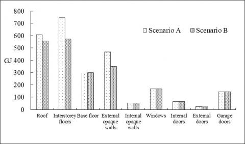
A dominance analysis, carried out to identify the envelope components responsible of the higher impacts, indicates that the impact on embodied energy (Figure 1) is mainly caused by the interstorey floors (29% for Scenario A and 25.7% for Scenario B), the roof (23.7% for Scenario A and 25.0% for Scenario B) and the external opaque walls (18.2% for Scenario A and 15.7% for Scenario B). The base floor has an incidence on the energy impact of about 11.6% and 13.4%, respectively for Scenario A and B, while each of the other components gives a contribution lower than 7.5%.
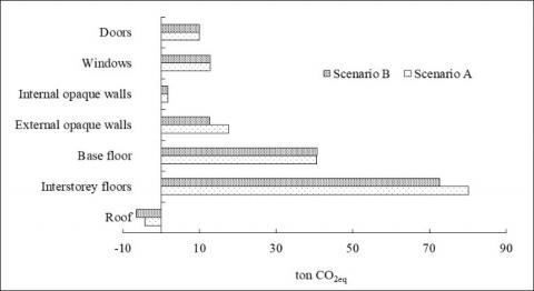
Figure 2 shows the contribution of the building envelope components to the total GHGs emissions.
Figure 1. Dominance analysis: contribution of each envelope component to the embodied energy
Figure 2. Dominance analysis: contribution of each envelope component to the GHGs emissions
The impact of the base and interstorey floors is predominant, while a negative impact is observed for the roof. This negative value comes from the wood used in the roof and, in particular, it is associated to the CO2 absorbed by the plant used for the wood manufacturing.
A detailed analysis of each envelope component in which the insulation material is used (roof, external opaque walls and interstorey floors) identifies the materials responsible of the main impact on the embodied energy and GHGs emissions and the contribution of the insulation material, as detailed in Figure 3, Figure 4 and Figure 5.
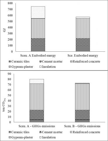
In detail, an analysis of the results for the interstorey floors (Figure 3) highlights the relevant contribution of the reinforced concrete on the embodied energy (44% for Scenario A and 58% for Scenario B) and GHGs emissions (61.4% for Scenario A and 67.9% for Scenario B). The insulation material represents about 25% of the energy impact in Scenario A and 4% in Scenario B, while its contribution to the environmental impact is about 10.6% and 1.2% for Scenario A and B, respectively.
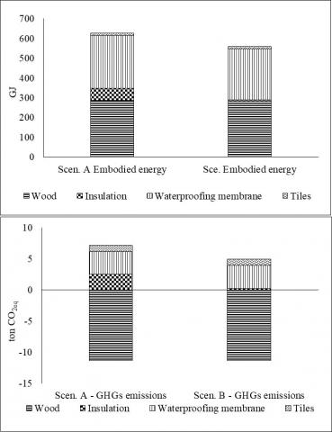
The wood and the waterproofing membrane are the main responsible of the roof embodied energy (88% in Scenario A and 97% in Scenario B), while the insulation materials causes about 9.7% and 1.3% of the embodied energy for Scenario A and B, respectively (Figure 4). In both scenarios, a negative contribution to the environmental impacts (GHGs emissions) due to wood totally offset the positive impact of the tiles, insulation and waterproofing membrane.
Figure 3. Dominance analysis: contribution of each material to the impacts of the interstorey floors
Figure 4. Dominance analysis: contribution of each material to the impacts of the roof
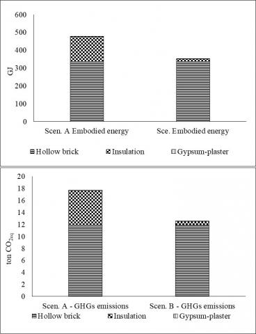
Figure 5. Dominance analysis: contribution of each material to the impacts of the external opaque walls
Focusing on the external opaque walls (Figure 5), the hollow bricks account for about 67-70% of the energy and environmental impact in Scenario A and 95% in Scenario B; the contribution of XPS and cellulose fibers is about 30-33% and 5%, respectively.
The use of the cellulose fibers instead of XPS as insulation allows for reducing the embodied energy and GHGs emissions of interstorey floors (23% and 9.3%) and external opaque walls (25% and 30%). An embodied energy reduction of about 8% is observed for the roof, which also presents a higher negative contribution for the GHGs emissions (-4.17 ton CO2eq for Scenario A and – 6.40 ton CO2eq for Scenario B).
The paper described a research aiming at comparing two building envelopes characterized by the use of different insulating materials (XPS and cellulose fibers), by applying the LCA methodology.
The results of the study suggest to prefer the use of cellulose fibers for the insulation of building, considering that this material is able to reduce the energy and GHGs emissions of the envelope if compared with XPS.
However, it is important to point out that complete analyses taking into account additional environmental impacts, e.g. ozone depletion potential, eco-toxicity, acidification potential, etc., need to be performed for correctly orienting choices in a decisional context.
Furthermore, future actions and strategies aimed at the construction of buildings with lower embodied impacts have to focus primarily on the components responsible of the main impacts, which in the examined case study are interstorey floors, roof and external opaque walls for the embodied energy and the base and interstorey floors for the GHGs emissions.
Theresults also indicate that the use of renewable materials, as ood, can have a negative impact on the emissions of greenhouse gases (impact that can become null when the end-of-life of the wood is accounted for). Thus, moving toward the use of renewable sources, both with or without energy context, can positively influence the environmental footprint of buildings and can contribute to the creation of a circular and regenerative economy.
The study is part of the Italian research “Analysis of the energy impacts and greenhouse gas emissions of technologies and components for the energy efficiency of buildings from a life cycle perspective” funded by the Three-year Research Plan within the National Electricity System 2019-2021.
|
GHGs |
Greenhouse gases |
|
LCA |
Life Cycle Assessment |
|
XPS |
Extruded expanded polystyrene |
|
Symbols |
|
|
Uref |
Limit thermal transmittance value of the Italian Decree |
|
Usc |
Thermal transmittance values of the scenario examined |
[1] Abergel, T., Dulac, J., Hamilton, I., Jordan, M., Pradeep, A. (2019). Global Status Report for Buildings and Construction—Towards a Zero-Emissions, Efficient and Resilient Buildings and Construction Sector.
[2] Beccali, M., Cellura, M., Fontana, M., Longo, S., Mistretta, M. (2013). Energy retrofit of a single-family house: Life cycle net energy saving and environmental benefits. Renewable and Sustainable Energy Reviews, 27: 283-293. https://doi.org/10.1016/j.rser.2013.05.040
[3] Cellura, M., Guarino, F., Longo, S., Mistretta, M. (2014). Energy life-cycle approach in Net zero energy buildings balance: Operation and embodied energy of an Italian case study. Energy and Buildings, 72: 371-381. https://doi.org/10.1016/j.enbuild.2013.12.046
[4] Italian Ministry of Economi Development, “Decree 26 June 2016. Application of the methodoogies for the calculation of the energy performance and definition of the prescriptions and the minimun requirements for buildings”, 2015 (in Italian language).
[5] ISO 14040: Environmental management — Life Cycle Assessment — Principles and Framework”, International Organization for Standardizations, 2006. https://doi.org/10.1002/jtr
[6] ISO 14044. Environmental management — Life cycle assessment — Requirements and guidelines, International Organization for Standardizations, 2006. https://doi.org/10.1136/bmj.332.7555.1418.
[7] EN 15978:2011 - Sustainability of construction works - Assessment of environmental performance of buildings - Calculation method, CEN/TC 350, 2011.
[8] EN 15804:2012+A2:2019 Sustainability of construction works - Environmental product declarations - Core rules for the product category of construction products, CEN/TC 350, 2019.
[9] Frischknecht, R., Jungbluth, N., Althaus, H.J., Hischier, R., Doka, G., Bauer, C., Loerincik, Y. (2007). Implementation of life cycle impact assessment methods. Data v2. 0 (2007). Ecoinvent report No. 3 (No. INIS-CH--10091). Ecoinvent Centre.
[10] Fazio, S., Castellani, V., Sala, S., Schau, E., Secchi, M., Zampori, L. (2018). “Supporting information to the characterisation factors of recommended EF Life Cycle Impact Assessment methods”, EUR 28888 EN, European Commission, Ispra, 2018. https://doi.org/10.2760/671368, JRC109369.
[11] Wernet, G., Bauer, C., Steubing, B., Reinhard, J., Moreno-Ruiz, E., Weidema, B. (2016). The ecoinvent database version 3 (part I): overview and methodology. The International Journal of Life Cycle Assessment, 21(9): 1218-1230. https://doi.org/10.1007/s11367-016-1087-8