Luca Giammichele* | Valerio D’Alessandro | Matteo Falone | Renato Ricci
OPEN ACCESS
This paper presents an experimental evaluation of thermal and electrical performances of a 26650 cylindrical Lithium Iron Phosphate/graphite battery cell. Thermal management of Lithium batteries is a fundamental issue of electric mobility, where batteries are subjected to severe operating conditions. Therefore, battery heat generation is a very important characteristic to be studied.
In this work cell performances were assessed during battery discharge at ambient temperature over a wide range of discharge rates. The cell surface temperature was measured both with thermocouples and infrared thermography. Furthermore, also the open circuit potential and entropic heat coefficient were experimentally measured. Based on this experimental data, a simplified battery thermal model was used to evaluate the battery heat generation.
The results show a substantial increase of battery surface temperature especially at high discharge rates. During discharge, the heat generated is greater at low battery state of charge due to the sudden decrease of cell potential. The contributions to heat generation are also carefully evaluated.
infrared thermography, electric vehicles, heat generation, lithium ion batteries
Nowadays sustainable mobility is a crucial topic in a wide-ranging scenario of energy saving and emission reduction. In this context, electric vehicles (EVs) development and commercialization is a key-ingredient in order to minimize environmental impact in our daily life [1, 2]. EVs commonly adopt Lithium-Ion cells (Li-Ion) as power supply because of their higher energy density and specific power, lighter weight, lower self-discharge rates, higher recyclability and longer cycle life than other rechargeable batteries [3, 4].
This technology was widely improved during years from an electrochemical point of view; however, Li-Ion battery thermal management is still an open challenge. In fact, Li-Ion cells are inherently subject to ageing not only over time, but also due to operating conditions including their state of charge (SOC), delivered/received current and extreme operating temperatures. These factors could have different effects on the multitude of battery in use today, while temperature has a certain influence on the performance degradation and lifetime of nearly all Li-Ion cells, when these are not operating in a proper temperature range (20°C – 40°C) [5].
This is a crucial topic; indeed, several studies are devoted to the Battery Thermal Management System (BTMS). The goal of a BTMS is to increase the lifetime of Lithium-Ion cells and supply the ideal operating conditions, providing a proper cooling to the batteries in terms of maximum temperature and uniformity of distribution.
In the open literature, different cooling strategies are proposed. The simplest method adopted consists in air cooling systems, both in natural and forced convection, often supported by heat sinks/pin-fins [6, 7]. Liquid cooling strategies are more effective for EVs applications because of their high thermal capacity [8, 9]. Moreover, in recent studies it was investigated the capability of innovative BTMS in controlling the power module thermal conditions such as Phase Change Materials (PCM) [10], Heat Pipes (HP) [11], and Pulsating Heat Pipes (PHP) [12].
In this scenario, is very important to evaluate the battery heat generation. A correct determination of single cells heat generation will allow to improve the BTMS design method. In literature battery heat generation has been separated into two main contributions: the irreversible heat and the reversible heat generation. The first term is due to the ohmic losses over cell internal resistance, charge transfer overpotentials at the interface and mass transfer limitations in the cell components. The second term concern the entropic coefficient which depends on the nature of chemical reaction in the cell and electrodes composition. In previous works, this reversible heat was neglected [13, 14] or considered constant with battery state of charge (SOC) [15, 16]. However, entropic term can have substantial influence on heat generation. Indeed, it could have value of the same magnitude of irreversible heat [17, 18]. Consequently, also battery surface temperature simulation is greatly affected by the correct evaluation of the reversible heat [19].
This paper presents an experimental characterization of a cylindrical LiFePO4 Lithium battery thermal performances. The battery was tested at seven discharge rates (0.5C, 1C, 2C, 3C, 4C, 5C and 10C) at ambient temperature. Battery voltage, absorbed current and surface temperature are constantly measured during discharge. A simplified battery thermal model was applied to evaluate the heat generation of the battery. Both irreversible and reversible heat terms were experimentally measured to carefully evaluate their contribution to the total heat generation. Battery surface temperature was measured by means of thermocouples and IR thermography.
The overall heat generated by the battery can be divided into two main contributions: irreversible and reversible heat. The first term is mainly due to the resistive Joule heating while the second is due to the entropy change in charge or discharge process. A complete thermodynamic energy balance for Li-ion battery has been proposed by Bernardi at all [21]. A simplified equation is commonly adopted to evaluate Li-ion battery heat generation with good approximation in literatures [14, 17-18, 20, 22, 23].
$\dot{Q}=\dot{Q}_{i r r}+\dot{Q}_{r e v}=I \cdot\left(V-U_{O C}\right)+I \cdot T \cdot \frac{\partial U_{O C}}{\partial T}$ (1)
where I is the discharge current, V is the cell potential, T is the battery temperature, UOC is the open circuit potential and $\partial$UOC/$\partial$T is the entropic heat coefficient (EHC).
The irreversible term of the equation depends on the cell overpotential, equal to the difference between V and UOC, and the operating current. It is indicative of all irreversible process such as Joule heating within the battery due to internal resistance and the energy dissipated in electrode overpotentials. This term of the equation always assumes positive values. The reversible term of Eq. (1) is related to the entropy change in the electrochemical reaction and is strongly affected by the EHC. This coefficient varies significantly with battery SOC and its chemistry. It can be either negative or positive: a negative value means that reversible heat is exothermic, while for a positive value of EHC reversible heat is endothermic during discharge process.
Eq. (1) allows to evaluate the thermal power generated during battery discharge. We can also determine the instantaneous energy dispersed in the form of heat generation.
$E_{d}=\dot{Q} \cdot \Delta t$ (2)
where ∆t is the time interval at which the heat was generated.
In this paper thermal behaviour of a commercial LiFePO4 battery was performed during discharge process. The battery used in the experiments is the A123 26650 (series name ANR26650M1-B). The nominal battery voltage is 3.3 V the cell capacity is 2.5 Ah with a maximum continuous discharge current of 70 A.
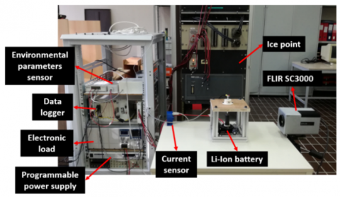
The cell charge and discharge process are managed by a programmable power supply (RMX-4125) and DC electronic load (RMX-4005) by National Instruments, controlled trough a LabVIEW routine. The battery current and voltage was constantly measured during all the process. Voltage is directly measured with NI 6289 data acquisition device with a resolution of 0.076 mV and an uncertainty of ±0.25 mV. The operating current is measured with a LEM current transducer IT65-S with an uncertainty of ±0.02 A. For all the experimental tests also ambient parameters (temperature and relative humidity) are acquired with an Omega transmitter HX93B series with an uncertainty of ±0.6°C and ±2.5% respectively for temperature and humidity measurements.
Battery surface temperature measurement was performed both with thermocouples and IR thermography. Four type T thermocouple was placed along the battery height with a high thermal conductivity adhesive. The thermocouples are attached to an ice point reference (Kaye Instruments) before being acquired by the data logger (NI SCXI-1303). Thermographic measurements are performed with a FLIR SC3000 IR camera equipped with a 320 x 240 QWIP sensor array and a 20° lens. The thermal sensitivity is 20 mK at 30°C with an uncertainty of ±1 % of the measured value. The battery was covered with a black matte paint of emissivity 0.94, measured trough a black body. Figure 1 shows the measurement set-up above described.
Figure 1. Experimental set-up
Eq. (1) requires several parameters to be found in order to evaluate battery heat generation. In this paper three kind of tests are performed to experimentally measure these quantities. UOC was evaluated through cycles of discharge and relaxation. EHC with a potentiometric test. Finally, a constant current discharge was applied to the battery in order to measure the battery voltage, operating current and surface temperature.
4.1 Open circuit potential
The open circuit potential was evaluated every 10 % of SOC through the following method. First the battery was discharged at the specific SOC. Then it was allowed to relax for 1 hour. At the end of relaxation, the voltage value reached by the battery is the UOC at the specific SOC (Figure 2).
Figure 2. Open circuit potential of the battery
4.2 Entropic heat coefficient
The most common method to measure the entropic heat coefficient is potentiometric test [17, 18, 20, 22]. Thomas at al., [22], underlines that is more suitable to vary the temperature at a specific SOC. Nieto at al. [17], state that the entropic heat coefficient is not affected by temperature chosen for the thermal cycle and if the battery was on charge or discharge.
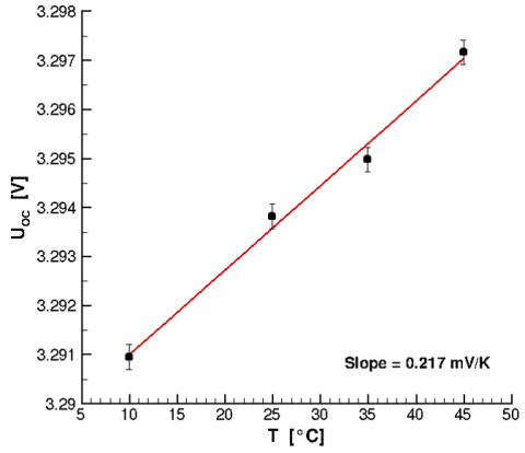
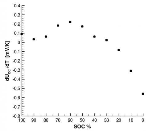
The battery was discharged to a specific SOC and allowed to relax. The relaxation was followed by a thermal cycle in a thermostatic bath while measuring the open circuit potential The thermal cycle used in this paper is made up of 3 h at 25°C, 3 h at 10°C, 3 h at 35°C, 3 h at 45°C and 3 h at 25°C. This procedure was repeated every 10 % of SOC until complete discharge. Figure 3 shows an example of the open circuit potential variation during the thermal cycle. The mean of voltage measured at each temperature step was plotted as a function of temperature as show in Figure 4. The gradient of the curve determines the entropic coefficient at each SOC. In this case, the overall uncertainty in the UOC is ±0.25 mV and ±0.001 mV/K for the EHC. Finally, Figure 5 shows the EHC measured as a function of SOC. The EHC assume positive values until an SOC of 30%; after that it becomes negative. Similar behaviour was also observed in literature [20, 23].
Figure 3. Open circuit potential measured during thermal cycle at SOC 50%
Figure 4. UOC as a function of temperature at SOC 50%
Figure 5. Entropic heat coefficient as a function of SOC
Table 1. Constant current discharge tests
|
C-rate |
Discharge current [A] |
Discharge time [s] |
|
0.5Table size |
1.25can be |
7200edited |
|
1 |
2.5 |
3600 |
|
2 |
5 |
1800 |
|
3 |
7.5 |
1200 |
|
4 |
10 |
900 |
|
5 |
12.5 |
720 |
|
10 |
25 |
360 |
4.3 Constant current discharge
In this test the battery is fully discharged with a constant current. The discharge was stopped when the cell potential reaches the minimum voltage of 2 V. The test was performed at ambient temperature (between 21°C and 23°C) and under a wide range of C-rate (Table 1). After the complete discharge, the battery was allowed to rest for half an hour and then fully charged.
During discharge the battery voltage, operating current and temperature measured by thermocouples are continuously recorded at 10 Hz, while IR images are taken once per second. Each image acquired during discharge was then subtracted with a reference thermal image taken before the test starts. All temperature measurements are referred to battery initial value so to avoid the influence of ambient temperature variation.
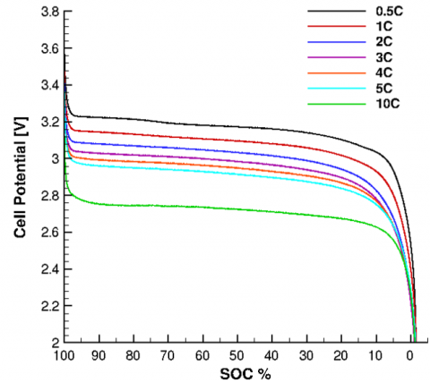
Cell potential at different discharge rates is reported as a function of SOC in Figure 6. When a current is required from the battery the cell potential have a first sudden fall due to its internal resistance, then it flattens until a very low SOC when the voltage falls down to its minimum value. For higher discharge current, voltage value of the flatten zone always decreases and the difference with the open circuit potential rapidly increases.
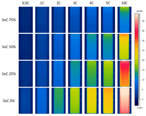
During discharge, the battery surface temperature increases especially at low SOC. The temperature rise is due to the loss of initial energy as heat generated by the battery. Figure 7 shows the thermal images acquired. Four SOC levels have been chosen as representative points for the discharge. Thermal images underline the battery warm up during discharge. It is immediately clear that higher current produces a higher temperature rise.
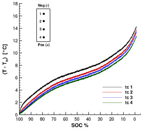
The temperature reached by the battery at the end of discharge is quite moderate for low C-rate (about 10°C higher of ambient temperature) but becomes very high when higher C-rate occurs. In these cases, the battery far exceeds its temperature operating range. Indeed, for a discharge current of 10C the final temperature was 45°C higher than initial value. Furthermore, for all C-rate the battery surface temperature is not uniform across its height but there is a higher temperature in the upper zone at the negative electrode. This trend is also confirmed by thermocouples measurements (Figure 8).
Figure 6. Cell potential for different C-rates
Figure 7. Thermal images of the battery at various C-rates and SOC levels
Figure 8. Temperature measured by the four thermocouples for a 2C discharge current
Once the open circuit potential and the entropic heat coefficient were measured, the thermal power generated can be found with Eq. (1) for all the constant current discharges. We obtain a measurements uncertainty lesser than ±2 % for all the parameters involved.
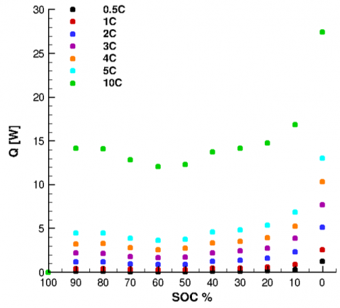
Figure 9. Thermal power generated at various C-rate
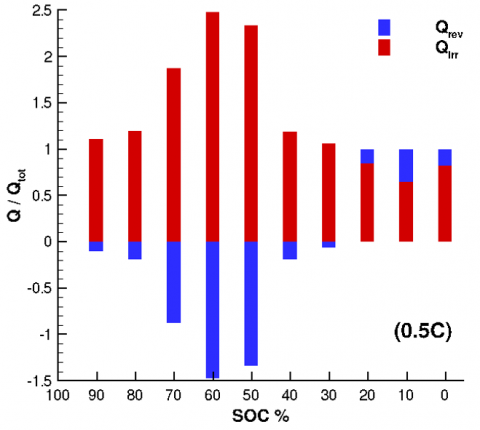
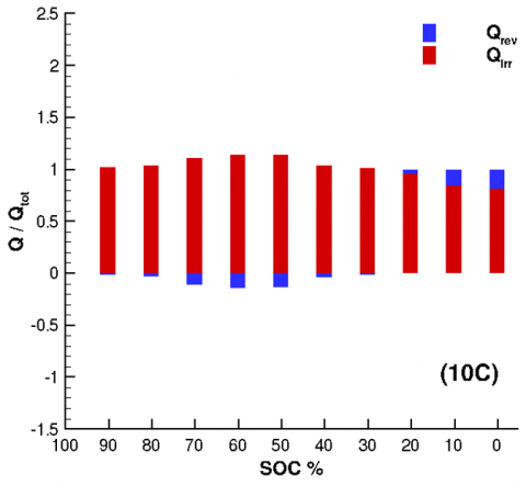
Figure 10. Irreversible and reversible heat contribution to the total thermal power for different discharge current
Figures 9 shows the instantaneous thermal power at each SOC. Since the overpotential grows with the discharge current, also the thermal power is greater for higher C-rate. Furthermore, thermal power has a faster increase at low SOC where the battery voltage has an abrupt decay and the entropic heat coefficient becomes negative. In these zones the reversible component is positive, and it increases the total thermal power generated. Otherwise, when EHC reaches its maximum positive value (at an SOC of 60%) thermal power has a minimum for all discharge currents. Already from these considerations can be seen how the thermal power generated by the battery is strongly affected by the reversible part.
The two contributions of the total thermal power generated were individually evaluated. Figure 10 shows the ratio between the reversible and the irreversible heat with the total thermal power as a function of SOC at C-rate 0.5C and 10C. The reversible heat considerably affects the total heat generated by the battery especially at low C-rate where it has the same order of magnitude of the irreversible heat. Where the EHC is positive the reversible heat is negative and the discharge process is endothermic. In this case the reversible part is subtracted to the total heat generation. Otherwise, from an SOC of 20% the EHC becomes negative, the discharge process is exothermic and the reversible component increases the total thermal power generation. From Figure 10 is clearly evident that the irreversible part of heat generation must be considered for the evaluation of the battery heat generation especially at low C-rates. However, with higher discharge rates reversible contribution is always less significant. Indeed, at higher C-rate, the overpotential is very large and the irreversible term of Eq. (1) becomes predominant.
In this paper thermal behaviour of a LiFePO4 Lithium battery under various discharge current was experimentally investigated. Heat generation was evaluated with a simplified thermal model both considering irreversible and reversible contributions. Surface temperature was measured both with thermocouples and infrared thermography. Experimental results were used to evaluate battery thermal power with a heat generation simplified model.
The results show an increase of thermal power when the battery is subjected to higher discharge currents. This is due to the increase of the overpotential since the battery shows a higher voltage drop if compared with the open circuit potential. For all the discharge currents tested the greatest thermal power was observed when low SOC occurs due to the abrupt decay of voltage. This leads also to a sharp increase of temperature when SOC go down 20%.
The contributions of reversible and irreversible heat to the total thermal power were carefully evaluated. The results show that the reversible part can not be assumed constant or not considered at all since it strongly affects the total thermal power and temperature trend especially at low C-rate.
Infrared thermography and thermocouples measurements show that surface temperature is not uniform along the height of the battery. Indeed, there is a greater warm up in the upper zone, corresponding to the negative electrode. Furthermore, the battery surface temperature reaches very high values, far over the maximum allowed temperature. In this case a proper designed BTMS is crucial for an efficient and safety functioning of the battery. The correct determination of the battery heat generation allows to improve the BTMS design method.
[1] Masayoshi, W.A.D.A. (2009). Research and development of electric vehicles for clean transportation. Journal of Environmental Sciences, 21(6): 745-749. https://doi.org/10.1016/s1001-0742(08)62335-9
[2] De Wilde, H.P.J., Kroon, P. (2013). Policy options to reduce passenger cars CO2 emissions after 2020. Energy Research Centre of the Netherlands.
[3] Lowe, M., Tokuoka, S., Trigg, T., Gereffi, G. (2010). Lithium-ion batteries for electric vehicles. The US Value Chain, Contributing CGGC researcher: Ansam Abayechi.
[4] Karden, E., Ploumen, S., Fricke, B., Miller, T., Snyder, K. (2007). Energy storage devices for future hybrid electric vehicles. Journal of Power Sources, 168(1): 2-11. https://doi.org/10.1016/j.jpowsour.2006.10.090
[5] Pesaran, A., Santhanagopalan, S., Kim, G.H. (2013). Addressing the impact of temperature extremes on large format li-ion batteries for vehicle applications (presentation) (No. NREL/PR-5400-58145). National Renewable Energy Lab. (NREL), Golden, CO (United States).
[6] Park, H. (2013). A design of air flow configuration for cooling lithium ion battery in hybrid electric vehicles. Journal of Power Sources, 239: 30-36. https://doi.org/10.1016/j.jpowsour.2013.03.102
[7] Mohammadian, S.K., Zhang, Y. (2015). Thermal management optimization of an air-cooled Li-ion battery module using pin-fin heat sinks for hybrid electric vehicles. Journal of Power Sources, 273: 431-439. https://doi.org/10.1016/j.jpowsour.2014.09.110
[8] Saw, L.H., Tay, A.A.O., Zhang, L.W. (2015). Thermal management of lithium-ion battery pack with liquid cooling. In 2015 31st Thermal Measurement, Modeling & Management Symposium (SEMI-THERM), pp. 298-302. https://doi.org/10.1109/SEMI-THERM.2015.7100176
[9] Fang, Y., Ye, F., Zhu, Y., Li, K., Shen, J., Su, L. (2020). Experimental investigation on system performances and transient response of a pumped two-phase battery cooling system using R1233zd. Energy Reports, 6: 238-247. https://doi.org/10.1016/j.egyr.2020.07.025
[10] Duan, X., Naterer, G.F. (2010). Heat transfer in phase change materials for thermal management of electric vehicle battery modules. International Journal of Heat and Mass Transfer, 53(23-24): 5176-5182. https://doi.org/10.1016/j.ijheatmasstransfer.2010.07.044
[11] Gan, Y., He, L., Liang, J., Tan, M., Xiong, T., Li, Y. (2020). A numerical study on the performance of a thermal management system for a battery pack with cylindrical cells based on heat pipes. Applied Thermal Engineering, 179: 115740. https://doi.org/10.1016/j.applthermaleng.2020.115740
[12] Chen, M., Li, J. (2020). Nanofluid-based pulsating heat pipe for thermal management of lithium-ion batteries for electric vehicles. Journal of Energy Storage, 32: 101715. https://doi.org/10.1016/j.est.2020.101715
[13] Smith, K., Wang, C.Y. (2006). Power and thermal characterization of a lithium-ion battery pack for hybrid-electric vehicles. Journal of Power Sources, 160(1): 662-673. https://doi.org/10.1016/j.jpowsour.2006.01.038
[14] Pals, C.R., Newman, J. (1995). Thermal modeling of the lithium/polymer battery: I. Discharge behavior of a single cell. Journal of the Electrochemical Society, 142(10): 3274. https://doi.org/10.1149/1.2049974
[15] Chen, Y., Evans, J.W. (1993). Heat transfer phenomena in lithium/polymer‐electrolyte batteries for electric vehicle application. Journal of the Electrochemical Society, 140(7): 1833. https://doi.org/10.1149/1.2220724
[16] Chen, S.C., Wang, Y.Y., Wan, C.C. (2006). Thermal analysis of spirally wound lithium batteries. Journal of the Electrochemical Society, 153(4): A637. https://doi.org/10.1149/1.2168051
[17] Nieto, N., Díaz, L., Gastelurrutia, J., Alava, I., Blanco, F., Ramos, J.C., Rivas, A. (2012). Thermal modeling of large format lithium-ion cells. Journal of the Electrochemical Society, 160(2): A212. https://doi.org/10.1149/2.042302jes
[18] Manikandan, B., Yap, C., Balaya, P. (2017). Towards understanding heat generation characteristics of Li-Ion batteries by calorimetry, impedance, and potentiometry studies. Journal of The Electrochemical Society, 164(12): A2794. https://doi.org/10.1149/2.1811712jes
[19] Rad, M.S., Danilov, D.L., Baghalha, M., Kazemeini, M., Notten, P.H.L. (2013). Adaptive thermal modeling of Li-ion batteries. Electrochimica Acta, 102: 183-195. https://doi.org/10.1016/j.electacta.2013.03.167
[20] Forgez, C., Do, D. V., Friedrich, G., Morcrette, M., Delacourt, C. (2010). Thermal modeling of a cylindrical LiFePO4/graphite lithium-ion battery. Journal of Power Sources, 195(9): 2961-2968. https://doi.org/10.1016/j.jpowsour.2009.10.105
[21] Bernardi, D., Pawlikowski, E., Newman, J. (1985). A general energy balance for battery systems. Journal of the electrochemical society, 132(1): 5. https://doi.org/10.1149/1.2113792
[22] Thomas, K.E., Bogatu, C., Newman, J. (2001). Measurement of the entropy of reaction as a function of state of charge in doped and undoped lithium manganese oxide. Journal of the Electrochemical Society, 148(6): A570. https://doi.org/10.1149/1.1369365
[23] Geifes, F., Bolsinger, C., Mielcarek, P., Birke, K.P. (2019). Determination of the entropic heat coefficient in a simple electro-thermal lithium-ion cell model with pulse relaxation measurements and least squares algorithm. Journal of Power Sources, 419: 148-154. https://doi.org/10.1016/j.jpowsour.2019.02.072