Bernardo Buonomo | Anna di Pasqua | Oronzio Manca* | Sergio Nappo
OPEN ACCESS
Heat exchangers, widely used in the industrial sector, are often the subject of study to find techniques to increase their efficiency. One of the most effective techniques is that which involves the use of metal foams. The application of metal foams in heat exchangers allows for greater efficiency, a more compact and lighter device, high thermal conductivity and a large accessible surface per unit of volume.
Entropy generation analysis on compact heat exchanger in aluminum foam is accomplished. The governing equations in two-dimensional steady state regime are written in local thermal non-equilibrium (LTNE). The geometrical domain under investigation is made up of a plate in aluminum foam with inside a single array of five circular tubes. The foams are characterized by a porosity in the range from 0.90 to 0.97 and different pores per inch, equal to 5, 10, 20 and 40. The LTNE assumption is employed to simulate the heat transfer between metal foam and air and evaluate the global entropy generations. The compact heat exchanger at different air flow rates is studied with an assigned surface tube temperature. The results in terms of global entropy generations and in terms of Bejan number Be related to the thermal and viscous effects are given.
aluminum foam, heat exchanger, heat transfer enhancement, entropy generation method
Nowadays it is increasingly important to look for new techniques that can lead to an improvement in the efficiency of the various industrial plants trying to reduce the environmental impact. Several authors [1-3] find in the metal foams, assumed as porous media, a tempting method for heat transfer enhancement. In fact, these materials are widely employed in many industrial applications such as heat exchangers [4], fuel cells and solar power systems [5], automotive thermoelectric generator [6], latent thermal energy storage [7]. The heat exchanger is one of the most employed industrial components. A good solution is the application of open-cell metal foams as replacement for the conventional fins in order to enhance the efficiency of the system, as demonstrated in many examples [8-11].
Entropy minimization in heat exchangers considered by Bejan [12-14]. Entropy generation minimization analysis is important for system optimizations especially for heat exchangers, where pumping power and rate of heat transfer should be optimized for the best performance of the system.
Rashidi et al. [15] carried out a review on the entropy generation method applied on different solar thermal systems including solar collectors and solar heat exchangers. The authors studied also the effect of passive such as nanofluids and porous materials. The main result obtained by this review is that the local approaches for estimating the entropy generation in solar systems represent the opportunity to study the design changes on the system efficiency more accurately.
A study on the optimal position of porous medium for a double-pipe heat exchanger using the entropy generation method was accomplished by Akbarzadeh et al. [16]. The first and second laws of thermodynamics are employed to evaluate the best configuration of the porous inserts to obtain maximum heat transfer and minimum pressure drop and entropy generation inside the system. The results show that for outer tube presents a larger pressure drop when the porous layer is in the inner wall. Furthermore, for inner tube, the best position of porous insert is at the center.
Torabi et al. [17] accomplished a numerical investigation on entropy generation in turbulent forced convection in porous media by the use of RANS models. Circular, longitudinal elliptical and transverse elliptical cross-sectional configurations were analyzed. The results showed that the longitudinal elliptical cross-sectional configuration presents a higher heat transfer respect to the circular and transverse elliptical cross-sectional configurations. Furthermore, the longitudinal elliptical cross-sectional configuration is characterized by the lowest entropy generation.
Alvandifar et al. [18] executed a numerical investigation on the staggered and inline tube bundles with three rows covered by a porous layer by first and second law of thermodynamics. The results demonstrate that the configuration with bundles with porous layer wrapped flat tubes has a higher thermal performance and lower entropy generation rate respect to those of porous layer wrapped circular tubes, especially for the staggered configuration.
A numerical study on the performance of an annular heat exchanger with a porous insert for a turbulent flow with the use of the entropy generation method was accomplished by Chikh and Allouache [19]. The data show that, for high values of temperature difference, most of irreversibilities are due to heat transfer, whereas, for low values of temperature difference, the irreversibility due to fluid friction are major mainly for higher porous layer thicknesses and for low values of permeability.
A numerical investigation on entropy generation on forced convection through porous media using pore scale modeling was executed by Torabi et al. [20]. The configurations under analysis were circular and square cross-sectional configurations. The local entropy generation rate increases in the inlet region when the Reynolds number increases. Furthermore, the entropy is higher in the inlet of the domain for low value of Reynolds number; instead, the entropy generation rate is higher on the cylinders’ walls for higher Reynolds number.
Li et al. [21] executed a numerical analysis on a high performance model Stirling engine with compact porous-sheets heat exchangers. The authors develop an optimization method in order to evaluate the entropy generation due to the flow friction and irreversible heat transfer. The results show that the regular shaped microchannels allow you to obtain a relatively high power and a thermal efficiency of 43.9%, for their extremely small flow friction loss and good heat transfer behavior.
A numerical analysis on optimization of peripheral finned-tube evaporators with the application of entropy generation minimization was carried out by Pussoli et al. [22]. The authors found that there is an optimum NTU associated with a minimum entropy generation number.
The present numerical analysis is an application of the entropy generation method (EGM) used for the evaluation of the thermal and fluid-dynamic behavior of a compact heat exchanger made up of aluminum foams characterized by distinct porosity values. The results in terms of global entropy generations and Be (Bejan number) related to the thermal and viscous effects are given.
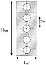
A metal foam heat exchanger in forced convection steady laminar flow represents the physical domain. The 2D sketch of the compact heat exchange system under investigation is presented in Figure1. An array of five tubes enclosed inside the porous medium constituted the tubular heat exchanger. The distance between center-to-center of two consecutive tubes, indicated as 2H, is 38 mm and the diameter d of the tubes is 12 mm. The system is characterized by the height Htot of 190 mm and the length Lmf of 38 mm.
Figure 1. Physical domain
The local volume averaging process is applied at the microscopic flow equations as written in [23] in order to replicate the thermal and fluid dynamic behaviors inside the domain. Whitaker wrote the governing equations from the Navier-Stokes and energy equation [24].
The Darcy–Forchheimer-Brinkman model and LTNE condition are consider to describe the presence of metal foam.
The variables of the equations are evaluated estimating the average of the local variables over an appropriate volume, called Representative Elementary Volume (REV), applied the local volume averaging technique. The metal foam is assumed homogeneous and isotropic and the thermal and physical properties of the fluid and solid phases are considered constant. In addition, the viscous dissipation, buoyancy force, and the thermal contact resistances between the tube surface and foam are overlooked. Applying the hypothesis above indicated, the governing equations are the following:
-Continuity equation
$\frac{\partial u}{\partial x}+\frac{\partial v}{\partial y}=0$ (1)
-x- momentum equation
$\rho_{f}\left(\frac{u}{\varepsilon^{2}} \frac{\partial u}{\partial x}+\frac{v}{\varepsilon^{2}} \frac{\partial u}{\partial y}\right)=-\frac{\partial p}{\partial x}+\frac{\mu_{f}}{\varepsilon}\left(\frac{\partial^{2} u}{\partial x^{2}}+\frac{\partial^{2} u}{\partial y^{2}}\right)+$$-\frac{\mu_{f}}{K} u-\frac{C_{F}}{K^{1 / 2}} \rho_{f} \sqrt{u^{2}+v^{2}} u$ (2)
-y-momentum equation
$\rho_{f}\left(\frac{u}{\varepsilon^{2}} \frac{\partial v}{\partial x}+\frac{v}{\varepsilon^{2}} \frac{\partial v}{\partial y}\right)=-\frac{\partial p}{\partial y}+\frac{\mu_{f}}{\varepsilon}\left(\frac{\partial^{2} v}{\partial x^{2}}+\frac{\partial^{2} v}{\partial y^{2}}\right)+$$-\frac{\mu_{f}}{K} v-\frac{C_{F}}{K^{1 / 2}} \rho_{f} \sqrt{u^{2}+v^{2}} v$ (3)
where, ɛ is the porosity, ρf and μf are fluid density and viscosity, u and v are correspondingly the velocity components in Cartesian coordinates, K and CF are respectively the permeability and the inertial coefficient of metal foam.
-Fluid phase energy equation
$\left(\rho_{f} c_{p}\right)_{f}\left(u \frac{\partial T_{f}}{\partial x}+v \frac{\partial T_{f}}{\partial y}\right)=\varepsilon k_{f}\left(\frac{\partial^{2} T_{f}}{\partial x^{2}}+\frac{\partial^{2} T_{f}}{\partial y^{2}}\right)$$+h_{s f} \alpha_{s f}\left(T_{s}-T_{f}\right)$ (4)
-Solid phase energy equation
$(1-\varepsilon) k_{s}\left(\frac{\partial^{2} T_{s}}{\partial x^{2}}+\frac{\partial^{2} T_{s}}{\partial y^{2}}\right)-h_{s f} \alpha_{s f}\left(T_{s}-T_{f}\right)=0$ (5)
where, cp is the specific heat, kf and ks are the fluid phase and solid matrix thermal conductivity, Tf and Ts are the temperature of fluid and solid phase of metal foam, respectively. In the last term in both energy equations, αsf and hsf are respectively the specific surface area density and the interfacial heat transfer coefficient between the fluid and solid matrix, due to the LTNE hypothesis.
The equations for the evaluation of the entropy generation for local thermal non-equilibrium porous model are the following [25]:
-Fluid phase entropy generation
$\dot{S}_{g e n, f}^{\prime \prime \prime}=\underbrace{\frac{\varepsilon k_{f}}{T_{f}^{2}}\left[\left(\frac{\partial T_{f}}{\partial x}\right)^{2}+\left(\frac{\partial T_{f}}{\partial y}\right)^{2}\right]+\frac{\alpha_{s f} h_{s f}\left(T_{s}-T_{f}\right)^{2}}{T_{s} T_{f}}}_{\dot{s}_{g e n, \Delta T}^{'''}}$$+\underbrace{\frac{\mu_{f}}{T_{f}} \Phi+\frac{\mu_{f} \varepsilon}{K T_{f}}\left(u^{2}+v^{2}\right)+\frac{C_{F} \rho \varepsilon^{2}}{T_{f} \sqrt{K}}\left(u^{2}+v^{2}\right)^{3 / 2}}_{\dot{s}_{g e n, \Delta p}^{'''}}$ (6)
where, Φ in Eq. (6) is the well-known dissipation function; its form for incompressible fluid at a two-dimensional rectangular coordinate is:
$\Phi=2\left[\left(\frac{\partial u}{\partial x}\right)^{2}+\left(\frac{\partial v}{\partial y}\right)^{2}\right]+\left(\frac{\partial u}{\partial y}+\frac{\partial v}{\partial x}\right)^{2}$ (7)
The fourth term on the right-hand side of Eq. (6) considers the irreversibility rate of internal energy per unit volume by viscous drag in the porous section, and the last term in Eq. (6) represents the irreversibility rate of internal energy per unit volume by form drag in the porous section.
-Solid phase entropy generation
$\dot{S}_{g e n, s}^{\prime \prime \prime}=\underbrace{\frac{(1-\varepsilon) k_{s}}{T_{s}^{2}}\left[\left(\frac{\partial T_{s}}{\partial x}\right)^{2}+\left(\frac{\partial T_{s}}{\partial y}\right)^{2}\right]+\frac{\alpha_{s f} h_{s f}\left(T_{f}-T_{s}\right)^{2}}{T_{s} T_{f}}}_{s_{g e n, \Delta T}^{'''}}$ (8)
The correlations of Calmidi are used to evaluate K and CF [26]:
$K=0.00073(1-\varepsilon)^{0.0224}\left(\frac{d_{f}}{d_{p}}\right)^{-1.11} d_{p}^{2}$ (9)
and
$C_{F}=0.00212(1-\varepsilon)^{-0.132}\left(\frac{d_{f}}{d_{p}}\right)^{-1.63}$ (10)
where, df and dp are respectively the fiber and pore diameter of the aluminum foam. These parameters are in relation with the nature of the metal foam by means of the following relationships [27]:
$\frac{d_{f}}{d_{p}}=1.18 \sqrt{\frac{1-\varepsilon}{3 \pi}}\left(\frac{1}{1-e^{-(1-\varepsilon) / 0.04}}\right)$ (11)
and
$d_{p}=\frac{0.0224}{\omega}$ (12)
w is the pores density of the metal foam, i.e., the number of pores across one inch (PPI). The following correlations are adopted to estimate asf and hsf [28]:
$\alpha_{s f}=\frac{3 \pi d_{f}}{\left(0.59 d_{p}\right)^{2}}\left(1-e^{-(1-\varepsilon) / 0.04}\right)$ (13)
and
$h_{s f}=\left\{\begin{array}{c}\left(0.75 R e_{d_{f}}^{0.4} P r_{a i r}^{0.37}\right)\left(\frac{k_{f}}{d_{f}}\right), 1 \leq R e_{d f} \leq 40 \\ \left(0.51 R e_{d_{f}}^{0.5} P r_{a i r}^{0.37}\right)\left(\frac{k_{f}}{d_{f}}\right), 40 \leq R e_{d f} \leq 10^{3} \\ \left(0.26 R e_{d_{f}}^{0.6} P r_{a i r}^{0.37}\right)\left(\frac{k_{f}}{d_{f}}\right), 10^{3} \leq R e_{d f} \leq 2 \times 10^{5}\end{array}\right.$ (14)
where, Redf is the local Reynolds number referred to ligament diameter:
$R e_{d_{f}}=\frac{\rho_{f} u_{0} d_{f}}{\mu_{f}}$ (15)
Prair is the air Prandtl number that is evaluated as:
$P r_{a i r}=\frac{\mu_{f} c_{p}}{k_{f}}$ (16)
The parameters of the metal foams, for different porosity and PPI, are listed in Table 1.
Table 1. Parameters of the aluminum metal foams
|
PPI |
ɛ |
K(m2) |
CF |
|
5 |
0.90 |
2.3148x10⁻⁷ |
0.0775 |
|
5 |
0.94 |
2.8636x10⁻⁷ |
0.0920 |
|
5 |
0.978 |
3.1868x10⁻⁷ |
0.0958 |
|
10 |
0.90 |
5.7871x10⁻⁸ |
0.0775 |
|
10 |
0.934 |
6.9426x10⁻⁸ |
0.0934 |
|
10 |
0.9724 |
8.0097x10⁻⁸ |
0.0967 |
|
20 |
0.90 |
1.4468x10⁻⁸ |
0.0775 |
|
20 |
0.9365 |
1.7582x10⁻⁸ |
0.0944 |
|
20 |
0.9748 |
2.0015x10⁻⁸ |
0.0952 |
|
40 |
0.91 |
3.8158x10⁻⁹ |
0.0822 |
|
40 |
0.9361 |
4.3866x10⁻⁹ |
0.0943 |
|
40 |
0.972 |
5.0053x10⁻⁹ |
0.0972 |
The finite volume method is applied in order to resolve the governing equations. Fluent 18.2 is used to carried out the numerical investigations. The SIMPLE algorithm is applied for the pressure-velocity coupling; the gradient evaluation for the spatial discretization is based on least square cell. The PRESTO algorithm is executed for the pressure calculation and the second order upwind scheme is used for energy and momentum equations. Convergence criteria are considered equal to 10-5 for the continuity and the velocity components; while for the energy equal to 10-8. The numerical domain is represented in the Figure 2. It is made up of half tube totally enclosed by the metal foam. The radius of the tube is equal to d/2, indicated as r equal to 6 mm. The height of system is equal to H and the length Lmf is the same of the physical domain. The heat exchanger is placed in a channel with a rectangular cross section of 19 mm with L1 and L2 equal to 200 mm and 800 mm, respectively.
Figure 2. Computational domain
The grid is made up of rectangular cells in the air channel and around the tube and triangular cells in the region of metal. Three different types of grids were investigated to find an independent solution from the mesh. They are constituted by 5786 cells, 23272 cells and 92702 cells, respectively. In corresponding of an inlet air velocity equal 0.12 m/s and of a metal foam with porosity 0.9365 and 20 PPI, the evaluation of average $\overline{h_{\text {tot }}}$ on the tube surface, as showed in Table 2, points out that the grid with 4018 cells had 0.08% error than the mesh with 64351 cells. The grid adopted for the computational was the one with 4018 elements because with it a compromise between solution accuracy and convergence time was obtained.
Table 2. Grid independence and numerical results
|
Cells Number |
$\overline{h_{\text {tot }}}$ (W/m2K) |
% error |
|
5786 |
146.63 |
0.08% |
|
23272 |
146.54 |
0.02% |
|
92702 |
146.51 |
------- |
In this analysis, the Reynolds number Red, calculated as:
$R e_{d}=\frac{\rho_{f} u_{0} d}{\mu_{f}}$ (17)
ranges from 100 to 1000. The inlet air velocities u0 are evaluated from the definition of Red and the following values are obtained, as shown in Table 3.
Table 3. Inlet air velocity values
|
Red |
uo (m/s) |
|
100 |
0.12 |
|
300 |
0.37 |
|
500 |
0.61 |
|
700 |
0.85 |
|
800 |
0.97 |
|
1000 |
1.22 |
The boundary conditions of the problem are the following: the upper and bottom edges are symmetric, the tube wall is an isothermal edge with the temperature value equal to 323.16 K and indicated as Tw, the inlet air velocity u0 assumes the values above indicated in the Table 3, the inlet air temperature, indicated as T0, is equal to 288.16 K and to the exit is imposed the overflow condition. The reference length is the diameter of the tube d for the dimensionless number.
The entropy generation method analyses are accomplished for different inlet air velocities and for a fixed temperature on the external surface of tube equal to 323.16 K. The air flow is laminar and the LTNE model is considered to write the energy equations. The total global entropy generation $\dot{S}_{g e n, t o t}$ is evaluated as:
$\dot{S}_{g e n, t o t}=\dot{S}_{g e n, f}+\dot{S}_{g e n, s}$ (18)
where, $\dot{S}_{g e n, f}$ and $\dot{S}_{g e n, s}$ are the fluid phase and solid matrix global entropy generation, respectively. The global total entropy generation results, evaluated in the porous section, for different porosity values are plotted, in the Figure 3 only for 5 PPI and 40 PPI because the behavior of the $\dot{S}_{g e n, t o t}$ is the same for 10 PPI and 20 PPI values, respectively.
Figure 3. Global entropy generation as a function of inlet velocity for different porosity and: (a) 5 PPI, (b) 40 PPI
The $\dot{S}_{\text {gen,tot }}$ increases with increasing inlet velocity values for all PPI. Furthermore, it is possible to see, in the Figure 3.a, that, for velocity values minor than 0.85 m/s, the global entropy generation increases with the increase of porosity; while, for higher velocity values, the lower $\dot{S}_{\text {gen,tot }}$ is obtained in corresponding to the porosity equal to 0.978. The same trend is also achieved for 20 PPI. In addition, from the Figure 3.b, one can notice the same behavior of the global entropy generation, but with the difference that there is a decrease of $\dot{S}_{\text {gen,tot }}$ at the highest porosity for a greater velocity value, near to 0.97 m/s. Among the various metal foam samples analyzed, the one showing the same trend of 40 PPI is the foam characterized by a pore density equal to 10.
In the Figure 4, the total global entropy generation, calculated in the porous medium, is presented for several PPI values approximately to the same porosity around 0.90 and 0.97, respectively.
Figure 4. Global entropy generation as a function of inlet velocity for different PPI values and: (a) ε≅0.90, (b) ε≅0.97
It is possible to see that, both in the Figure 4.a and in Figure 4.b, the total global entropy generation increases with increasing PPI values. This behavior is because as the number of pores per inch increases, there is an increment in the pressure drop, which consequently leads to an increase in the entropic generation component linked to friction.
In the Figure 5, the Bejan number Be evaluated in the metal foam region are showed as a function of Reynolds number. Bejan number Be, a typical parameter employed in the entropy generation method, is defined as:
$B e=\frac{\dot{S}_{g e n, \Delta T}}{\dot{S}_{g e n, \Delta T}+\dot{S}_{g e n, \Delta p}}$ (19)
where, in the denominator the first term indicates the entropy generation due to the heat transfer between finite temperature difference $\dot{S}_{g e n, \Delta T}$ and the second term indicates the entropy generation by the pressure drop due to friction $\dot{S}_{g e n, \Delta p}$. The sum of two terms of denominator of Eq. (19) represents the total global entropy generation. The Bejan number is showed in Figure 5, for 10 PPI and 20 PPI.
Figure 5. Bejan number as a function of Reynolds number for different porosity and: (a) 10 PPI, (b) 20 PPI
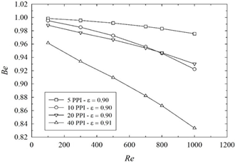
The Bejan number Be decreases with increasing inlet velocity values for all numbers of pores per inch, because of the increment of the term $\dot{S}_{g e n, \Delta p}$. Moreover, it is possible to see, in the Figure 5.a, that, for Reynolds number minor than 800, the Bejan number increases with the increase of porosity; while, for higher Re values, the lower Be is achieved in corresponding to the porosity equal to 0.9724. The same trend is also obtained for 40 PPI. In addition, from the Figure 5.b, it is possible to notice it is possible to note once again the increase in the Bejan number as the porosity increases, but in this case a lower Bejan number is recorded for the higher porosity at a lower Reynolds number value than before ($R e \cong 600$). The metal foam that has the same Reynolds value for which the Bejan number decreases with increasing porosity is the one characterized by a number of pores per inch equal to 5. In the Figure 6, the Bejan number Be is illustrated at varying Reynolds number and for several PPI values at roughly the same porosity around 0.90 and 0.97, respectively. One can observe that, in the Figure 6.a, the Bejan number decreases with increasing PPI values except for 10 PPI and 20 PPI for a Re value greater than 800. In the Figure 6.b and 6.c, however, Be increases as the number of pores per inch decreases for any Reynolds value. The lowest Be value, at which the generation due to friction weighs more, is recorded for 40 PPI and porosity equal to 0.91 and is approximately equal to 0.83.
(a)
(b)
(c)
Figure 6. Bejan number as a function of Re for different PPI values and: (a) $\varepsilon \cong 0.90$, (b) $\varepsilon \cong 0.94$, (c) $\varepsilon \cong 0.97$
A numerical investigation on a heat exchanger with aluminum foams characterized by different porosity, from 0.90 to about 0.97, has been accomplished to evaluate the global entropy generation of the system. The results in terms of entropy generation show that the foams with higher porosity values increases the in corresponding to lower velocity values. Furthermore, the different results in terms of entropy generation are also presented as the number of PPI varies by fixing the porosity demonstrating that the increases with increasing numbers of pores per inch. The results are also showed in terms of Bejan number. Be increases with the increase of porosity; while, for higher Re values, the lower Be is achieved in corresponding to the porosity approximately equal to 0.97. In addition, when the porosity is fixed and PPI number changes, Bejan number increases as the number of pores per inch decreases.
This research was partially funded by MIUR (Ministero dell’Istruzione, dell’Università e della Ricerca), grant number PRIN-2017F7KZWS and by Università degli Studi della Campania “Luigi Vanvitelli” with the grant number D.R. n. 138 under NanoTES project - V:ALERE program 2020.
|
A |
cross section, m2 |
|
Be |
Bejan number |
|
CF |
drag factor coefficient |
|
cp |
specific heat, J kg-1 K-1 |
|
d |
tube diameter, m |
|
df dp |
fiber diameter, m pore diameter, m |
|
hsf |
interfacial heat transfer coefficient, W m-2 K-1 |
|
H |
half pitch, m |
|
Htot |
heat exchanger height, m |
|
k |
thermal conductivity, W m-1 K-1 |
|
K |
porous permeability, m2 |
|
L |
thickness of porous media, m |
|
p |
static pressure, Pa |
|
Pr |
Prandtl number |
|
r |
radius tube, m |
|
Re |
Reynolds number |
|
s |
curvilinear abscissa, m |
|
$\dot{S}_{\text {gen }}$ |
global entropy generation, W K-1 |
|
T |
Temperature, K |
|
u |
x-velocity, m s-1 |
|
u0 |
inlet air velocity, m s-1 |
|
v |
y-velocity, m s-1 |
|
v |
velocity vector, m s-1 |
|
x |
Cartesian axis direction, m |
|
y |
Cartesian axis direction, m |
|
Greek symbols |
|
|
asf |
specific surface area density, m-1 |
|
Δ |
difference |
|
µ |
dynamic viscosity, kg m-1 s-1 |
|
ρ |
density, kg m-3 |
|
ɛ |
porosity |
|
Φ |
dissipation function |
|
w |
number of pores per inch, m-1 |
|
Subscripts |
|
|
0 |
inlet condition |
|
d |
tube diameter |
|
df |
fiber diameter |
|
f |
fluid phase of metal foam |
|
mf |
metal foam |
|
s |
solid phase of metal foam |
|
w |
wall |
[1] Mehrizi, A.A., Farhadi, M., Sedighi, K., Delavar, M.A. (2013). Effect of fin position and porosity on heat transfer improvement in a plate porous media heat exchanger. Journal of the Taiwan Institute of Chemical Engineers, 44(3): 420-431. https://doi.org/10.1016/j.jtice.2012.12.018
[2] Chumpia, A., Hooman, K. (2015). Performance evaluation of tubular aluminum foam heat exchangers in single row arrays. Applied Thermal Engineering, 83: 121-130. https://doi.org/10.1016/j.applthermaleng.2015.03.015
[3] Huisseune, H., De Schampheleire, S., Ameel, B., De Paepe, M. (2015). Comparison of metal foam heat exchangers to a finned heat exchanger for low Reynolds number applications. International Journal of Heat and Mass Transfer, 89: 1-9. https://doi.org/10.1016/j.ijheatmasstransfer.2015.05.013
[4] Mahjoob, S., Vafai, K. (2008). A synthesis of fluid and thermal transport models for metal foam heat exchangers. International Journal of Heat and Mass Transfer, 51(15-16): 3701-3711. https://doi.org/10.1016/j.ijheatmasstransfer.2007.12.012
[5] Tan, W.C., Saw, L.H., San Thiam, H., Xuan, J., Cai, Z., Yew, M.C. (2018). Overview of porous media/metal foam application in fuel cells and solar power systems. Renewable and Sustainable Energy Reviews, 96: 181-197. https://doi.org/10.1016/j.rser.2018.07.032
[6] Bai, W., Yuan, X., Liu, X. (2017). Numerical investigation on the performances of automotive thermoelectric generator employing metal foam. Applied Thermal Engineering, 124: 178-184. https://doi.org/10.1016/j.applthermaleng.2017.05.146
[7] Buonomo, B., Ercole, D., Manca, O., Nardini, S. (2017). Numerical investigation on thermal behaviors of two-dimensional latent thermal energy storage with PCM and aluminum foam. In Journal of Physics: Conference Series, 796(1): 012031. https://doi.org/10.1088/1742-6596/796/1/012031
[8] Zhao, C.Y. (2012). Review on thermal transport in high porosity cellular metal foams with open cells. International Journal of Heat and Mass Transfer, 55(13-14): 3618-3632. https://doi.org/10.1016/j.ijheatmasstransfer.2012.03.017
[9] Han, X.H., Wang, Q., Park, Y.G., T’Joen, C., Sommers, A., Jacobi, A. (2012). A review of metal foam and metal matrix composites for heat exchangers and heat sinks. Heat Transfer Engineering, 33(12): 991-1009. https://doi.org/10.1080/01457632.2012.659613
[10] Muley, A., Kiser, C., Sundén, B., Shah, R.K. (2012). Foam heat exchangers: a technology assessment. Heat Transfer Engineering, 33(1): 42-51. https://doi.org/10.1080/01457632.2011.584817
[11] Afolabi, L.O., Al-Kayiem, H.H., Aklilu, T.B. (2014). Performance analysis of integrated collector system with immersed coil heat exchanger. In Applied Mechanics and Materials, 660: 740-744. https://doi.org/10.4028/www.scientific.net/AMM.660.740
[12] Bejan, A. (1982). Entropy Generation through Heat and Fluid Flow, John Wiley and Sons, New York.
[13] Bejan, A., Tsatsaronis, G., Moran, M. (1996). Thermal Design and Optimization, John Wiley and Sons, New York.
[14] Bejan, A. (1995). Entropy generation minimization in heat transfer. In: E. Sciubba, M. Moran (Eds.) Second Law Analysis of Energy systems: Toward the 21st century. Proceedings of International Conferences ROMA, 363-372.
[15] Rashidi, S., Yang, L., Khoosh-Ahang, A., Jing, D., Mahian, O. (2020). Entropy generation analysis of different solar thermal systems. Environmental Science and Pollution Research, 27(17): 20699-20724. https://doi.org/10.1007/s11356-020-08472-2
[16] Akbarzadeh, M., Rashidi, S., Keshmiri, A., Shokri, N. (2020). The optimum position of porous insert for a double-pipe heat exchanger based on entropy generation and thermal analysis. Journal of Thermal Analysis and Calorimetry, 139(1): 411-426. https://doi.org/10.1007/s10973-019-08362-x
[17] Torabi, M., Torabi, M., Yazdi, M.E., Peterson, G.P. (2019). Fluid flow, heat transfer and entropy generation analyses of turbulent forced convection through isotropic porous media using RANS models. International Journal of Heat and Mass Transfer, 132: 443-461. https://doi.org/10.1016/j.ijheatmasstransfer.2018.12.020
[18] Alvandifar, N., Saffar-Avval, M., Amani, E. (2019). An investigation of flow across porous layer wrapped flat tube banks. Transport in Porous Media, 127(2): 329-352. https://doi.org/10.1007/s11242-018-1195-y
[19] Chikh, S., Allouache, N. (2016). Optimal performance of an annular heat exchanger with a porous insert for a turbulent flow. Applied Thermal Engineering, 104: 222-230. https://doi.org/10.1016/j.applthermaleng.2016.05.069
[20] Torabi, M., Peterson, G.P., Torabi, M., Karimi, N. (2016). A thermodynamic analysis of forced convection through porous media using pore scale modeling. International Journal of Heat and Mass Transfer, 99: 303-316. https://doi.org/10.1016/j.ijheatmasstransfer.2016.03.127
[21] Li, Z., Haramura, Y., Kato, Y., Tang, D. (2014). Analysis of a high performance model stirling engine with compact porous-sheets heat exchangers. Energy, 64: 31-43. https://doi.org/10.1016/j.energy.2013.11.041
[22] Pussoli, B.F., Barbosa Jr, J.R., da Silva, L.W., Kaviany, M. (2012). Optimization of peripheral finned-tube evaporators using entropy generation minimization. International Journal of Heat and Mass Transfer, 55(25-26): 7838-7846. https://doi.org/10.1016/j.ijheatmasstransfer.2012.08.021
[23] Nield, D.A., Bejan, A. (2013). Convection in Porous Media, 4th Ed., Springer, New York.
[24] Whitaker, S. (1998). The Method of Volume Averaging, Springer, Netherlands.
[25] Baytaş, A.C. (2007). Entropy generation for thermal nonequilibrium natural convection with a non-Darcy flow model in a porous enclosure filled with a heat-generating solid phase. Journal of Porous Media, 10(3): 261-275. https://doi.org/10.1615/JPorMedia.v10.i3.30
[26] Calmidi, V.V. (1998). Transport Phenomena in High Porosity Metal Foams. Ph.D. thesis, University of Colorado, Boulder, CO.
[27] Bhattacharya, A., Calmidi, V.V., Mahajan, R.L. (2002). Thermophysical properties of high porosity metal foams. International Journal of Heat and Mass Transfer, 45(5): 1017-1031. https://doi.org/10.1016/s0017-9310(01) 00220-4
[28] Calmidi, V.V., Mahajan, R.L. (2000). Forced convection in high porosity metal foams. J. Heat Transfer, 122(3): 557-565. https://doi.org/10.1115/1.1287793