Renato Barbosa Esteves | Myriam Lazard*
OPEN ACCESS
This article presents a summary of the characteristics and advantages of thermoelectric modules to be applied in residences. These modules are able to convert thermal energy into electrical energy without to use steam and have no moving parts such as turbines. They can also be used for air conditioning for heating or cooling a room or office. In this article, numerical simulations through TRNSYS are suggested to perform the calculations of power, voltage and heat transfer. Optimization of the modules is also suggested in order to obtain more power generated and cooling power from thermoelectric modules.
thermoelectric, TRNSYS, heat recovery, power generation, cooling, heating
In recent years, the residential sector has made several advances in reducing energy consumption. The main technological advances in the sector have been in relation to windows, insulation, the use of solar energy to heat water and in photovoltaic panels, and the use of bioclimatic engineering. However, the rejected heat has been used only in cogeneration systems. Thermoelectric modules appear as a renewable energy solution to recover the rejected heat to generate electricity. And these modules can also be used to heat or cool a home environment.
2.1 Energy savings in France
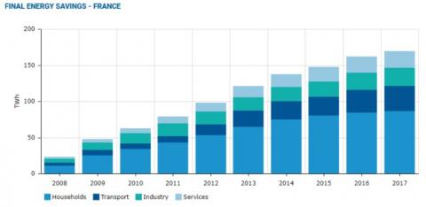
The residential sector remains the largest consumer of electricity in France (44%). However, it is also the sector with the greatest potential for reducing energy waste. The Figure 1 shows that the residential sector has achieved more reductions than other sectors: 86.977 TWh in 2017 [1]. This calculation is done annually compared to the previous year using the ODEX index.
The ODEX is an energy efficiency index that calculates a weighted average of the sub-sector indices for each sector. These sub-sectors are industry, service sector, household end-use or transportation. Changes in the unit energy consumption indicators are used to calculate the indices for each subsector. For households, the calculation considers the main domestic uses for heating and cooking and the largest household appliances such as refrigerators, freezers, washing machines, dishwashers and televisions.
Thermal regulations and tax incentives aimed at reducing greenhouse gas emissions and electricity consumption have made it possible to meet European targets. However, France is still one of the five countries that reduce consumption the least in Europe. In 2017, total energy consumption decreased by 18.5% compared to 2000, while the most efficient country recorded a reduction of 39.1% (Romania) for the same period [1].
Figure 1. Total energy reduction by sector in France
The reduction in energy consumption in the residential sector (28.7%) was greater than in industry (20%) and transport (10.1%) in France. However, electricity consumption per residence remains one of the highest in Europe, at around 2.995 kWh/residence [1].
Consumption habits and energy performance of households are factors influencing these above-average values. France's energy matrix is very different from the rest of Europe, since nearly 70% of cheap electricity comes from nuclear sources [2]. The low cost stimulates the lack of control of over-consumption of electricity by users. Older houses have insufficient thermal insulation to maintain thermal comfort in winter, and have higher indoor temperatures in summer. Therefore, there is a need for more heating and cooling in winter and summer, respectively.
2.2 The energy performance of buildings
Heating represents on average 50% of household electricity consumption in France. And it can reach up to 75% depending on the characteristics of the building [3]. There are currently more than 32.2 million buildings in France with a total consumption of 151.1 TWh in 2017 [2].
Nearly 20 million houses were built before the introduction of the first thermal regulation in 1975 and are very energy consuming. of energy. These houses account for 58% of the housing sector, and account for more than 75% of its energy consumption [4]. Their renovation is therefore made a priority. As part of the "housing renovation plan", a target has been set to reduce final energy consumption by 20% by the end of the year. 2030 and by 50% by 2050, all sectors combined, and primary consumption of fossil fuel energy by 30% by 2030, in addition to the renovation of 500,000 housing per year from 2017 [5]. France also applies its thermal regulation (TR) for all new buildings.
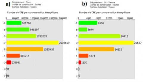
The Energy Performance Diagnosis (EPD) indicates the energy performance of a building by assessing its energy consumption and its impact in terms of greenhouse gas emissions [6].
Figure 2 shows the quantity of licenses issued for the Vienne region and the whole of France. The number of low-energy homes (label A, consumption ≤ 50 kWh/m²/year) in the Vienna region is slightly higher than the national average. However, the energy performance of dwellings predominates in the D label (consumption between 151 and 230 kWh/m²/year), with 34% of the total certificates issued being above the national average.
The residential sector has already made great advances in reducing electricity consumption, as mentioned above. And with the implementation of RT2020 [8], which will encourage all new buildings to be BEPAS (Passive Energy Building) or BEPOS (Positive Energy Building), the targets set to reduce energy consumption by 50% by 2050 will be approached [5].
BEPAS and BEPOS are intelligent buildings that aim to reduce energy losses on the building envelope and on its internal air renewal as much as possible. Insulation, air tightness, and the use of bioclimatic design are therefore very important to improve thermal performance.
BEPAS must have a consumption of less than or equal to 15 kWh/m²/year for heating, domestic water and air conditioning. And the primary energy consumption must not exceed 120 kWh/m²/year. For BEPOS it is still necessary to generate sufficient electricity for the building from one or more renewable energy sources.
Two general strategies are used to improve the energy performance of a building:
In the literature, thermoelectric modules (TEMs) have already been studied in applications to provide benefits in both strategies.
Figure 2. Distribution of EPD by labels: (a) all departments and (b) Vienne [7]
3.1 The thermoelectric effect
The thermoelectric phenomenon combines a hot tank and a reservoir cold, to create a temperature difference, to an electric current. The TEMs are devices capable of using this phenomenon to generate electrical energy (Seebeck effect) or to cool/heat a place (Seebeck effect). Peltier). They are composed of several thermoelectric pairs connected by conductive metal solders pressed between ceramic plates that provide electrical insulation. Each pair is composed of a branch of semiconductor chemically doped for more free electrons (n-leg), and another for more vacant spaces (p-leg). Thus, it is possible for a semiconducting material to conduct an electric current when subjected to the temperature difference.
3.2 Types of thermoelectric devices
As mentioned above, TEMs are versatile devices that can be used in three functions: heating, cooling and power generation. In each of these functions, they are used in combination with other auxiliary devices. In the literature, there are several systems consisting of TEMs and auxiliary devices.
The configuration of the thermoelectric system will depend on the place of application and the chosen cooling medium (air or water). Air cooling is used in most studies because it is cheaper and has a simpler configuration. The most basic system consists of a heat sink with fins and small fans to dissipate the heat. The thermoelectric cooler (TEC) or thermoelectric heater (TEH) is made up of this simple configuration. On the other hand, thermoelectric generators (TEG) can be water-cooled because they can work with warmer temperatures.
Water cooling uses a cooling block, or fins immersed in a fluid stream through a tube, for example. The cooling block has two inlets, one for the cold fluid to enter, and one for the hot fluid to exit after removing heat from the TEM. A pump is used to circulate the fluid.
A new water-cooling prototype is the heat pipe cooling exchanger. This device resembles a thin aluminum plate, which contains many independent microchannel tubes [9].
Song Lv reported, through experimental and simulation tests, that the heat-exchange tube method can produce much higher power and efficiency than the other two methods. For the same module area, water cooling produces higher power and efficiency than air cooling [9].
When calculating the overall efficiency, the consumption of auxiliary devices (fans and pumps) must be considered. The higher the power output, the higher the consumption of the auxiliary equipment [9].
3.3 Domestic places of application of TEMs
Thermoelectric coolers and heaters can be placed on the facade of the house. They are used so that the indoor air exchanges heat with the outdoor air. These systems also act to renew the indoor air. Thermoelectric generators should be placed close to heat sources in the house. The locations available in the home are:
The objective is to recover heat without increasing the consumption of heating, electricity or cooking gas. For this reason, applications in walls and boilers will not be considered.
The heat sources that can be studied are in wet rooms (bathroom and kitchen) and heating/cooking equipment (fireplace and stove).
Three types of systems can be done according to the temperature of the heat source:
(a) Recycling of heat (waste water and exhaust air), low temperature of the heat source (20°C<T<40°C).
(b) Heat recovery at medium temperature (40°C<T<90°C): cooking plate.
(c) High-temperature heat recovery (T >100°C): chimney and wood stove.
Systems (a) and (b) will be able to use the same types of TEG and thermoelectric material (rather Bi2Te3). System (c) can be studied with segmented legs, so the two materials will have to be chosen to compose this TEG.
3.4 Advantages of thermoelectric devices
The cooling system with TECs has several advantages over conventional cooling systems. They do not require refrigerants that are toxic to the environment and emit greenhouse gases (CFCs), like vapor compression systems. They have no moving parts and do not require regular maintenance, which makes them more reliable and robust, and are quieter. On the other hand, the coefficient of performance (COP) and efficiency of this system are significantly lower than conventional systems. Thermoelectric generators have an even greater advantage by using waste heat as a heat source.
3.5 Optimized module design
A single thermoelectric module can be used for both air conditioning and power generation. However, the parameters for achieving better performance in each use are different. Therefore, the optimal geometry will be different for the two uses. But this does not mean that a TEG cannot be used for cooling or a TEC for power generation. In fact, they would perform much less well if they were used in a different function than the one, they were designed for.
In heat recovery applications, it is not necessary to consider the cost of bringing heat from the heat source to the TEG. This is an amount of thermal energy that would be released to the environment.
Therefore, in the design of a GEP, it is preferable to have a high power-factor, even with some reduction in efficiency [10]. The chosen design point should be somewhere between maximum power and maximum efficiency [11]. The height of the thermoelement legs is the most influential parameter in MMT performance [12]. Nuwayhid shows that a reduction in length while maintaining the same leg cross-section would result in an increase in energy production [11].
The maximum power is obtained on a leg length that depends on the temperature difference and is optimized on very short lengths. On the other hand, efficiency is higher for longer leg lengths [11]. Practical design requires a compromise between maximum power and maximum efficiency.
On the other hand, thermoelectric coolers must have a higher efficiency and COP, resulting in a higher cooling capacity. Therefore, thermoelements for this application must have legs of a relatively higher height than in the previous case.
In recent years, TRNSYS has been used in studies on the energy needs of buildings and the performance of air-conditioning and power generation equipment, and the use of renewable energies such as solar energy can also be studied. However, TRNSYS has been little used to study the performance of thermoelectric modules in residences. The simulation of energy and cooling requirements can be done over one year by considering transient or steady state [13-15]. The TRNSYS can also simulate only the device as it was done by Massaguer et al. [16, 17].
It can be used to numerically simulate an office room [13], a prototype in a ventilation box for cooling a room [1] or to study only the performance of an insulated device, or applied to a set of three modules in a pipe for waste heat recovery [16, 17].
Although TRNSYS is a very useful tool for the calculation and evaluation of energy needs in a transitional regime, according to the above studies, there is no not able to solve the heat diffusion equations, and thermoelectric sensors in the software's own resolver. The above studies have so use Matlab and Fortran to solve these equations. The method of finite differences used in combination with the Newton-Raphson method a was used by Massaguer et al. to discretize the model studied [16, 17].
Thermoelectric modules have been studied as Thermoelectric Heating, Thermoelectric Cooling and Thermoelectric Generator in analytical or experimental studies.
4.1 The TRNSYS simulation engine
TRNSYS is a system with a modular structure, capable of describing complex systems with different types of components from its library. The TRNSYS environment consists of two sub-programs: TRNSYS Simulation Studio and TRNBUILD. The first one is the main structure where dynamic simulations can be implemented. The second is the multi-zone interface where building characteristics can be defined.
In Simulation Studio, the components of a project can be linked graphically. These components are available in libraries and are described by mathematical models. It is also possible to use components that connect with external software. Each component of the TRNSYS has a specific number (Type) and a set of proforma. The proforma is the description (black-box) of the input and output parameters of a component.
The studies mentioned above used Matlab to perform the Thermoelectric calculations using the module Type 155. Other programs external can also be connected to TRNSYS as Excel (Type 62), Mathis (Type 159) and Python (Type 163). To use the Matlab mechanism a connection is established in a separate process. A COM interface (Component Object Model) is used for the routine of the Fortran se communicate with Matlab. Type 155 can be called either by an iterative, or by a real-time controller.
In the TRNSYS libraries, there are still three components which differentiate: Type 78a for constant matrices, Type 78b for matrices variables and Type 83 for differentiation. Type 83 calculates the derivative of a signal based on the value of the previous step and can integrate up to 100 variables. The matrix components calculate x for x_dot = A*x + B*U, where U is a vector composed of the list of input data, A and B are matrices constants read from an external file.
4.2 Multi-zone building modeling
The TRNBUILD describes the characteristics of the building such as thermal zones, wall composition, windows, orientation in relation to the sun, infiltration, heating, cooling, etc.
Type 56 is the component responsible for representing the mathematical models, assumptions and characteristics of the multi-zone building that have been described in the TRNBUILD interface. This component can be used in Simulation Studio to simulate thermal and electrical energy requirements throughout the year using meteorological data. Equipment can also be added to interact with these multi-zone buildings.
Environmental characteristics such as sky temperature (Type 69), solar radiation (Type 16), air speed (Type 642) and weather conditions (METEONORM) can be connected to the multi-zone component. This can be done to evaluate the thermal model of the different thermal zones in relation to energy requirements, temperatures and power use, as well as thermal comfort for the users.
4.3 Modeling a TEG on TRNSYS
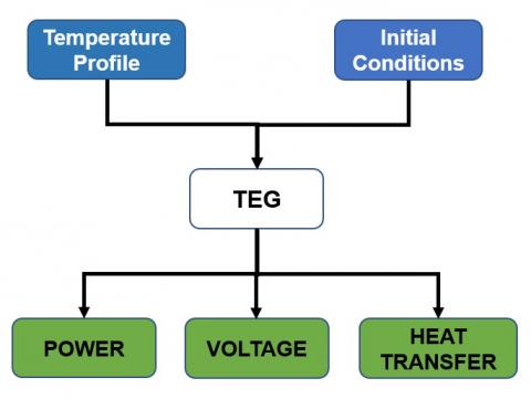
The mathematical model will be solved with matlab, while the TRNSYS will be used to analyze the input and output data of the thermoelectric module array. For this purpose, a new component will have to be created to represent the TEG.
Figure 3. Diagram of the numerical simulation of a TEG on TRNSYS
In Figure 3 each component will represent parameters and properties of the TEGs. The temperature profiles and initial conditions will be inserted into the component as input data. The Initial Conditions component contains the ambient temperature, the mass flow rate and the convection coefficients of the cold and warm side. Power, voltage and heat transfer will be analyzed in this model.
As explained above, thermoelectric modules have a great potential to be used in residences. They can be applied in several places in a residence in order to use them in new BEPAS or BEPOS buildings in the New-Aquitaine region. An optimization of the geometry of the TEM in each application is needed in order to generate more power and to have more cooling power when used as air conditioning.
Running numerical simulations to estimate the amount of energy generated through TRNSYS is possible to validate the analytical results. It will be possible to evaluate the thermal and electrical performance of the thermoelectric modules and estimate the cost-effectiveness of the TEMs in each application.
The authors acknowledge European Union and Region Nouvelle Aquitaine for the research funding in the framework of the program CPER FREDER Bâtiment Durable 2014-2020.
[1] Overall Energy Saving Rate Since 2000, Odyssee Indicators. https://www.indicators.odyssee-mure.eu/energy-saving.html, accessed on June 01, 2020.
[2] L’électricité dans le secteur résidentiel, EDF. https://www.edf.fr/groupeedf/espaces-dedies/l-energie-de-a-a-z/tout-sur-l-energie/ledeveloppement-durable/l-electricite-dans-le-secteur-residentiel.
[3] Ministère de la transition écologique et solidaire. https://www.ecologique-solidaire.gouv.fr/, accessed on May 22, 2020.
[4] Sunvalor – Sbh France, Energy Efficiency in France Ee in Buildings, INDUSTRY & NAVAL. 2014, accessed on May 28, 2020.
[5] MINISTÈRE DE LA TRANSITION ÉCOLOGIQUE ET SOLIDAIRE, Concertation sur le plan rénovation énergétique des bâtiments. nov. 2017.
[6] Diagnostic de performance énergétique - DPE, Ministère de la transition écologique et solidaire. https://www.ecologique-solidaire.gouv.fr/diagnostic performance-energetique-dpe, accessed on May 18, 2020.
[7] Répartition des DPE par type de batiment, Observatoire DPE. https://www.observatoire-dpe.fr/index.php/graphique/dpeParEtiquette, accessed on May 27, 2020.
[8] LE GUIDE DE LA RE 2020, La RT22020. http://www.rt-2020.com/, accessed on May 31, 2020.
[9] Lv, S., He, W., Jiang, Q.Y., Hu, Z.T., Liu, X.H., Chen, H.B., Liu, M.H. (2018). Study of different heat exchange technologies influence on the performance of thermoelectric generators. Energy Convers. Manag., 156: 167-177. https://doi.org/10.1016/j.enconman.2017.11.011
[10] Rowe, D.M., Min, G. (1998). Evaluation of thermoelectric modules for power generation. J. Power Sources, 73(2): 193-198. https://doi.org/10.1016/S0378-7753(97)02801-2
[11] Nuwayhid, R.Y., Rowe, D.M., Min, G. (2003). Low cost stove-top thermoelectric generator for regions with unreliable electric supply. Renew. Energy, 28(2): 205-222. https://doi.org/10.1016/S0960-1481(02)00024-1
[12] Ji, D.X., Wei, Z.B., Mazzoni, S., Mengarelli, M., Rajoo, S., Zhao, J.Y., Pou, J., Romagnoli, A. (2018). Thermoelectric generation for waste heat recovery: Application of a system level design optimization approach via Taguchi method. Energy Conversion and Management, 172: 507-516. https://doi.org/10.1016/j.enconman.2018.06.016
[13] Allouhi, A., Boharb, A., Ratlamwala, T., Kousksou, T., Amine, B.M., Jamil, A., Msaad, A.A. (2017). Dynamic analysis of a thermoelectric heating system for space heating in a continuous-occupancy office room. Applied Thermal Engineering, 113: 150-159. https://doi.org/10.1016/j.applthermaleng.2016.11.001
[14] Irshad, K., Habib, K., Thirumalaiswamy, N., Saha, B.B. (2015). Performance analysis of a thermoelectric air duct system for energy-efficient buildings. Energy, 91: 1009-1017. https://doi.org/10.1016/j.energy.2015.08.102
[15] Irshad, K., Habib, K., Basrawi, F., Saha, B.B. (2017). Study of a thermoelectric air duct system assisted by photovoltaic wall for space cooling in tropical climate. Energy, 119: 504-522. https://doi.org/10.1016/j.energy.2016.10.110
[16] Massaguer, E., Massaguer, A., Montoro, L., Gonzalez, J.R. (2015). Modeling analysis of longitudinal thermoelectric energy harvester in low temperature waste heat recovery applications. Applied Energy, 140: 184-195. https://doi.org/10.1016/j.apenergy.2014.12.005
[17] Massaguer, E., Massaguer, A., Montoro, L., Gonzalez, J.R. (2014). Development and validation of a new TRNSYS type for the simulation of thermoelectric generators. Applied Energy, 134: 65-74. https://doi.org/10.1016/j.apenergy.2014.08.010