OPEN ACCESS
A sustainable substitute to traditional energy conversion systems to supply energy standards to distributed communities by using locally available resources is micro Combined Heat and Power generation(m-CHP) based on biomass gasification. The circular economy concept, whose need is nowadays rising due to the increasing concerns about the release of greenhouse gases (GHGs) emissions and the connected effects on climate changes, is today intensely incentivizing the use of organic waste material for energy purposes. The proposed work focuses on the possible improvements to be made to an existing micro Combined Heat and Power (m-CHP) unit, manufactured by Costruzioni Motori Diesel S.p.A. (CMD). This system, the CMD ECO20, integrates a downdraft gasifier, syngas cleaning devices, a spark ignition engine linked to an electric generator, and two heat exchangers for the waste heat recovery: a plate heat exchanger along the engine cooling circuit and a shell and tube one along the exhaust gases line. The optimization regards the whole heat recovery system in terms of evaluating the possible uses of the energy content of exhaust gases. The use of a numerical model is presented in this paper, relevant to the direct drying process, made thanks to the use of a 0D model of the Thermoflex™ software. The drying of the poplar woodchip with different intrinsic moisture percentages is analysed and a parametric analysis is made by varying the exhaust mass flow rate. To calibrate the model, an experimental characterization is made on the CMD ECO20 by using thermocouples, pressure and mass flow rate sensors along the whole plant.
micro combined heat and power, waste heat recovery, biomass
Combined heat and power generation (CHP) fueled by biomass is one of the most significant alternative technology to respect the environment and save energy, especially in small-scale plants [1]. Biomass availability, indeed, does not depend on climate, like other renewables, and it is carbon dioxide neutral [2]. It suits better to small-scale plants, due to its fast deterioration in humid environments and the related engine difficulties in its storage. An alternative to biomass direct combustion is gasification [3]. Different technologies have been developed in the past years. Among them, systems based on gas engine are able to provide a higher power efficiency and reliability with respect to gas turbine. The residual energy content in the exhaust gases is still high and can be used to transfer heat for the production of hot water [4], in different bottom cycles [5], in power steam cycles [6] or in absorption refrigeration systems [7]. The here presented work is aimed at the development of a numerical model of the thermal recovery process to be need for optimization purposes and the highest reduction of overall losses. The residual energy of exhaust gases is calculated and its usage as a heat transfer fluid for the direct pre-drying of biomass is also analyzed. A parametric analysis is made by varying the initial moisture of the biomass and the exhaust gas-biomass mass flow ratio and the numerical model made through the Thermoflex™ environment is used. Biomass direct drying is one of the most efficient method to increase the lower heating value of the resulting syngas. Indeed. high value of moisture content causes a lower gasification efficiency, because of the greater energy requirement for evaporation. The lower reaction temperature result in a poorer quality product gas with higher levels of tar [8]. A spontaneous drying could occur during storage, depending on the weather conditions and the location of the storage unit. Therefore, the initial moisture content of biomass is extremely variable and an initial drying is compulsory to reduce fluctuations and obtain the same performance of the m-CHP unit.
The analyzed system is the CMD ECO20 micro-CHP unit. It is an automated plant, in which the biomass is gasified in a downdraft gasifier, and the resulting syngas is used, after cleaning and cooling, to power a spark-ignition engine. Heat recovery is achieved through two heat exchangers. First, the secondary circuit exchanges heat in a plate heat exchanger with the engine cooling circuit and, then, in a shell and tube heat exchanger with the exhaust gas circuit. Biomass is pre-dried in the upper part of the gasification reactor. A more precise description of the system is given by authors in a previous paper [4]. To characterize the entire ECO20 system, the plant, equipped with type k thermocouples, pressure sensors and flow rate sensors, installed in specific points, was monitored for a whole day to study its effective heat recovery capability. The biomass flow rate was estimated by measuring the amount of biomass loaded in the hopper and the time needed to consume it all. The ash and condensate flow rates were instead estimated by measuring the amount of ashes collected in the bins and the amount of condensates collected at the discharge of the various components of the plant. Syngas was collected in bags and its composition was measured in laboratory using a gas chromatograph. Exhaust gases composition was analyzed online, during the real operation of the plant, thanks to a portable network device.
2.1 Energy balance
The inputs and outputs energy flows of the system are estimated to evaluate in order all the energy losses of the plant. The estimations of the specific heat (cp) of the syngas and exhaust gases are needed to determine the thermal power available on the hot side of the heat exchangers (1). Biomass lower heating value (LHV) is calculated using a PARR 6200 calorimeter with a Mahler calorimetric bomb.
$\dot{Q}_{{Available}_{Heat Recovery}} =\dot{Q}_C+\dot{Q}_{SYN}+\dot{Q}_F$ (1)
where:
$\dot{Q}_C$ is the energy content of the engine cooling water;
$\dot{Q}_{SYN}$ is the power given by the syngas in the cooler;
$\dot{Q}_F$ is the power transferred by the exhaust gases in the shell and tube heat exchanger.
2.2 Analyzed feedstock
For the experimental study, the syngas derived from poplar woodchip, whose analyses are reported in Table 1, is used. Proximate analysis is made according to reference standards ASTM D 5142 and ultimate analysis is made according to ASTM D 5373.
Table 1. Proximate and ultimate analysis of used feedstock
|
Type of Analysis |
Physical or Chemical Properties |
Sample |
|
Proximate Analysis |
Moisture [%] |
11.2 |
|
Fixed Carbon [%] |
14.8 |
|
|
Volatiles [%] |
73.6 |
|
|
Ash [%] |
0.5 |
|
|
Ultimate Analysis (Dry Basis) |
Carbon [%] |
45.2 |
|
Hydrogen [%] |
5.6 |
|
|
Oxygen [%] |
48.7 |
|
|
Nitrogen [%] |
0.0 |
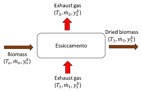
The direct drying process can be summarized according to an open system approach, as shown in Figure 1. Wet biomass enters the system in section 0 and it is hit by a flow of exhaust gases coming from section 1 and exiting through section 2, and totally or partially dried biomass exits section 3.
Figure 1. Direct drying process
The input data required for the Thermoflex™ model are the temperature $T^0$ and the mass flow rate $\dot{m}^0$ of biomass, temperature $T^1$ and the mass flow rate $\dot{m}^1$ of exhaust gases, proximate and ultimate analysis of biomass $y_k^0$ and composition of exhaust gases $y_k^1$.
Thermoflex™ gives as output the drying efficiency, the biomass final temperature ($T^3$) and the thermal power transferred.
The whole system is in stationary conditions and biomass is chemically inert, so it crosses the drying section without reacting. All the moisture content present in the wet biomass is considered as free water, so that the biomass can be completely dried. The exhaust gases are instead considered ideal gases.
Since biomass is chemically inert, the biomass organic fraction and biomass organic and inorganic mass flow rate, remain unvaried from section 0 to section 3:
$y_k^{OM,3}=y_k^{OM,0}$ $k=C,H,O,N,S,Cl$ (2)
$\dot{m}^0 y_{INO}^0=\dot{m}^3 y_{INO}^3$ (3)
$\dot{m}^0 y_{OM}^0=\dot{m}^3 y_{OM}^3$ (4)
The fraction of vapor leaving the drying section is equal to its saturation value at the temperature calculated at the exit of this section $y_{H_2 O}^{sat,2}$, that depends on the saturation pressure ($p_{H_2 O}^{sat} (T^2 )$) .
If $y_{H_2 O}^{dry,2}<y_{H_2 O}^{sat,2}$, biomass is completely dried, so:
$y_{H_2 O}^2=y_{H_2 O}^{dry,2}$ (5)
$y_{H_2 O}^3=0$ (6)
If $y_{H_2 O}^{dry,2}>y_{H_2 O}^{sat,2}$, the drying process is incomplete and:
$y_{H_2 O}^2=y_{H_2 O}^{sat,2}$ (7)
$y_{H_2 O}^3=(\dot{m}^0 y_{H_2 O}^0+\dot{m}^1 y_{H_2 O}^1-\dot{m}^2 y_{H_2 O}^2)/\dot{m}^3$ (8)
The ratio β is defined as the ratio between $\dot{m}^1$ and $\dot{m}^0$. A parametric analysis is made evaluating how the heat recovery is influenced by the exhaust gases mass flow rate.
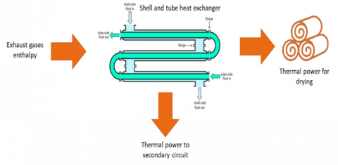
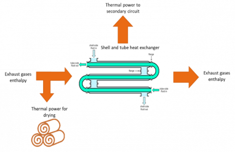
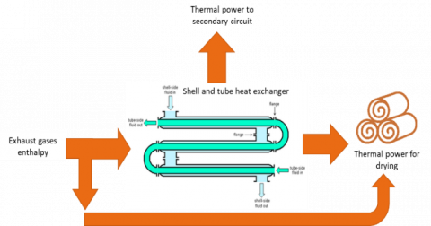
Three cases were analyzed, showed in Figure 2:
a) all the exhaust gases, downstream of the shell and tube exchanger, is used to dry the biomass;
b) a small portion of exhaust gases is taken upstream the shell and tube exchanger and used to dry the biomass.
c) a small portion of exhaust gases upstream the shell and tube exchanger is mixed with the remaining flow downstream the shell and tube exchanger and used to dry the biomass.
For case (b) and case (c), a spilled ratio is defined as the ratio between the exhaust gases mass flow ratio spilled and the total exhaust gases mass flow ratio.
(a)
(b)
(c)
Figure 2. Energy flux for each of the analyzed cases
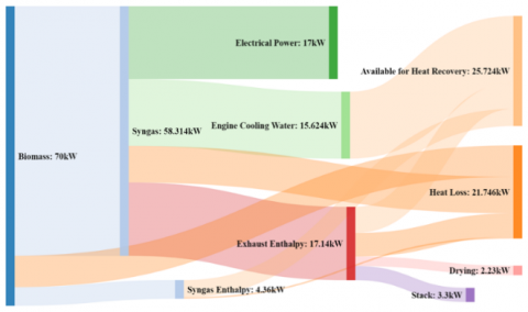
The experimental characterization of the CMD ECO20 allows evaluating the average values of temperature, pressure and mass flow rates in different sections of the plant, as reported in the following Table 2, as well as the evaluation of the thermal power available, shown in the Sankey Diagram of Figure 3.
Table 2. Average values in baseline condition
|
Patm |
1022.44 mbar |
|
TB |
23.46 °C |
|
$\dot{m_B}$ |
18.53 kg/h |
|
$\dot{m_F}$ |
106.62 kg/h |
|
$\dot{m_S}$ |
0.193 kg/h |
|
TS,SH,IN |
67.85 °C |
|
TS,SH,OUT |
78.76 °C |
|
TF,SH,IN |
315.9 °C |
|
TF,SH,OUT |
126.02 °C |
The total heat recovery of the plant is 25.72 kW, which 17.14kW is the exhaust enthalpy available for the biomass drying.
Thanks to the Sankey Diagram, it is possible to calculate the electrical and thermal efficiencies of the plant in baseline case that are, respectively, 24.3% and 36.7%. The greatest heat loss is from the gasification process, where almost 17% is wasted away.
Figure 3. Sankey Diagram of CMD ECO20 in baseline case
For each of the three cases, an initial moisture of 30 % of the biomass is considered. The thermal power transferred to the biomass $\dot{Q}_{B,DRYING}$, sum of the latent and sensible ones, is calculated, as well as the drying efficiency, the residual percentage of moisture and the effective thermal power transferred to the secondary circuit $\dot{Q}_{F,SH}$, as reported in Table 3.
Table 3. Average temperature, pressure and mass flow rate values
|
Quantities |
Case (a) |
Case (b) |
Case (c) |
|
Spilled ratio |
0 |
0.1 |
0.1 |
|
$\dot{m}_{F,SH}$ (kg/s) |
0.03 |
0.027 |
0.027 |
|
$\dot{m}^1$ (kg/s) |
0.03 |
0.003 |
0.03 |
|
$T^1$ (°C) |
119 |
316 |
139.3 |
|
$t^3$ (°C) |
48.26 |
55.39 |
49.4 |
|
$\dot{Q}_{B,LATENT}$ (kW) |
2.08 |
0.45 |
2.45 |
|
$\dot{Q}_{B,SENSIBLE}$(kW) |
0.29 |
0.36 |
0.30 |
|
$\dot{Q}_{B,DRYING}$ (kW) |
2.37 |
0.82 |
2.75 |
|
Drying efficiency (%) |
56.5 |
12.5 |
66.5 |
|
Final moisture of biomass (%) |
15.7 |
27.27 |
12.55 |
|
$\dot{Q}_{F,SH}$ (kW) |
8.80 |
5.63 |
5.63 |
Case (a) have a higher thermal power transferred to the secondary circuit (+40 %) than the case (b) and case (c), even though the thermal power for drying process is lower than case (c) by 14.4 %. Case (c) is the best solution to maximize the thermal power for drying process.
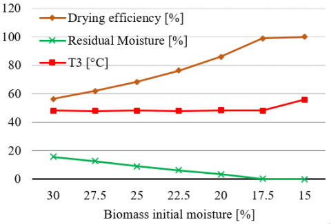
Two parametric analyses are carried out for the case (a) varying the percentage of moisture in the used feedstock and the value ofβ, in order to evaluate the exhaust gas drying efficiency and biomass final temperature. Results are reported in Figures 3 and 4. With a biomass initial moisture of 17.5, the drying efficiency reaches its maximum and the final temperature of biomass starts to increase.
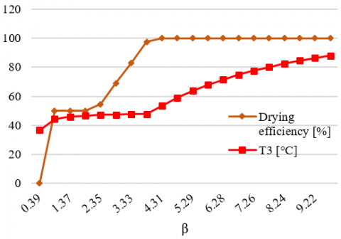
By looking at Figure 5, instead, it can be noted that for β<1 the drying efficiency is very low, then it increases for β>1 until it reaches the maximum value at β=4.31, or for a flow rate of exhaust gases equal to 0.022 kg/s. The evaporation process takes place at almost constant biomass temperature. When the flow rate of drying agent determines an evaporation ideally higher than 100 %, the remaining thermal power is spent to increase the biomass enthalpy, and therefore its temperature.
Figure 4. Parametric analysis varying the initial moisture
Figure 5. Parametric analysis varying the β
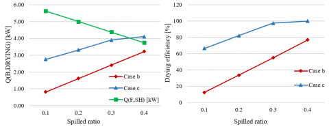
A third parametric analysis is made for case (b) and case (c) by varying the spilled ratio up to 0.4. The parametric analysis, shown in Figure 6, shows the thermal power transferred to the secondary circuit and the thermal power transferred to biomass, in order to search for the best spilled ratio.
In both cases, if increases the spilled ratio, the thermal power to secondary circuit reduces drastically, while the thermal power transferred to the biomass and the drying efficiency increases.
In Figure 6, it can be seen that for all spilled ratio, case (c) has a higher drying efficiency on respect case (b).
Indeed, it is always better to spill a small portion and remix with the remaining exhaust mass flow rate.
Figure 6. Parametric analysis varying the spilled ratio
In this work a thermodynamic analysis is applied to the micro-CHP CMD ECO20 system and an evaluation of the exhaust gases energy content is made, with the aim of using a part to fit to dry the same biomass being processed. The following conclusions can be drawn:
(1) Increasing the exhaust gas mass flow rate increase the drying efficiency. The evaporation process is isothermal until drying efficiency reaches the 100 %; then, also the biomass temperature increases;
(2) The best solution to maximize the drying potential is to take a small portion (10 %) of exhaust gases upstream of the shell and tube exchanger and mixing it with the remaining flow downstream the shell and tube exchanger;
(3) Increase the spilled ratio increases the drying efficiency. For case (c), the drying efficiency of 100 % is reached for a spilled ratio of 0.3.
|
CHP |
Combined heat and power |
|||
|
cP |
specific heat, J. kg-1. K-1 |
|||
|
LHV |
Lower heating value, J.kg-1 |
|||
|
$\dot{m}$ |
Mass flow rate, kg. s-1 |
|||
|
$\dot{Q}$ |
Thermal output, W |
|||
|
T |
Temperature, K |
|||
|
y |
Mass fraction |
|||
|
Greek symbols
|
|
|
||
|
$\beta$ |
Exhaust gas mass flow rate-to-biomass mass flow rate ratio |
|
||
|
Subscripts
|
|
|
||
|
0 |
Section of wet biomass |
|
||
|
1 |
Enter section of exhaust gases |
|
||
|
2 |
Exit section of exhaust gases |
|
||
|
3 |
Section of dried biomass |
|
||
|
Atm |
Atmospheric, bar |
|
||
|
B |
Biomass |
|
||
|
C |
Engine cooling water |
|
||
|
F |
Exhaust gases |
|
||
|
H2O |
Water |
|
||
|
k |
k-component |
|
||
|
IN |
Inlet |
|
||
|
INO |
Inorganic |
|
||
|
OM |
Organic Matter |
|
||
|
OUT |
Outlet |
|
||
|
S |
Secondary circuit |
|
||
|
SH |
Shell and tube exchanger |
|
||
|
SYN |
Syngas |
|
||
[1] Ahrenfeldt J, Thomsen TP, Henriksen U, Clausen LR. (2013). Biomass gasification cogeneration–A review of state of the art technology and near future perspectives. Applied Thermal Engineering 50(2): 1407-1417. https://doi.org/10.1016/j.applthermaleng.2011.12.040
[2] Dong L, Liu H, Riffat S. (2009). Development of small-scale and micro-scale biomass-fuelled CHP systems–A literature review. Applied Thermal Engineering 29(11-12): 2119-2126. https://doi.org/10.1016/j.applthermaleng.2008.12.004
[3] Lapuerta M, Hernández JJ, Pazo A, López J. (2008). Gasification and co-gasification of biomass wastes: Effect of the biomass origin and the gasifier operating conditions. Fuel Processing Technology 89(9): 828-837. https://doi.org/10.1016/j.fuproc.2008.02.001
[4] La Villetta M, Costa M, Cirillo D, Massarotti N, Vanoli L. (2018). Performance analysis of a biomass powered micro-cogeneration system based on gasification and syngas conversion in a reciprocating engine. Energy Conversion and Management 175: 33-48. https://doi.org/10.1016/j.enconman.2018.08.017
[5] Liu JP, Fu JQ, Ren CQ, Wang LJ, Xu ZX, Deng BL. (2013). Comparison and analysis of engine exhaust gas energy recovery potential through various bottom cycles. Applied Thermal Engineering 50(1): 1219-1234. https://doi.org/10.1016/j.applthermaleng.2012.05.031
[6] Fu J, Liu J, Ren C, Wang L, Deng B, Xu Z. (2012). An open steam power cycle used for IC engine exhaust gas energy recovery. Energy 44(1): 544-554. https://doi.org/10.1016/j.energy.2012.05.047
[7] Manzela AA, Hanriot SM, Cabezas-Gómez L, Sodré JR. (2010). Using engine exhaust gas as energy source for an absorption refrigeration system. Applied Energy 87(4): 1141-1148. https://doi.org/10.1016/j.apenergy.2009.07.018
[8] Brammer JG, Bridgwater AV. (1999). Drying technologies for an integrated gasification bio-energy plant. Renewable and Sustainable Energy Reviews 3(4): 243-289. https://doi.org/10.1016/S1364-0321(99)00008-8