OPEN ACCESS
Phase Change Materials (PCM), being able to supply dynamic thermal capacity due to their relatively high enthalpy of fusion, have largely shown a great potential for energy saving in buildings. Bio-compatible nanostructured shape-stabilized PCMs, with a specifically designed core-shell structure, already reported in a previous work, were studied here, with reference to lightweight constructions, carrying out dynamic simulations, adopting a multi-parametric approach. Suitable figures of merit for thermal comfort indoor were adopted, with this aim.
nanostructured PCMs, sol-gel synthesis, thermal comfort
Phase change materials (PCMs) can store large amounts of latent thermal energy in building components, during phase transition, occurring at their melting temperature (TM) [1-2]. The amount of heat storage depends upon the chemical bonds to be broken across the phase transition at constant pressure. This behaviour may lead to energy saving and improved indoor comfort. The typical classification of PCMs includes organic, inorganic and eutectic [3]. Paraffins, esters, fatty acids and alcohols [4] are organic PCMs whereas salt hydrates and metals are inorganic PCMs [5]. The most relevant properties of PCMs are: latent heat of transition per unit mass, TM, specific heat and thermal conductivity.
In buildings, PCMs can contribute to effectively redistribute thermal loads, by embodying them especially in walls and floor elements [6]. Paraffinic wax embodied in lime plaster enhances heat capacity [7] and opens new chances in building refurbishment [8]. It has been demonstrated that the latent heat storage of a PCM-doped (24 % in mass) plaster can be increased from 0.4 kJ/(kg·K) to about 2.1 kJ/(kg·K), or from against 0.77 kJ/(kg⋅K) to 1.6 kJ/(kg⋅K) [9-10].
In lightweight constructions, PCMs offer the advantage of compensating for the low thermal inertia value of the wall, due to the limited weight of the materials used to fabricate it. In this way, combining the PCMs with thermal insulating materials, it is possible to achieve the double benefit of damping and attenuating the incident thermal wave.
Fiorito [11] used the software platform Energy Plus [12], developed by the U.S. Department of Energy’s Building Technology Office, to simulate the effect of PCMs in a test room, operating without any HVAC system. It was observed that the benefits in terms of indoor comfort (Time non Comfortable hours, according to ASHRAE 55-2010 adaptive thermal comfort model) were proportional to the thickness of PCM layer, but only up to 6 cm and that in very well insulated buildings the thermal insulation lowers the effectiveness of PCMs, if used in the innermost layers.
In another work, hydrated salt, melting at about 28 °C, was encapsulated in specially designed containers having a size of 1 mm to be embodied in PCM-enhanced frame walls, in California. Energy saving of 9.21 kWh/(m2·yr) were achieved [13]. Navarro et al. [14] demonstrated HVAC system saving between 30 % and 55 %, adopting the slab as a PCM storage unit. To this aim, 52 kg of RT-21 paraffin were used, encapsulated within 1456 aluminium tubes, with a diameter of 12 mm. A large number of studies have appeared, employing paraffin as a PCM [15], for its suitable TM but also its relatively high latent heat (244 kJ/kg). Anyway, it has been observed that the widespread usage of PCMs in constructions is linked to narrower temperature range of the phase change process as well as a reduction of process costs [16]. In this roadmap, the advantage of nanoscale effects might improve thermo-physical and physicochemical properties, offering the chance to exploit Nano-enhanced features of PCM materials. Several research activities are currently working on this challenge [17]. Nano-enhanced PCMs can include certain amounts of dispersed nanomaterials to improve some figures of merit, such as a low value of thermal conductivity [2]. Copper, titania, alumina, silica and zinc oxide nanoparticles (NPs) have been used as additivies in PCMs and underwent thermal investigations [18], showing that the highest increase of thermal conductivity and latent heat storage in paraffins can be attained by using titania NPs. That work concluded that a detailed risk assessment should be considered when using Nano-enhanced PCMs in buildings and that further work is still needed to explore the effect of NPs in thermal conductivity of PCMs, in order to understand the intermolecular interaction standing at the basis of the performance enhancement, involving molecular and macroscopic scales.
A completely different route towards Nano-enhanced PCMs is represented by their encapsulation within Nano-shells [19] or nanofibers [20]. Leakage in the liquid phase can be avoided by designing suitable processes of shape-stabilization via micro- or Nano-encapsulation, effecting an increase of heat transfer depending on the larger available surface area of micro- and nanoparticles, compared to microcapsules [21]. The first positive effects of Nano-encapsulation are to provide shape-stabilization and protect of PCMs from the surrounding environment. Nano-PCMs can be obtained by different synthetic routes, ranging from sol-gel to mini-emulsion, emulsion and in situ polymerization [22]. For instance, polystyrene and n-heptadecane micro-/Nano capsules were synthetized by emulsion polymerization route. The small capsules ranged from 10 nm to 40 nm [23]. With the aim to encapsulate PCMs in Nano-shells, amorphous silica is a material with several advantages: compatible values of high heat storage capacity and thermal conductivity [24], bio-compatibility and non-toxicity for living organisms and the environment [25-26]. Silica shells can effectively host PCMs within their core [27].
Silica spheres with n-octadecane core (melting between 23 and 28 °C) were synthesized using an inorganic precursor (TEOS) in a sol–gel process [28]. Belessiotis et al. [29] reported silica shells embodying a paraffin core: these structures were obtained via sol gel method, with a latent heat of about 156 kJ/kg. Latibari et al. [30], in the other hand, reported silica Nano-shells with palmitic acid core, adopting a multistep sol-gel method. The efficiency of encapsulation, (i.e. the percent ratio between the latent heat of the encapsulated PCM and that of the pure PCM) varied from 83.25% to 89.55 %. In that work, nanoparticle size ranged between 183.7 nm and 722 nm. The relatively high TM of the palmitic acid (61°C) does not make them good candidates for the application in buildings.
Not only TM influences the choice of a good PCM for use in buildings also their cost plays a significant role. According to Kosny et al. [31], a cost-effective PCM with a latent heat as high as 116 kJ/kg should be projected to be 4.4-6.6 USD/kg. In this roadmap, the exploitation of nanoscale effect, to enhance process costs and reduce the use of raw materials, could be significant.
PCMs for building applications should be produced by means of environmental-friendly processes and raw materials. For example, paraffins are inflammable and probably carcinogen (source: Sigma-Aldrich). Other materials, like Polyethylene-glycol-600 (PEG600), are biocompatible, inert, water soluble, inexpensive and quite prone to customizing nanostructures [32]. PEG600 is used in the biomedical field, according to Food and Drug Administration for many applications [33]. Moreover, the TM is around 20-22°C (Source: Sigma-Aldrich), well compatible with the range of comfortable indoor temperatures.
In a previous work [34], we designed, synthesized and characterized SiO2@PEG600NPS with a diameter of (300 ± 15) nm, adopting a one step and highly reproducible route. The full physical, chemical, thermal and morphological characterization preceded an in vitro toxicological assessment. The latent heat storage capacity, expressed by an enthalpy of 66.24 kJ/kg within a tight TM range, centered at 20-21°C, make them reliable shape-stabilized Nano-PCMs for thermal energy storage in building applications. The thermal figures of merit of this newly conceived Nano-PCM were used in that work as an input to perform simulations in order to demonstrate the attainable energy savings consequent to the integration of certain percentage of SiO2@PEG600 NPS (50 %) within building gypsum plasters. To this aim, we compared a reference apartment to one equipped with the proposed material applied over all internal and horizontal plastered surfaces.
The idea behind the present work is to verify the applicability of this novel material in buildings characterized by light envelopes, at different levels of thermal insulation. For this purpose, we obtained the energy consumption for HVAC occurring on an annual basis and the consequent reduction, following the use of Nano-PCM in different locations (Milan, Brindisi, Riyadh). Afterwards, the effect of PCM on the number of hours of comfort on the winter season was verified, according to standard EN 15251 [35].
2.1 Nano-PCM synthesis and characterization
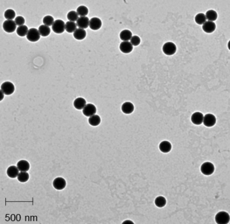
The encapsulation of PEG600 (1mM) in a silica shell was carried out following the so called Stöber method [36] with some modifications obtaining monodispersed NPs with a size of about 300 nm [34]. A JEOL Jem 1011 microscope (JEOL USA, Inc), operating at an accelerating voltage of 100 kV, was used to make TEM characterizations: 10 µl of solution containing NPs dispersed in water were dropped on carbon-coated copper grids (Formvar/Carbon 300 Mesh Cu) (Figure 1).
Figure 1. Representative TEM image of SiO2@PEG600 NPs
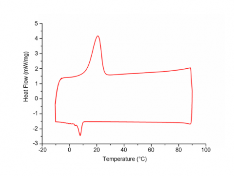
Figure 2. Differential scanning calorimetry (DSC) curve
Melting/freezing temperatures and enthalpies of fusion for SiO2@PEG600 were measured by Differential Scanning Calorimetry (DSC) (Mettler Toledo 822, Greifensee, Switzerland), obtaining a thermogram reported in Figure 2. The analysis was performed on dried samples at atmospheric pressure under a constant stream of nitrogen (60 mL·min-1). A first isothermal step at -10 °C for 5 minutes was applied, followed by a heating scan between -10 °C and 90 °C at 1 °C·min-1. Successively, a sequential isothermal step at 90 °C for 5 minutes, followed by a cooling scan from 90 °C to -10°C at 1°C·min-1 were recorded.
The SiO2@PEG600 showed a melting point of about 21 ̊C. The integration of area under the peaks vs time was used to measure the enthalpies value of SiO2@PEG600 (Figure 2), that was 66.24 kJ/kg.
Furthermore, viability assay and morphological analysis were also carried out in human adenocarcinoma alveolar basal epithelial cells that mimic an inhalation exposure: results clearly showed the biocompatibility of novel nanostructures, as reported in [34].
2.2 Building models and energyplus simulations
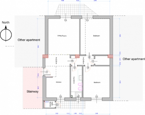
EnergyPlus was used to simulate a typical Italian dwelling (surface area, 78 m2), located in a multi-storey building, with the aim to assess potential benefits deriving from the use of the newly designed nano-PCM. External walls were designed adopting typical stratigraphy of a building envelope with a lightweight structure: external wooden cladding (2 cm), two scenarios of thermal insulation: low (5 cm) and high thermal insulation (10 cm), internal plasterboard panel (5 cm). The same plasterboard layer was considered for all vertical surfaces and also for the ceiling.
Only the North and South walls are involved in heat exchange. In the low insulation scenario, the U-factor (Uf) was Uf=0.46 W/m2K, whereas in the high insulation scenario was Uf=0.26 W/m2K.
Windows used in the model show a glazing system made of two 4 mm panes, divided by a 20 mm argon gap, with U-factor value of Uf=1.98 W/m2K and a frame conductance of 1.2 W/m2K. The internal glass pane was coated with a low emittance layer.
The 3D model of the case study was first made in SketchUp and then exported to Energy Plus v. 8.9, in order to perform the dynamic simulations for the different scenarios. A simplified “Ideal Load Air System” approach, with no outdoor air was considered, in order to assess the heating and cooling energy uses. In this way, Energy Plus strictly provides heating and cooling energy required to meet the temperature value selected for the input set-points (20.5 °C in winter, 26 °C in summer).
Simulations were carried out in cities belonging to as many climatic zones: Brindisi (Hot-summer Mediterranean climate) Milan (Humid subtropical climate) and Riyadh Riyadh (Hot Desert Climate). The heating schedule was adapted to each location, according to the climatic zone they belonged to, depending on national regulations. Thus, in Brindisi heating worked from November 15th to March 31st, with up to 8 hours per day. In Milan it worked from October 15th to April 15th with a maximum of 12 hour per day.
Cooling was considered to be turned on from July 1st to August 31st in all the locations. Envelope thermal resistance was considered the same although climate zones were significantly different.
The external surfaces (horizontal, East-facing and West-facing) were considered adiabatic (though density, heat capacity and conductivity were provided), so as to simulate a room laying in an intermediate floor. For ventilation, windows were supposed to be open half an hour per day (from 7.30 to 8.00) during workdays, and one hour per day during weekends. For fixed openings and windows cracks (up to 0.03 m2 area) an “always on” schedule was applied.
Figure 3. Plan of the apartment used to create the energyplus model
In order to assess the effect of Nano-PCMs on energy uses for HVAC we made simulations in all of the three locations and considering the two insulation scenarios. On the other hand, comfort in thermal environment was estimated according to the approach contained in European Standard EN 15251, which was conceived to be applied in buildings without operating HVAC systems. According to this regulatory document, the thermal comfort zone depends on the outdoor running mean temperature. If the indoor air temperature is outside a specified range (Table 1), depending on the outside temperature, mechanical cooling or heating should be operated and the non-adaptive Fanger comfort model should rather be used to obtain valuable thermal comfort consideration.
Table 1. Categories and limits of the thermal comfort zone, according to EN 15251
|
EN 15251 |
Upper limit of Category III (°C) |
10 °C ≤ f(Tout) |
|
0.33 f(Tout)+18.8+4 |
≤ 30 °C |
|
|
Upper limit of Category II (°C) |
10 °C ≤ f(Tout) |
|
|
0.33 f(Tout)+18.8+3 |
≤ 30 °C |
|
|
Upper limit of Category I (°C) |
10 °C ≤f(Tout) |
|
|
0.33 f(Tout)+18.8+2 |
≤ 30 °C |
|
|
Optimal comfort temperature (°C) |
|
|
|
0.33 f(Tout)+18.8 |
|
|
|
Lower limit of Category I (°C) |
15 °C ≤ f(Tout) |
|
|
0.33 f(Tout)+18.8-2 |
≤ 30 °C |
|
|
Lower limit of Category II (°C) |
15 °C ≤ f(Tout) |
|
|
0.33 f(Tout)+18.8-3 |
≤ 30 °C |
|
|
Lower limit of Category I (°C) |
15 °C ≤ f(Tout) |
|
|
0.33 f(Tout)+18.8-4 |
≤ 30 °C |
Table 2. Specific energy uses for heating and cooling on a yearly basis
|
|
5 cm thick insulation |
10 cm thick insulation |
||
|
Heating energy consumption [kWh/m2.yr] |
Cooling energy consumption [kWh/m2.yr] |
Heating energy consumption [kWh/m2.yr] |
Cooling energy consumption [kWh/m2.yr] |
|
|
MILAN |
|
|
|
|
|
Reference case |
13.04 |
6.01 |
10.83 |
6.10 |
|
PCM |
12.79 |
6.16 |
10.50 |
6.22 |
|
Percent variation (%) |
-2.0 |
+3.0 |
-3.0 |
+2.0 |
|
BRINDISI |
|
|
|
|
|
Reference case |
2.71 |
6.65 |
2.33 |
6.68 |
|
PCM |
2.54 |
6.70 |
2.19 |
6.72 |
|
Percent variation (%) |
-6.0 |
+1.0 |
-6.0 |
+1.0 |
|
RIYADH |
|
|
|
|
|
Reference case |
0.33 |
6.77 |
0.27 |
6.77 |
|
PCM |
0.31 |
6.77 |
0.24 |
6.77 |
|
Percent variation (%) |
-7.0 |
0.0 |
-11.0 |
0.0 |
In table 1, f(Tout) is the prevailing mean outdoor air temperature and is expressed as a function of the daily running mean external temperature (Tout), by means of:
$f({{T}_{out}})={{\theta }_{rm(ed)}}=({{\theta }_{ed-1}}+0.8\cdot {{\theta }_{ed-3}}+0.5\cdot {{\theta }_{ed-4}}+0.4\cdot {{\theta }_{ed-5}}+0.2\cdot {{\theta }_{ed-7}})/3.8$
where $\theta _{ed-n}$ is daily mean outdoor air temperature for n-days prior the day in question.
2.3 Yearly HVAC energy consumption
Table 2 reports the specific energy uses for heating and cooling on a yearly basis, referring to the floor surface unit of the modeled dwelling, in different scenarios. A comparison was made between an apartment containing standard plaster and one equipped with the proposed Nano-PCM, with reference to different insulation scenarios: low insulation (5 cm) and high insulation (10 cm). All the analyses were also referenced to different locations: Milan, Brindisi and Riyadh. Data reported in Table 3 show that the city of Riyadh does not represent a suitable climatic context for the exploitation of the proposed innovative material, as the temperature is generally higher than the PCM TM, throughout the year. The reported 7% savings in heating consumption is actually negligible in terms of absolute value, both in the low and in the high thermal insulation scenario. Reduction of global energy consumption, which is a consequence of the increase in the thickness of the thermal insulation, is also confirmed in this area, although the figure recorded in Milan and Brindisi was much more significant. The best result was achieved in Brindisi, with 6% savings for heating, on an annual basis, both in the low insulation scenario and in the high insulation scenario, with interesting differences in terms of absolute value: the energy uses were lower if insulation layer was 10 cm thick, 2.3 kWh/m2 ·yr in the reference case and 2.2 kWh/m2 ·yr if nano-PCM was used. The same difference was reported in the low-insulation scenario, comparing the reference case and the building equipped with Nano-PCM. Energy consumption for summer cooling in Brindisi was unchanged in the scenario with 10 cm thick insulation. In Milan, the achievable savings in terms of winter heating was substantially offset by a similar increase in summer cooling. The energy consumption reported for the three locations showed that only in Brindisi, due to its climatic conditions, an effective combination was achieved, reaching a convenient compromise between the amount of Nano-PCM to be used in plaster and the thickness of thermal insulation used in the building envelope.
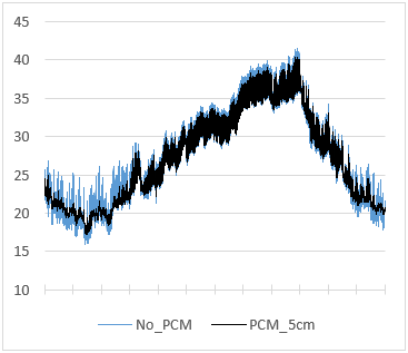
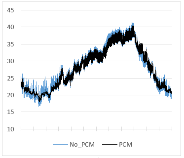
Figure 4a. Annual trend of the internal surface temperature of South-facing wall in the low insulation scenario
Figure 4b. Annual trend of the internal surface temperature of South-facing wall in the low insulation scenario
The above reported considerations on energy consumption led to consider only the climatic location of Brindisi, for the following analyses. The two graphs shown in Figures 4a and 4b report the internal surface temperature of the South-facing wall, in the two insulation scenarios. In detail, Figure 4a compares the surface temperature of the reference wall with the one embodying the Nano-PCM material in the low insulation scenario; Figure 4b shows the same comparison in the high insulation scenario. As can be observed in both graphs, the shift in surface temperatures is significant only in the winter season, when the alternate melting and solidification cycles take place. In winter, in fact, Nano-PCMs embodied in the plaster allow to attenuate the temperature daily changes of surface temperature, while maintaining the value near the comfort temperatures. The remaining seasons show, in a negligible way, the attitude of the material to mitigate the daily temperature range in the surface temperature. These considerations are valid for both thermal insulation scenarios.
2.5 Thermal comfort according to EN 15251
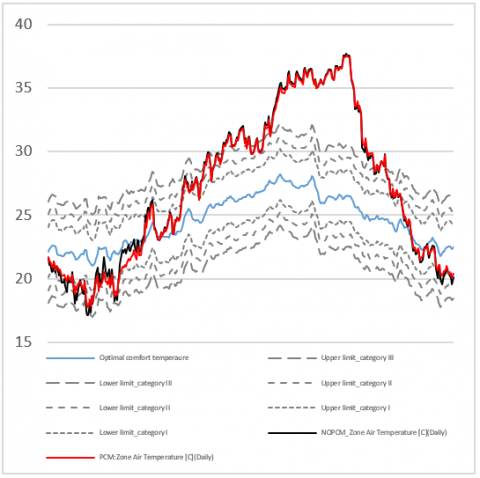
Figure 5a and Figure 5b show the trend of the indoor air temperature on an annual basis, inside the apartment, both in the reference case and in the hypothesis of a building equipped with Nano-PCM. In these graphs, the limits of the three categories of thermal comfort are also reported, with the optimal temperature, calculated according to regulatory document EN 15251.
Figure 5a. Comfort categories I,II and III according to standard EN 15251 and annual trend of indoor daily average air temperature with and without PCMs, in the low insulation scenario
The graph shows that the presence of the Nano-PCM in the plaster tends to contain oscillations of the internal air temperature, keeping it well within the limits of the categories of comfort identified by EN 15251, especially in the winter season.
In particular, it was observed that the air temperature inside the building was within the limits of Category III for almost all the time, and therefore an adaptive strategy could be used, in order to pursue thermal comfort. On the contrary, an adaptive strategy is not usable in the period between the beginning of July to the second decade of October, where the internal air was above 30 °C. The contribution of the PCM was then irrelevant, given the high temperatures, compared to the TM of the PEG600-based Nano-PCM.
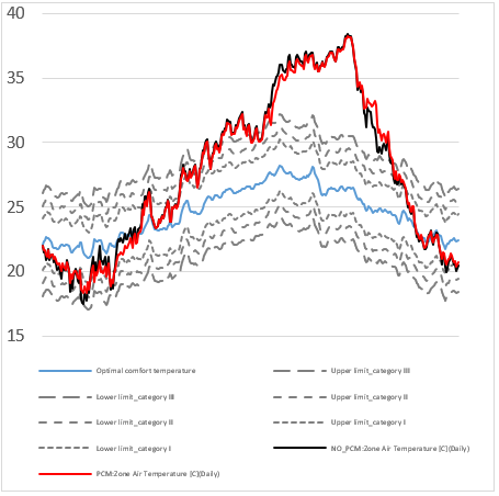
Figure 5b. Comfort categories I,II and III according to standard EN 15251 and annual trend of indoor daily average air temperature with and without PCMs, in the high insulation scenario
Table 3. Winter days in thermal comfort categories, according to European Standard EN 15251
|
|
Days in Category III |
Days in Category II |
Days in Category I |
|
Low insulation |
|
|
|
|
Reference case |
68 |
56 |
35 |
|
PCM |
70 |
63 |
34 |
|
%_change |
+2.9 |
+12.5 |
-2.9 |
|
High insulation |
|
|
|
|
Reference case |
68 |
63 |
48 |
|
PCM |
71 |
66 |
46 |
|
%_change |
+4.5 |
+4.7 |
-4.2 |
Also in this case, the considerations made for the low insulation scenario can be re-proposed for the high insulation
scenario. Indeed, the trend of the curves showed relevant similarities. Eventually, Table 3 reports the number of days in which thermal comfort conditions were detected, according to European standard EN 15251. As it can be observed in both insulation scenarios, the number of days in which the conditions of thermal comfort were achieved indoor tends to be increased.
In particular, the days reporting comfort conditions compatible with Category II and Category III, according to the European standard, tend to increase. Moreover, in both cases, occurrence of comfort conditions defined by category I appeard to be reduced.
It is interesting to observe the total number of days in Category III was increased by 2.9% in the first scenario and by 4.5% in the second scenario. This figure is symptomatic of improved comfort conditions related to the use of Nano-PCM within the wall stratigraphy.
On the other hand, the variations in the number of days in comfort conditions according to Category II and Category I tend to be re-distributed internally, between the same two categories. internally.
This work was divided into two different steps. In the first part, we verified the effect of a newly developed Nano-PCM material on energy uses, considering them embodied in a modeled test light-weight building. To this aim, two different thermal insulation conditions (5 cm and 10 cm thick insulation layers, respectively) were studied. These analyses were carried out with reference to three different cities, Milan, Brindisi and Riyadh, corresponding to as many climatic conditions, in which the material was suitably tested. These activities allowed us to examine the energy consumption on an annual basis for winter heating and summer cooling. The most interesting results were obtained for the location in the temperate Mediterranean climate condition (Brindisi).
Later on, having identified this optimal climatic condition as the one in which it was possible to ideally exploit the features of proposed Nano-PCM, indoor thermal conditions were analyzed, considering the heating and air-conditioning systems deactivated, according to the European standard EN 15251, dealing with adaptive thermal comfort standard. In these conditions, the results of dynamic simulations showed that the effect of Nano-PCMs was significant in the winter season, offering a combined effect, if associated with an optimal thickness of thermal insulation layer (10 cm). The maximum energy saving for heating consumption was found to be 6%, whereas energy use for cooling was almost unvaried.
[1] Kośny J. (2015). An application of phase change materials in building envelopes and internal structures. PCM-Enhanced Building Components. https://doi.org/10.1007/978-3-319-14286-9
[2] Ma Z, Lin W, Sohel MI. (2016). Nano-enhanced phase change materials for improved building performance. Renewable and Sustainable Energy Reviews 58: 1256-1268. https://doi.org/10.1016/j.rser.2015.12.234
[3] Sharma A, Tyagi VV, Chen CR, Buddhi D. (2009). Review on thermal energy storage with phase change materials and applications. Renewable and Sustainable Energy Reviews 13: 318-345. https://doi.org/10.1016/j.rser.2007.10.005
[4] Baetens R, Petter B, Gustavsen A. (2012). Phase change materials for building applications: A state-of-the-art review. Energy and Buildings 42: 1361-1368. https://doi.org/10.1016/j.enbuild.2010.03.026
[5] Su W, Darkwa J, Kokogiannakis G. (2015). Review of solid-liquid phase change materials and their encapsulation technologies. Renewable and Sustainable Energy Reviews 48: 373-391. https://doi.org/10.1016/j.rser.2015.04.044
[6] Mavrigiannaki A, Ampatzi E. (2016). Latent heat storage in building elements: A systematic review on properties and contextual performance factors. Renewable and Sustainable Energy Reviews 60: 852-866. https://doi.org/10.1016/j.rser.2016.01.115
[7] Pavlík Z, Trník A, Ondruška J, Keppert M, Pavlíková M, Volfová P, Kaulich V, Černý R. (2013). Apparent thermal properties of phase-change materials: An analysis using differential scanning calorimetry and impulse method. International Journal of Thermophysics 34: 851-864. https://doi.org/10.1007/s10765-012-1169-1
[8] Ascione F, Bianco N, De Masi RF, de’ Rossi F, Vanoli GP. (2014). Energy refurbishment of existing buildings through the use of phase change materials: Energy savings and indoor comfort in the cooling season. Applied Energy 113: 990-1007. https://doi.org/10.1016/j.apenergy.2013.08.045
[9] Fořt J, Trník A, Pavlík Z. (2014). Influence of PCM admixture on thermal behavior of composite plaster. Advanced Materials Research 1054: 209-214. https://doi.org/10.4028/www.scientific.net/AMR.1054.209
[10] Pavlík Z, Trník A, Keppert M, Pavlíková M, Žumár J, Černý R. (2014). Experimental investigation of the properties of lime-based plaster-containing PCM for enhancing the heat-storage capacity of building envelopes. International Journal of Thermophysics 35: 767-782. https://doi.org/10.1007/s10765-013-1550-8
[11] Fiorito F. (2014). Phase-change materials for indoor comfort improvement in lightweight buildings. A parametric analysis for Australian climates. Energy Procedia 57: 2014-2022. https://doi.org/10.1016/j.egypro.2014.10.066
[12] EnergyPlus. (2018). EnergyPlus 8.9 Building technologies program, U.S. Energy, DOE Energy Effic. Renew.
[13] Lee KO, Medina MA. (2016). Using phase change materials for residential air conditioning peak demand reduction and energy conservation in coastal and transitional climates in the State of California. Energy Build 116: 69-77. https://doi.org/10.1016/j.enbuild.2015.12.012
[14] Navarro L, De Gracia A, Castell A, Cabeza LF. (2016). Experimental evaluation of a concrete core slab with phase change materials for cooling purposes. Energy Build 116: 411-419. https://doi.org/10.1016/j.enbuild.2016.01.026
[15] Zalba B, Marın JM, Cabeza LF, Mehling H. (2003). Review on thermal energy storage with phase change: Materials, heat transfer analysis and applications. Applied Thermal Engineering 23(3): 251-283. https://doi.org/10.1016/S1359-4311(02)00192-8
[16] Kenisarin M, Mahkamov K. (2016). Passive thermal control in residential buildings using phase change materials. Renewable and Sustainable Energy Reviews 55: 371-398. https://doi.org/10.1016/j.rser.2015.10.128
[17] Parameshwaran R, Kalaiselvam S. (2016). Nanomaterial-based PCM composites for thermal energy storage in buildings. Nano and Biotech Based Materials for Energy Building Efficiency, 215-243. https://doi.org/10.1007/978-3-319-27505-5_8
[18] Teng TP, Yu CC. (2012). Characteristics of phase-change materials containing oxide nano-additives for thermal storage. Nanoscale Research Letters 7: 611. https://doi.org/10.1186/1556-276X-7-611
[19] Sari A, Alkan C, Bilgin C. (2014). Micro/nano encapsulation of some paraffin eutectic mixtures with poly (methyl methacrylate) shell: Preparation, characterization and latent heat thermal energy storage properties. Applied Energy 136: 217-227. https://doi.org/10.1016/j.apenergy.2014.09.047
[20] Moghaddam MK, Mortazavi SM, Khaymian T. (2015). Micro/nano-encapsulation of a phase change material by coaxial electrospray method. Iranian Polymer Journal 24(9): 759-774. https://doi.org/10.1007/s13726-015-0364-x
[21] Min X, Fang M, Huang Z, Liu Y, Huang Y, Wen R, Qian T, Wu X. (2015). Enhanced thermal properties of novel shape-stabilized PEG composite phase change materials with radial mesoporous silica sphere for thermal energy storage. Scientific Reports 5: 12964. https://doi.org/10.1038/srep12964
[22] Liu C, Rao Z, Zhao J, Huo Y, Li Y. (2015). Review on nanoencapsulated phase change materials: Preparation, characterization and heat transfer enhancement. Nano Energy 13: 814-826. https://doi.org/10.1016/j.nanoen.2015.02.016
[23] Sari A, Alkan C, Kahraman Döǧüşcü D, Biçer A. (2014). Micro/nano-encapsulated n-heptadecane with polystyrene shell for latent heat thermal energy storage. Solar Energy Materials and Solar Cells 126: 42-50. https://doi.org/10.1016/j.solmat.2014.03.023
[24] Fang G, Chen Z, Li H. (2010). Synthesis and properties of microencapsulated paraffin composites with SiO2 shell as thermal energy storage materials. Chemical Engineering Journal 163(1-2): 154-159. https://doi.org/10.1016/j.cej.2010.07.054
[25] De Matteis V, Cannavale A, Coppola A, Fiorito F. (2017). Nanomaterials and smart nanodevices for modular dry constructions: The project “easy House,”. Procedia Engineering 180: 704-714. https://doi.org/10.1016/j.proeng.2017.04.230
[26] Chan WT, Liu CC, Chiau JSC, Tsai ST, Liang CK, Cheng ML, Lee HC, Yeung CY, Hou SY. (2017). In vivo toxicologic study of larger silica nanoparticles in mice. International Journal of Nanomedicine 12: 3421-3432. https://doi.org/10.2147/IJN.S126823
[27] Finnie KS, Jacques DA, McGann MJ, Blackford MG, Barbé CJ. (2006). Encapsulation and controlled release of biomolecules from silica microparticles. Journal of Materials Chemistry 16: 4494-4498. https://doi.org/10.1039/b611840b
[28] Zhang H, Wang X, Wu D. (2010). Silica encapsulation of n-octadecane via sol-gel process: A novel microencapsulated phase-change material with enhanced thermal conductivity and performance. Journal of Colloid and Interface Science 343(1): 246-255. https://doi.org/10.1016/j.jcis.2009.11.036
[29] Belessiotis GV, Papadokostaki KG, Favvas EP, Efthimiadou EK, Karellas S. (2018). Preparation and investigation of distinct and shape stable paraffin/SiO2 composite PCM nanospheres. Energy Conversion and Management 168: 382-394. https://doi.org/10.1016/j.enconman.2018.04.059
[30] Latibari ST, Mehrali M, Mehrali M, Mahlia TMI, Metselaar HSC. (2013). Synthesis, characterization and thermal properties of nanoencapsulated phase change materials via sol-gel method. Energy 61: 664-672. https://doi.org/10.1016/j.energy.2013.09.012
[31] Kosny J, Shukla N, Fallahi A. (2013). Cost analysis of simple phase change material-enhanced building envelopes in Soutnern U.S. climates. National Renewable Energy Laboratory (U.S.). https://doi.org/10.2172/1067934
[32] Turecek PL, Bossard MJ, Schoetens F, Ivens IA. (2016). PEGylation of Biopharmaceuticals: A review of chemistry and nonclinical safety information of approved drugs. Journal of Pharmaceutical Sciences 105(2): 460-475. https://doi.org/10.1016/j.xphs.2015.11.015
[33] Knop K, Hoogenboom R, Fischer D. (2010). U.S. Schubert, Poly(ethylene glycol) in drug delivery: Pros and cons as well as potential alternatives. Angewandte Chemie (International ed. in English) 49(36): 6288-6308. https://doi.org/10.1002/anie.200902672
[34] De Matteis V, Cannavale A, Martellotta F, Rinaldi R, Calcagnile P, Ferrari F, Ayr U, Fiorito F. (2019). Energy & buildings nano-encapsulation of phase change materials : From design to thermal performance, simulations and toxicological assessment. Energy Buildings 188-189: 1-11. https://doi.org/10.1016/j.enbuild.2019.02.004
[35] Carlucci S, Bai L, De Dear R, Yang L. (2018). Review of adaptive thermal comfort models in built environmental regulatory documents. Building and Environment 137: 73-89. https://doi.org/10.1016/j.buildenv.2018.03.053
[36] Stober W, Fink A. (1968). Controlled growth of monodispersed silica spheres in the micron size range. Journal of Colloid and Interface Science 26(1): 62-69. https://doi.org/10.1016/0021-9797(68)90272-5