Cipto Cipto*![]() | Farid Sariman
| Farid Sariman![]() | Agus Prayitno
| Agus Prayitno![]() | Muhamad Rusdi
| Muhamad Rusdi![]()
© 2025 The authors. This article is published by IIETA and is licensed under the CC BY 4.0 license (http://creativecommons.org/licenses/by/4.0/).
OPEN ACCESS
Corrosion is an event of metal degradation so that its quality decreases due to the chemical reaction of the metal with its environment. To protect the metal from corrosion, electroplating research was conducted on the substrate (carbon steel) as an anti-corrosion protector. This study varied the current strength and electroplating time to obtain good coating quality. Electroplating was carried out with variable treatment current strengths of 10 A, 30 A, and 50 A and variable treatment time lengths of 3, 5, and 8 minutes. The results showed that coating at a current of 10 A for 3 minutes, and 5 minutes produced a thickness of 14.08 µm and 23.57 µm, while coating at a current of 30 A for 3 minutes and 5 minutes produced a layer thickness of 14.48 µm and 24.42 µm. Scanning Electron Microscopy (SEM) analysis showed a dense and homogeneous surface at optimum conditions with a current of 10 A, while a high current of 50 A produced a dendritic structure and cracks due to thermal degradation. The Energy Dispersive Spectrometry (EDS) spectrum showed that nickel elements were distributed to the substrate surface and dominated. Micro hardness test showed an increase in hardness from 80.95 HV to 167.03 HV. Corrosion test using immersion method showed that the perfectly formed layer was able to protect the substrate from corrosion attack, while the area experiencing thermal degradation failed to provide protection.
electroplating method, surface treatment, corrosion protection, carbon steel
Corrosion is an event of metal degradation so that its quality decreases due to the chemical reaction of the metal with its environment. Electrodeposition is a method of protecting metal by adding certain elements that will coat the metal surface, thus preventing direct contact of the metal with its environment [1-3]. Nickel is able to coat metal and improve the mechanical properties and corrosion resistance of metal plates [4-6]. The coating process using the electrodeposition method is carried out using direct current (DC) which is flowed to the cathode and anode electrodes. The anode is a positively charged electrode, the cathode is a negatively charged electrode, both are connected by immersing them in an electrically charged electrolyte fluid, the process is that positively charged ions will migrate to the cathode and negatively charged ions will migrate to the anode [7]. Nickel plating must occur perfectly, because nickel is the base layer that functions to bind the next layer strongly [8-10]. Nickel that does not coat properly causes the next metal layer, such as copper or chrome, to not experience defects, so that it cannot function optimally in inhibiting corrosion [11, 12]. The thickness of the nickel layer must be sufficient to protect the substrate and support the additional layer, because the thickness and quality of the nickel layer affect the scratch resistance of chromium and the corrosion resistance of steel [13-16].
The current nickel-plating variable time determines the thickness and homogeneity of the layer, while the current strength controls the deposition rate and micromorphology. The combination of plating time of 3 minutes, 5 minutes, and 8 minutes and current strength of 10 A, 30 A, and 50 A, has been proven to produce high-quality nickel coatings that have good adhesion, corrosion resistance, and mechanical strength.
Previous research in recent years on the electroplating process conducted by many researchers has focused on optimizing the electroplating process parameters, exploring new coating materials, and analyzing corrosion resistance to improve the effectiveness of nickel plating as a method of preventing corrosion on various metal substrates. Wei and Roper [17] studied the tin sensitization process in electroless plating, which is often used as a preliminary step before nickel plating to improve the adhesion of the coating to non-metallic substrates. Giurlani et al. [18] examined the development of nickel electroplating techniques, discussing innovations and applications in the metal coating industry. Ma et al. [19] examines the electroplating process of nickel-molybdenum alloys, focusing on deposition mechanisms, process parameters, and properties of the resulting coatings.
The electrodeposition process as seen in Figures 1 and 2, can occur by flowing an electric current through the cathode and anode electrodes, the cathode electrode is a metal that makes up nickel which will release positive ions, while the cathode electrode is a substrate (carbon steel) that will be coated with nickel.
This study uses several research variables, namely the treatment time variable, and the current strength variable [20]. The electroplating treatment process is carried out on the substrates one by one, by placing the substrate as an anode which is supplied with DC electricity from a rectifier with current and voltage settings. Each research variable is treated three times to obtain accurate data. The substrate used previously was documented, macro photo data of the surface, mass, and thickness were taken. Furthermore, the substrate was given electroplating treatment according to the predetermined variables. After the electroplating treatment was carried out, the substrate was photographed macroscopically on the surface, weighed to determine the change in mass, and its thickness was measured to determine the thickness of the layer. The electroplating treatment process was carried out continuously and repeatedly according to the research variables.
The treatment results were observed carefully, to determine the next research variables. If a certain variable is found to produce an imperfect or defective layer, then the variable is replaced with another variable. This is done to obtain the right parameters in the electroplating treatment, thus producing a strong and thorough layer.
Figure 1. Basic electrical circuit for electroplating [21]
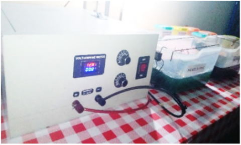
Figure 2. The electroplating process is carried out in the laboratory
2.1 Treatment method
This study uses the tank plating method, where the experimental process uses a tank as a container containing a metal coating liquid that can soak the substrate as a whole, and is directly supplied with electricity at both poles. The container used must be made of acid and base resistant materials. Glass and plastic are ideal materials for this experiment. The rectifier is the source of electricity that flows electricity to the anode and cathode using cables. Both cables on each pole must be well insulated, they must not touch directly. Electric current flows between the anode and cathode poles through the metal coating liquid. The metal or material sample to be coated must be completely clean, and during the installation process on the electroplating equipment must not be touched directly by hand, so researchers must use appropriate gloves, because otherwise it will leave fingerprints on the substrate.
2.2 Research procedures
The research steps or procedures are as follows: substrate preparation, electroplating solution preparation, pre-treatment data collection process, electroplating process, nickel characterization and coating.
2.2.1 Substrate pre-treatment
The substrate (carbon steel) is cleaned from oil, grease, and organic contaminants using a degreasing solvent, then rinsed using running water. Furthermore, to remove rust, the substrate oxide is dipped in a chloride solution (HCl) with a concentration of HCl: 15% and rinsed using deionized water.
2.2.2 Pre-treatment of electroplating solution
The composition of the electroplating solution consists of nickel sulfate (NiSO₄·6H₂O) as much as 250 g/L as a source of nickel ions, nickel chloride (NiCl₂·6H₂O) as much as 50 g/L as anode and conductivity solvent, boric acid (H₃BO₃) as much as 35 g/L as a pH buffer, process stabilizer, brightener as much as 0.5 g/L as a brightener and surface smoother and deionized water as a solvent sufficiently to the total volume of 1 liter.
2.2.3 Electroplating process
The electroplating process uses time variables (3, 5, and 8 minutes) and current strength (10 A, 30 A, and 50 A). The time and current strength variables function to understand the effect of time and electric current on the thickness of the metal layer. The longer, the more metal ions that stick cause a thicker layer, but if it is too long without temperature and pH control, it causes the layer to be rough or cracked. While the higher the current, the faster the metal ions stick, causing faster coating, but if the current is too high, it causes the ions to burn, resulting in coating defects.
2.2.4 Characterization
To evaluate the quality, thickness, strength, and structure of the metal layer that has been deposited on the surface of the base metal. Characterization is done by measuring the weight gain, macro photography for macro surface observation, Scanning Electron Microscope (SEM)-Energy Dispersive X-ray Spectroscopy (EDS) for micro surface observation, and knowing the distribution of nickel ions on the surface of the coated substrate. Furthermore, to determine the effect of electroplating on increasing hardness, a hardness test is carried out on the substrate.
3.1 Substrate (carbon steel) after electroplating
The research results were obtained through a testing process by electroplating on a substrate with various specified variables, namely current strength variables of 10 A, 30 A, and 50 A, and time variables of 3 minutes, 5 minutes, and 8 minutes.
3.1.1 Macro photography
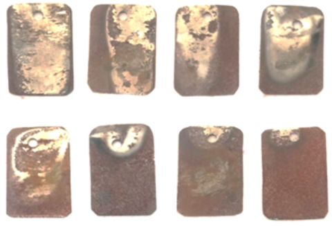
The results of electroplating treatment on the substrate with a current strength of 50 A are shown in Figure 3. It can be seen that the surface of the substrate coated with a time variable of 3 minutes, 5 minutes, and 8 minutes, is not coated properly because some of the layers experience thermal degradation. This is because the ions that migrate from the anode to the cathode are also burned, so it looks charred.
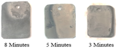
In Figure 4, the electroplating process is carried out using a current of 30 A, with a time variable of 3 minutes, 5 minutes, and 8 minutes. The coating results are seen in the 8-minute treatment, most of the layers experience thermal degradation, in the 3-minute treatment, a small part experiences thermal degradation, and in the 3-minute treatment, most are well coated. This happens because the current of 30 A with the research variables is still not appropriate, the electric current is still too large, which causes the coating ions to burn.
Figure 3. Macro photo of the substrate surface that has been electroplated with a current of 50 A
Figure 4. Macro photo of the substrate surface that has been electroplated with a current of 30 A
Figure 5. Macro photo of the substrate surface that has been electroplated with a current of 10 A
The results of electroplating treatment with an electric current of 10 A are shown in Figure 5. The visible results are well coated, only at the time variables of 8 minutes and 5 minutes. There is a small portion of the layer that experiences thermal degradation, but most of it is well and evenly coated. The best results are shown at the time variable of 3 minutes, the surface of the material is evenly coated, and there is no burnt layer.
3.1.2 Weight measurement
The substrate that has been electroplated is then measured for its weight gain. In this measurement, the focus is on the substrate that was electroplated with a treatment time variable of 3 minutes and 5 minutes, because at that time variable the coating works well. The equation used is as follows:
$\Delta m=m_2-m_1$ (1)
Dimana:
$m_1= initial \,\,mass ; m_2= final \,\,mass$
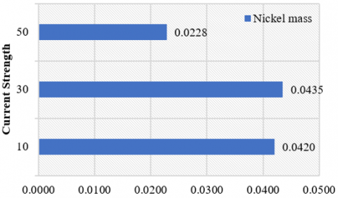
The coated substrates have different weights as shown in Figure 6. This is because the difference in current strength determines the quality of the substrate coating. In coating with a current strength of 10 A, the nickel mass is 0.0420 g, at a current strength of 30 A, the nickel mass is 0.0435 g, and at a current strength of 50 A, the nickel mass is 0.0228 g. At a current strength of 30 A, the weight gain is not ideal as Faraday's law theory because the deposition is too fast so that some nickel ions do not stick properly, while at a current strength of 50 A the nickel mass is smaller than at a current strength of 10 A and 30 A, some layers experience thermal degradation.
Figure 6. Comparison graph of layer thickness and mass increase in 5-minute treatment
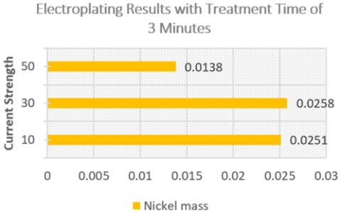
Figure 7. Comparison graph of layer thickness and mass increase at 3-minute treatment
Figure 7 presents the data of electroplating treatment results with a treatment time of 3 minutes. Based on the data in the graph, it is known that the layer with a current strength of 10 A, the nickel mass is 0.0251 g, then the next treatment with a current strength of 30 obtained a nickel mass of 0.0258 g, and at a current strength of 50 A the nickel mass weighs 0.0138 g, as explained in Figure 6. A similar thing also occurs, namely at a current strength of 30 A, the weight gain is not ideal as per Faraday's law theory because the deposition is too fast so that some nickel ions do not stick properly, while at a current strength of 50 A the nickel mass is smaller than at current strengths of 10 A and 30 A, some layers experience thermal degradation.
To determine the layer thickness, it is calculated using the following equation:
$T(\mu m)=\frac{\Delta m}{\rho . A}$ (2)
Dimana:
$\Delta m=mass \,\,of \,\,nickel ;$
$\rho=$density of nickel
$A=$surface area
$T=\frac{0.0171}{8.908 \times 2}=\frac{0.0420}{17.816}=0.002357 \mathrm{~cm}=25.57 \,\, \mu \mathrm{m}$
$T=\frac{0.0178}{8.908 \times 2}=\frac{0.0435}{17.816}=0.002442 \mathrm{~cm}=24.42 \,\, \mu \mathrm{m}$
$T=\frac{0.0119}{8.908 \times 2}=\frac{0.0228}{17.816}=0.00128 \mathrm{~cm}=12.80 \,\, \mu \mathrm{m}$
The thickness of the layer is calculated using the following equation:
$T=\frac{0.0251}{8.908 \times 2}=\frac{0.0251}{17.816}=0.001409 \mathrm{~cm}=14.09 \,\, \mu \mathrm{m}$
$T=\frac{0.0258}{8.908 \times 2}=\frac{0.0258}{17.816}=0.001448 \mathrm{~cm}=14.48 \,\, \mu \mathrm{m}$
$T=\frac{0.0138}{8.908 \times 2}=\frac{0.0138}{17.816}=0.000774 \mathrm{~cm}=7.74 \,\, \mu \mathrm{m}$
3.1.3 SEM-EDS microstructure analysis
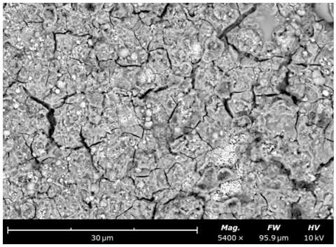
To analyze the microstructure of the coating on the substrate, SEM-EDS tests were carried out on the successfully coated substrates and the thermally degraded defective ones. The substrate surface in Figure 8 is the result of coating with a current strength of 10 A, looks well coated, and the surface is relatively dense with a granular structure. The surface image shows that nickel deposition on the substrate takes place homogeneously, where Ni²⁺ ions are reduced and form nickel crystals. This shows that the electroplating process parameters, especially the current strength and coating time, are within safe limits.
The results of EDS analysis are presented in Figure 9. Nickel (Ni) element was detected as the main component with the highest peak intensity, indicating that the substrate surface is dominated by nickel metal from the electroplating process. In addition, iron (Fe) element was also detected, which came from the carbon steel substrate, but with a much lower intensity, indicating that the nickel layer has successfully covered most of the surface. Oxygen (O), carbon (C), and sulfur (S) elements also appear in small amounts, which come from environmental contamination, residual electroplating solutions. Nickel plating through electroplating successfully forms an effective layer on the substrate surface (carbon steel).
Figure 8. SEM photo results of a well-coated substrate
Figure 9. EDS test result spectrum of a well-coated substrate
Figure 10. SEM photo results of the substrate whose layer has been thermally degraded
Figure 10 is the result of plating with a current strength of 50 A. The surface of the substrate that experienced thermal degradation and the SEM photo results show irregularities and morphological defects indicating uncontrolled nickel crystal growth due to excessive deposition caused by excessive plating current. This condition causes Ni atoms to not be able to be arranged tightly, where nickel crystals grow with a dendritic structure indicating over-potential plating.
The results of the EDS analysis in Figure 11 show that in the layer that has undergone thermal degradation, the oxygen (O) content appears high, this is due to the electroplating current being too high causing the Ni²⁺ ion reduction reaction to occur too quickly and unstable so that local heating occurs on the substrate surface. The deposited nickel is oxidized to NiO due to local heating and contact with the remaining oxygen in the water solution.
Figure 11. EDS test result spectrum of thermally degraded substrate
3.1.4 Microhardness test
In this study, the quality of the electroplating treatment results was tested with micro hardness. The addition of material hardness is obtained from the coating metal, which has a fine-grain microstructure with a grain boundary strengthening mechanism, and also the compressive stress that occurs in the electroplating process, so that the material hardness increases.
Substrate hardness test using the Vickers microhardness method, in measurements using a small pyramid-shaped indenter, the test results of each material are shown in Figure 12. Namely, the material with 3-minute treatment has a hardness value of 80.95 HV, the material with 5-minute treatment has a hardness value of 138.333 HV, and the material with 8-minute treatment has a hardness value of 167.025 HV. The highest hardness test value is found in the 8-minute treatment. This occurs because during the electroplating process, the electrolyte settles on the surface of the material, where plastic deformation occurs due to the interaction between metals. This causes compressive stress or tensile stress, which causes the material's hardness value to increase.
Figure 12. Comparison chart of substrate hardness values
The longer the electroplating time, the more Ni²⁺ ions are reduced, the thicker the nickel layer, causing the growth of nickel crystals to be more uniform and denser, thereby increasing hardness. In addition, residual stress caused by rapid deposition increases surface hardness.
Nickel is a metal that has a fairly high hardness and is resistant to abrasion and corrosion. When nickel is coated on the surface of the substrate (carbon steel) it causes an increase in the total hardness of the substrate surface. During electroplating, nickel ions (Ni²⁺) are reduced to nickel metal (Ni⁰) at the cathode (substrate surface):
Cathode: $\mathrm{Ni}^{2+}+2^{e-} \rightarrow {Ni}(solid )$
3.1.5 Immersion test
The purpose of electroplating treatment is to protect the material from corrosion. Therefore, the coated material is given corrosion treatment to determine the ability of the coating to protect the material from corrosion. Corrosion testing is carried out using the immersion method, referring to ASTM G31 - Standard Guide for Laboratory Immersion Corrosion Testing of Metals and ASTM G1 - Standard Practice for Preparing, Cleaning, and Evaluating Corrosion Test Specimens [22].
The test was conducted using a well-coated and defective substrate, immersed in a container filled with water. The test results are presented in Figure 13, where the material with a defective layer is attacked by corrosion in that part. The defective layer occurs because the layer experiences thermal degradation due to the electric current used during the electroplating treatment being too large. In Figure 13, it is clearly seen that the part of the substrate that is well coated with nickel does not experience corrosion, while in the part that experiences thermal degradation, the substrate is not protected, so that direct interaction with the corrosive environment causes corrosion.
Figure 13. Photos of corroded material
The research on electroplating process using nickel on carbon steel substrate produces nickel layer on the surface that serves to protect the substrate, where the quality of the layer is influenced by the process parameters, especially the current strength and the duration of the coating. The results of macro photography, SEM, weight measurement, EDS analysis, micro hardness test, and corrosion test, found that the optimum condition was obtained at a current strength of 10 A and a coating time of 3-5 minutes, where the surface was evenly coated, free from thermal defects, and showed a stable increase in mass and thickness. While the hardness value tends to increase with the longer the coating time, because the thicker the layer, the higher the residual stress, which causes it to be harder. The highest hardness was achieved at 8 minutes of treatment, which was 167.025 HV. However, the substrate with an 8 minutes treatment time experienced thermal degradation, resulting in a defective layer. This caused a decrease in wear and corrosion resistance. This increase in hardness must be balanced with good morphological quality to prevent structural defects. Corrosion testing proved that a flat and homogeneous nickel layer effectively protects the substrate from corrosive environments, while a layer that was defective due to thermal degradation proved to fail to provide protection, causing direct corrosion to the carbon steel substrate.
This research can be carried out through the Regular Fundamental Research (PFR) scheme, which is a research program organized and funded by the Directorate of Research, Technology, and Community Service (DRTPM) under the Ministry of Higher Education, Culture, Research and Technology of the Republic of Indonesia (KEMDIKBUDRISTEK). Through this research article, the research team expresses much gratitude and appreciation for the opportunity given.
|
T |
thickness |
|
∆m |
mass of nickel |
|
m1 |
initial mass |
|
m2 |
final mass |
|
ρ |
type mass |
|
A |
surface area |
|
Ni2⁺ |
nickel ion |
|
Nio |
nickel metal |
[1] Liu, J., Fang, X., Zhu, C., Xing, X., Cui, G., Li, Z. (2020). Fabrication of superhydrophobic coatings for corrosion protection by electrodeposition: A comprehensive review. Colloids and Surfaces A: Physicochemical and Engineering Aspects, 607: 125498. https://doi.org/10.1016/j.colsurfa.2020.125498
[2] Jayakrishnan, D.S. (2012). Electrodeposition: The versatile technique for nanomaterials. In Corrosion Protection and Control Using Nanomaterials, Woodhead Publishing, pp. 86-125. https://doi.org/10.1533/9780857095800.1.86
[3] Zhong, Z., Lin, G., Hu, T., Wang, Z., Wang, S., Xia, H., Zhang, L. (2025). A review of external field-enhanced metal electrodeposition: Mechanism and applications. JOM, 77(2): 665-685. https://doi.org/10.1007/s11837-024-06968-7
[4] Kumaraswamy, J., Kumar, V., Purushotham, G. (2021). A review on mechanical and wear properties of ASTM a 494 M grade nickel-based alloy metal matrix composites. Materials Today: Proceedings, 37: 2027-2032. https://doi.org/10.1016/j.matpr.2020.07.499
[5] Loto, C.A. (2016). Electroless nickel plating–A review. Silicon, 8: 177-186. https://doi.org/10.1007/s12633-015-9367-7
[6] Li, G., Jiang, W., Guan, F., Zhu, J., Zhang, Z., Fan, Z. (2021). Microstructure, mechanical properties and corrosion resistance of A356 aluminum/AZ91D magnesium bimetal prepared by a compound casting combined with a novel Ni-Cu composite interlayer. Journal of Materials Processing Technology, 288: 116874. https://doi.org/10.1016/j.jmatprotec.2020.116874
[7] Cui, Z., Li, X., Bai, X., Ren, X., Ou, X. (2023). A comprehensive review of foreign-ion doping and recent achievements for nickel-rich cathode materials. Energy Storage Materials, 57: 14-43. https://doi.org/10.1016/j.ensm.2023.02.003
[8] Hou, P., Yin, J., Ding, M., Huang, J., Xu, X. (2017). Surface/interfacial structure and chemistry of high-energy nickel-rich layered oxide cathodes: Advances and perspectives. Small, 13(45): 1701802. https://doi.org/10.1002/smll.201701802
[9] Mahidashti, Z., Aliofkhazraei, M., Lotfi, N. (2018). Review of nickel-based electrodeposited tribo-coatings. Transactions of the Indian Institute of Metals, 71: 257-295. https://doi.org/10.1007/s12666-017-1175-x
[10] Kim, Y., Seong, W.M., Manthiram, A. (2021). Cobalt-free, high-nickel layered oxide cathodes for lithium-ion batteries: Progress, challenges, and perspectives. Energy Storage Materials, 34: 250-259. https://doi.org/10.1016/j.ensm.2020.09.020
[11] Lahiri, A.K. (2017). Applied Metallurgy and Corrosion Control. Springer, Singapore. https://doi.org/10.1007/978-981-10-4684-1
[12] Qian, Y., Li, Y., Jungwirth, S., Seely, N., Fang, Y., Shi, X. (2015). The application of anti-corrosion coating for preserving the value of equipment asset in chloride-laden environments: A review. International Journal of Electrochemical Science, 10(12): 10756-10780. https://doi.org/10.1016/S1452-3981(23)11298-3
[13] Okokpujie, I.P., Tartibu, L.K., Musa-Basheer, H.O., Adeoye, A.O.M. (2024). Effect of coatings on mechanical, corrosion and tribological properties of industrial materials: A comprehensive review. Journal of Bio-and Tribo-Corrosion, 10(1): 2. https://doi.org/10.1007/s40735-023-00805-1
[14] Zhang, P., Liu, Z. (2017). Enhancing surface integrity and corrosion resistance of laser cladded Cr–Ni alloys by hard turning and low plasticity burnishing. Applied Surface Science, 409: 169-178. https://doi.org/10.1016/j.apsusc.2017.03.028
[15] Amanov, A. (2019). Surface engineering-controlled tribological behavior and adhesion strength of Ni-Cr coating sprayed onto carburized AISI 4340 steel substrate. Surface and Coatings Technology, 370: 144-156. https://doi.org/10.1016/j.surfcoat.2019.04.087
[16] Kumar, N., Choubey, V.K. (2024). Recent trends in coating processes on various AISI steel substrates: A review. Journal of Materials Science, 59(2): 395-422. https://doi.org/10.1007/s10853-023-09239-z
[17] Wei, X., Roper, D.K. (2014). Tin sensitization for electroless plating review. Journal of the Electrochemical Society, 161(5): D235. https://doi.org/10.1149/2.047405jes
[18] Giurlani, W., Zangari, G., Gambinossi, F., Passaponti, M., Salvietti, E., Di Benedetto, F., Innocenti, M. (2018). Electroplating for decorative applications: Recent trends in research and development. Coatings, 8(8): 260. https://doi.org/10.3390/coatings8080260
[19] Ma, C., Wang, S.C., Walsh, F.C. (2015). Electrodeposition of nanocrystalline nickel–cobalt binary alloy coatings: A review. Transactions of the IMF, 93(2): 104-112. https://doi.org/10.1179/0020296714Z.000000000218
[20] Setiawan, F., Walikram, D., Sehono, S., Ariebowo, T., Putra, I.R. (2022). Analysis of the effect of time on tensile strength and hardness of electroplating method using nickel on Aluminum 7075. Key Engineering Materials, 935: 17-23. https://doi.org/10.4028/p-5m4r14
[21] Nickel Institute. (2022). Nickel Plating Handbook. https://nickelinstitute.org/media/lxxh1zwr/2023-nickelplatinghandbooka5_printablepdf.pdf.
[22] Malaret, F. (2024). Semi-quantitative categorization method for the corrosion behavior of metals based on immersion test. Metals, 14(4): 409. https://doi.org/10.3390/met14040409