Anwr M. Albaghdadi* | Masri B. Baharom | Shaharin A. Sualiman
© 2021 IIETA. This article is published by IIETA and is licensed under the CC BY 4.0 license (http://creativecommons.org/licenses/by/4.0/).
OPEN ACCESS
In this paper, a new configuration of Crank-Rocker (CR) model has been proposed by duplicating its mechanism. The method has been implemented to overcome vibration problem on a single-piston Crank-Rocker engine caused by system unbalance. The new method suggests combining conventional method of adding counterweights to reduce shaking forces and eliminating the inertial moments on system by implementing the new layout. A dynamic study of the new model is presented, then the objective function is derived and implemented to perform the optimization process. Related design variables and system constraints are introduced to determine attached counterweights optimized characteristics. For results validation, the simulation, dynamic analysis, and optimization process were conducted using ADAMS VIEW® software. The output results were presented and discussed to verify the validity of the suggested method. It was noticed that the method was very effective and has managed to reduce the total shaking forces by about 91%, shaking moment by about 66%; and the driving torque by 27%.
Crank-Rocker (CR) engine, Double Crank-Rocker (DCR), engine vibration, four-bar mechanism, balancing
Crank-Rocker (CR) mechanisms can be found in many applications due to their simple design, wide functionality, and ease of production. Many researches have introduced different approaches to study the kinematics and dynamic synthesis of this mechanism that can be used as a base for further related studies [1-3].
Previous studies led to the invention of a new single piston engine called Crank Rocker (CR) engine by a research team at Centre for Automotive Research and Electric Mobility (CAREM), Universiti Teknologi Petronas (UTP) Malaysia [4]. Since then, the CR engine is under continuous investigation to achieve the most beneficial outcome from such design [4-9]. Although single piston design showed promising results in term of efficiency and indicated power, noticeable high vibrations during operation of the engine was noticed mainly due to the unbalance of engine. The current CR engine architecture requires further development owing to its oscillating mechanism. Fluctuating forces and moments are acting during CR engine operation which lead to unbalance and shaking of the engine, affecting its mechanical performance. For applications where the crank speed is high, a dynamic balancing to reduce shaking forces and shaking moments are required. Ultimate dynamic balancing of a CR mechanism is considered a challenge because it is a trade-off between balancing forces and moments [10].
In this research, our aim is to introduce a new engine layout that can be used to overcome vibrations resulted from a single cylinder CR engine. Therefore, a double-piston crank rocker (DCR) configuration is suggested in this research to achieve satisfactory balancing results. Although many techniques can be devoted to studying the dynamic balancing of four-bar linkages, few researches have been introduced in duplicating this mechanism and studying its effect on balancing [11, 12]. Therefore, it is attempting to study the DCR system balancing, where a combination between complete shaking force elimination using counterweights and mechanism duplication for shaking moment reduction are presented and discussed.
In his paper, Arakelian [12] introduced a solution for the problem of shaking moment exerted on double crank-slider mechanism. Similarly, van der Wijk et al. [13] introduced a systematic study of the dynamic behaviour of a single-crank doble-slider mechanism to investigate the possibility of balancing such system.
Basically, it can be noticed that several researchers have focused on developing certain methods for practical mechanism balancing. Some of these methods include adding counterweights, distributing linkages’ masses, while others use rotating disks or duplicating linkages [12, 14-19]. Mohammed et al. [20] presented a method for complete shaking force elimination of a crank-rocker mechanism by using counterweights. His method was simple to grasp and practical, where the first step involves adding counterweights to the crank and rocker links and then followed by applying the law of motion to obtain the balanced case. However, Xi and Sinatra [21] stated that adding counterweights to eliminate the shaking forces increased the moment of inertia of the mechanism, leading to the increase in the shaking moments and vibration. In addition, Kochev [11] conducted a review on methods for balancing of a four-bar mechanism and concluded that a total balanced mechanism could be achieved on the price of complexity and mass increase.
In previous studies, scholars tried to formulate and develop mathematical equations for the dynamic problem and find a suitable solution for these equations using different mathematical and programming approaches [22-25]. Demeulenaere et al. [26] in their research indicated that dynamic reactions of four-bar mechanism can be reduced by adding counterweights. He dealt with this problem as an optimization problem, which could be solved as a convex problem to find the optimum solution. Chaudhary and Saha [27] pointed some difficulties of the four-bar linkage balancing problem such as formulating the dynamic problem, the objective function and the system constraints. Therefore, the author proposed dynamic equations using maximum recursive algorithm to accomplish the optimum balancing of the four-bar mechanism.
In this paper, a dynamic analysis for the crank-rocker mechanism is initially illustrated. Then the adopted optimization method for both shaking forces and moment balancing is introduced. Lastly, a DCR design approach, simulation and analysis is validated using ADAMS VIEW® software.
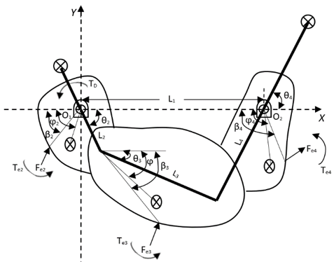
In this section, a dynamic analysis considering the addition of balancing counterweights to the four-bar mechanism is introduced [10, 28]. Then, a mathematical model for the DCR mechanism is derived based on basic analysis for design purposes. Figure 1a shows basic configuration of a standard four-bar mechanism, and Figure 1b illustrates free body diagram of this mechanism under different dynamic forces.
(a)
(b)
Figure 1. Four bar mechanism: (a) Dynamic load Representation; (b) Free body diagram
From Figure 1a above, this mechanism arrangement has links of length Li, (where i=1 to 4). Each link has a mass, mi and moment of inertia, Ii. The mechanism rotates with angular velocity, ωi and angular acceleration, ai. The transitional velocity vi and transitional acceleration, ai are both vectors originating from each link center of gravity. External forces and torques exerted on the ith length are donated by Fei and Tei respectively, while TD is the crank driving torque.
Based on the free body diagram shown in Figure 1b, we can use the following equations to find the reaction forces on the coupling link joints A and B as follows [10]:
$F_{23 x}=\frac{\left(R v_{B x}+S v_{B y}-P\right) v_{A y}-Q v_{B y}}{V}$ (1)
$F_{23 y}=\frac{\left(-R v_{B x}-S v_{B y}+P\right) v_{A x}-Q v_{B x}}{V}$ (2)
$F_{43 x}=\frac{\left(P-S v_{B y}\right) v_{A y}-\left(R v_{B x}-Q\right) v_{B y}}{V}$ (3)
$F_{43 y}=\frac{\left(R v_{B x}-P\right) v_{A y}+\left(S v_{B y}-Q\right) v_{A x}}{V}$ (4)
where:
$R=m_{3} a_{3 x}-F_{e 3 x}$ (5)
$S=m_{3} a_{3 y}-F_{e 3 y}$ (6)
$V=v_{B x} v_{A y}-v_{B y} v_{a x}$ (7)
in which, $F_{i j x, y}$ are the pivot reaction forces in x and y components by the ith link on the jth link (i, j = 1-4). Similarly, $F_{e i x, y}$ are the external forces in x and y components applied on each link. $v_{A x, y}$, $v_{B x, y}$ are velocity components of both point A and B, respectively. $a_{i x, y}$ is the acceleration component of centre of gravity of each link.
$P=\sum_{i=2}^{3} K_{i}-T_{D} \omega_{2}$ (8)
$Q=\sum_{i=3}^{4} K_{i}$ (9)
TD and Ki can be found from the virtual work applied on a system in which:
$T_{D}=\sum_{i=2}^{4} \frac{K_{i}}{\omega_{2}}$ (10)
where:
$K_{i}=m_{i} a_{i} \mathrm{v}_{i}-T_{e i} \omega_{i}-F_{e i} \mathrm{v}_{e i}+I_{i} \alpha_{i} \omega_{i}$ (11)
As a result of solving Eqns. (1)-(4), ground joints reaction forces can be obtained as follows:
$F_{12 x}=F_{23 x}+m_{2} a_{2 x}-F_{e 2 x}$ (12)
$F_{12 y}=F_{23 y}+m_{2} a_{2 y}-F_{e 2 y}$ (13)
$F_{12 y}=F_{23 y}+m_{2} a_{2 y}-F_{e 2 y}$ (14)
$F_{14 y}=F_{43 y}+m_{4} a_{4 y}-F_{e 4 y}$ (15)
And we can write the total shaking force component Fsxand Fsy as:
$F_{s x}=-\left(F_{12 x}+F_{14 x}\right)$ (16)
$F_{s y}=-\left(F_{12 y}+F_{14 y}\right)$ (17)
Since all free body diagram forces are calculated, it can be noticed that shaking forces are vector sums of the transitional inertia moments. Also, the shaking moments are the vector sum of the mass inertia moments and moments of applied forces [24, 29]. Hence, the total inertial force can be written as:
$\sum_{i=2}^{4} F=F_{12}+F_{14}=0$ (18)
Similarly, for the total system moment MO1 about crank pivot O1 is formulated as:
$\sum M_{01}=-\sum_{i=2}^{4} R_{G i} m_{i} a_{i}-\sum_{i=2}^{4} I_{i} \alpha_{i}-\sum_{i=2}^{4} T_{e i}-\sum_{i=2}^{4} F_{e i} h_{i}+M_{12}=0$ (19)
Under balanced condition, this equation can be expressed as:
$M_{12}=\sum_{i=2}^{4} R_{G i} m_{i} a_{i}+\sum_{i=2}^{4} I_{i} \alpha_{i}+\sum_{i=2}^{4} T_{e i}+\sum_{i=2}^{4} F_{e i} h_{i}$ (20)
where, M12 is the reaction moment about pivot O1, $R_{G i}$ is the distance from center mass of gravity of each link to the crank joint at pivot O1, and hi is the distance from the external forces applied on links to the crank joint at pivot O1.
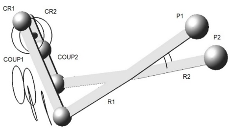
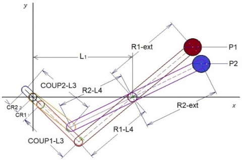
Figure 2 below shows the initial DCR illustration with rocker extension and piston that resembles the CR engine configuration. The main component of this mechanism are the crank links (CR1 and CR2), coupler links (COUP1 and COUP2) and the rocker links (R1 and R2). All forces and moments are designated to relevant corresponding link, also force components are represented in the x-y coordinates system.
(a)
(b)
Figure 2. DCR mechanism: (a) 3-D view with mechanism motion path; (b) Schematic side view
Eqns. (18)-(20) represent the shaking forces and shaking moments of a single four-bar mechanism. Prior to implementing these equations to formulate a double mechanism model, few assumptions were made for simplification purposes. First, for a system where the ground pivots are collinear, the effect of all x-axis force components on reaction moment are zero, therefore only the y-axis force components and inertial mass moments are in effect. In addition, since this approach is based on planar analysis and for calculation simplification, the distance between the two crank-pivots and rocker-pivots is not considered in moment calculations. This is because they are having insignificant affect when implemented compared to their value when consider the distance L1 in moment calculations. Another assumption, since symmetry is preferred for such arrangement, rocker extension and crank counterweight links are set to have equal lengths as the crank and rocker links, respectively.
In Eq. (10), the driving torque value is affected by rotation speed change, hence input speed need to be fixed to a desirable level to prevent any complication by adding a control system to the working mechanism [11, 30]. Therefore, the engine is assumed to rotate with constant angular velocity and having a rigid body. Considering these assumptions and upon applying dynamic theories on this system, we can rewrite the reaction force equations as follows:
$F_{C R x}=-\left(F_{C R 1 x}+F_{C R 2 x}\right)$ (21)
$F_{C R y}=-\left(F_{C R 1 y}+F_{C R 2 y}\right)$ (22)
$F_{R x}=-\left(F_{R 1 x}+F_{R 2 x}\right)$ (23)
$F_{R y}=-\left(F_{R 1 y}+F_{R 2 y}\right)$ (24)
where, $F_{C R x, y}$ are the sum of force components at the crank joints, and $F_{R x, y}$ are the sum of force components at the rocker joints.
For the total shaking force $F_{t}$ and its components $F_{S x, y}$, the equations can be written as:
$F_{S x}=F_{C R x}+F_{R x}$ (25)
$F_{S y}=F_{C R y}+F_{R y}$ (26)
$F_{t}=F_{S x}+F_{S y}$ (27)
Similarly, the crank shaking moment $M_{C R}$ equation about crank pivot can be formulated as:
$\begin{aligned} M_{C R}=-\left(F_{R 1 y}+\right.& \left.F_{R 2 y}\right) L_{1} \\ &-\left(I_{C O U P 1} \alpha_{C O U P 1}+I_{C O U P 2} \alpha_{C O U P 2}\right.\\ & \left.+I_{R 1} \alpha_{R 1}+I_{R 2} \alpha_{R 2}\right)-T_{D} \end{aligned}$ (28)
Also, rocker shaking moment MR about rocker pivot becomes:
$M_{R}=F_{C R y} L_{1}-\left(I_{C O U P 1} \alpha_{C O U P 1}+I_{C O U P 2} \alpha_{C O U P 2}\right.$
$\left.+I_{R 1} \alpha_{R 1}+I_{R 2} \alpha_{R 2}\right)$ (29)
where, I and α are the moment of inertia and angular acceleration of corresponding link, respectively. For the case of fixed crank angular velocity, the angular acceleration of crank linkage is zero, and this eliminates the crank inertial moment effect. To achieve system balancing in term of shaking moments we follow:
$M_{t}=M_{R}-M_{C R}=0$ (30)
$M_{t}=F_{C R y} L_{1}+\left(F_{R 1 y}+F_{R 2 y}\right) L_{1}+T_{D}$ (31)
Adding the shaking moment from (27) and (28) lead into a minimum value of resultant moment Mt, since moments resulted from forces or moment of inertia tends to cancel each other due to the change in direction, see Figure 3.
Normalized shaking forces and moments are introduced for better results visualization, these values can be formulated as follows [31]:
$F^{o}=\frac{F}{m_{2} L_{2} \omega_{2}^{2}}$ (32)
$M^{o}=\frac{M}{m_{2} L_{2}^{2} \omega_{2}^{2}}$ (33)
$T^{o}=\frac{T}{m_{2} L_{2}^{2} \omega_{2}^{2}}$ (34)
where, $F^{o}$, $M^{o}$, and $T^{o}$ are the normalized values of acting force F, moment M and torque T respectively.
In this section, the optimization criteria for balancing of the DCR mechanism is introduced. Three factors are selected to perform the optimization process which are determining the objective function, assigning the design variables, and identifying system constraints.
In the previous section, parameters that have impacts on the DCR mechanism such as links basic geometry and inertial moments were formulated. To overcome the vibration on this system, adding and optimizing counterweight masses of the system is performed, in such way that forces on the system tend to cancel each other’s effect. However, increasing mechanism total mass would lead to the increase in the body inertial moments and multiply system shaking moments which is not desirable. Here comes the role of duplicating the mechanism, where opposed momentums exert and cancel each other’s effects on both sides.
For this reason, our aim during performing this optimization is to vary and determine the counterweight masses and location which will lead to the reduction in shaking forces in y-direction, also to minimize the total driving torque to maintain acceptable level of shaking moment. From Eqns. (27) and (31), the objective function can be written as:
minimize $f(X)=\sigma_{1} F_{t}+\sigma_{2} M_{t}$ (35)
where, σ is weighting factor. In this study three cases of weighting factor ($\sigma_{1}, \sigma_{2}$) arbitrary values are considered for testing trade-off impact of shaking forces and moments on optimization process. For case-1 (0.5,0.5), case-2 (0.7,0.3) and case-3 (0.3, 0,7). The design variable X identified by:
$X=\left\{C W_{j}, P_{j}\right\}$ (36)
where, $C W_{j}$ are counterweight masses added on link (i), (j=1 to 4) and Pj is the position distance of each counterweights $C W_{j}$ along the corresponding link (i) measured from coupler joint. The optimization is performed under constraints of crank rotation angle θ2 from 0° to 360° with constant angular velocity ω2 and specific rocker stroke determined by rocker extension link length $L_{4}$, and oscillating angle θ4 (Figure. 2). These constraints were for achieving effective kinetic synthesis of the system and to prevent non-feasible solutions when performing dynamic optimization of this system. The model parameters have the characteristics and properties mentioned in Table 1 which was introduced using optimization method in Ref. [32]. Moreover, Figure 2(a) introduces this mechanism kinematic behaviour presented by linkages path motion.
Table 1. DCR links dimensions and mass properties
|
Link |
Length (mm) |
Mass (kg) |
Moment of Inertia [IXX, IYY, IZZ ], (kg.mm2) |
|
CR1, CR2 |
141.4 |
1.075 |
[2.8 $\times 10^{3}$, 2.7 $\times 10^{3}$, 172.4] |
|
R1, R2 |
690.8 |
4.391 |
[1.9 $\times 10^{5}$, 1.9 $\times 10^{5}$, 743.9] |
|
COUP1, COUP2 |
282.8 |
1.958 |
[1.64 $\times 10^{4}$, 1.6 $\times 10^{4}$, 319.5] |
|
L1 |
481.0 |
NA |
NA |
In this section, validation and implementation of the earlier dynamic and optimization approach of DCR mechanism is illustrated.
This system assumed to be running under fixed angular velocity of 2000 rpm, where no external forces or torques were applied. Four counterweights with arbitrary masses and arbitrary positions are placed on the four crank and rocker linkages, as shown in Figure 3. The optimization and dynamic simulation were performed using ADAMS VIEW® software. The objective function stated in (35) was implemented to optimize this system with three cases, (i.e., case-1, case-2, and case-3) where weighting factors varied as explained in section 3. Figure 4 shows objective function versus iteration for the three cases. Table 2 represents the initial, boundary limits and optimized values for counterweights.
Table 2. Counterweights parametric values prior and after optimization
|
Design Variables |
Initial condition |
Lower limit |
Upper limit |
Optimized Value |
||
|
Case 1 (0.5, 0.5) |
Case 2 (0.7, 0.3) |
Case 3 (0.3, 0.7) |
||||
|
CW1 (kg) |
3 |
0.01 |
20 |
0.010 |
0.010 |
0.010 |
|
P1 (mm) |
142 |
0 |
142 |
97.94 |
130.26 |
83.033 |
|
CW2 (kg) |
3 |
0.01 |
20 |
0.119 |
0.042 |
0.511 |
|
P2 (mm) |
142 |
0 |
142 |
94.654 |
118.96 |
77.569 |
|
CW3 (kg) |
3 |
0.01 |
20 |
4.129 |
4.049 |
4.251 |
|
P3 (mm) |
0 |
0 |
700 |
0.000 |
0.000 |
0.0138 |
|
CW4 (kg) |
3 |
0.01 |
20 |
3.648 |
3.489 |
3.838 |
|
P4 (mm) |
0 |
0 |
700 |
0.000 |
0.000 |
0.082 |
Figure 3. DCR moments action principle
Figure 4. Objective Function Vs Iteration: (a) Case1, (b) Case2 and (c) Case3
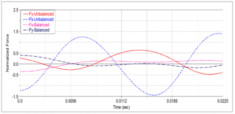
Figure 5. Unbalanced and balanced results for case-1 for (a) Normalized shaking forces, (b) Normalized shaking moment and (c) Normalized Driving torque
For the three cases considered in this study, Figures 5, 6, and 7 introduce plot graphs for unbalanced and balanced values of normalized shaking forces, shaking moments and driving torque. Normalized values were obtained using Eqns. (32)-(34).
Figure 5 represents case-1, and it can be noticed that optimized results were better when compared to the original unbalanced mechanism. RMS results shows that shaking forces were reduced by a value of 90.51%, shaking moments were reduced by a value of 66.67% and driving torque was reduced by 26.97%.
Similarly, Figure 6 represents case-2, resulted RMS for shaking forces were reduced by 91.64%, shaking moments were reduced by 65.74% and driving torque was reduced by 27.39%. were reduced by 65.74% and driving torque was reduced by 27.39%.
Figure 7 represents case-3, the results for shaking forces reduction, shaking moment reduction and driving torque reduction are 88.19%, 65.74%, and 25.31% respectively. It can be noticed that case-2, ($\sigma_{1}, \sigma_{2}$) values (0.7, 0.3), gives best results in term of reducing shaking forces and driving torque, while all cases giving close results in term of reducing shaking moments.
Figure 6. Unbalanced and balanced results for case-2 for (a) Normalized shaking forces, (b) Normalized shaking moment and (c) Normalized Driving torque
Figure 7. Unbalanced and balanced results for case-3 for (a) Normalized shaking forces, (b) Normalized shaking moment and (c) Normalized Driving torque
Table 3. Dynamic behaviour resulted by different optimization methods, a comparison
|
|
Reference Mechanism |
Yan |
FFB |
Bram |
This study |
|||
|
Case 1 (0.5, 0.5) |
Case 2 (0.7, 0.3) |
Case 3 (0.3, 0.7) |
||||||
|
Ft |
Max |
7300 |
1264.42 |
655.78 |
1558.4 |
724.66 |
670.14 |
913.47 |
|
Min |
-6422.48 |
-404.57 |
-32.87 |
-1226.6 |
-306.25 |
-110.38 |
-581.99 |
|
|
Ave. |
527.92 |
463.6 |
268.3 |
460.2 |
287.61 |
284.86 |
290.86 |
|
|
RMS |
4722 |
820.2 |
380.6 |
996.5 |
448 |
394.8 |
557.9 |
|
|
RMS reduction % |
82.63 |
91.94 |
78.9 |
90.51 |
91.64 |
88.19 |
||
|
Mt×106 |
Max |
2.06 |
2.34 |
0.85 |
1.43 |
0.67 |
0.73 |
0.63 |
|
Min |
-1.54 |
-1.27 |
-0.41 |
-0.91 |
-0.38 |
-0.38 |
-0.4 |
|
|
Ave. |
0.24 |
-0.17 |
0.54 |
0.89 |
0.95 |
0.83 |
0.11 |
|
|
RMS |
1.08 |
1.15 |
0.42 |
0.73 |
0.36 |
0.37 |
0.37 |
|
|
RMS reduction % |
-6.48 |
61.11 |
32.41 |
66.67 |
65.74 |
65.74 |
||
|
Td×106 |
Max |
3.65 |
1.98 |
2.61 |
2.13 |
2.66 |
2.63 |
2.7 |
|
Min |
-3.19 |
-1.71 |
-2.27 |
-1.85 |
-2.32 |
-2.29 |
-2.35 |
|
|
Ave. |
0.72 |
0.73 |
0.52 |
0.42 |
0.53 |
0.52 |
0.53 |
|
|
RMS |
2.41 |
1.31 |
1.73 |
1.42 |
1.76 |
1.75 |
1.8 |
|
|
RMS reduction % |
45.64 |
28.22 |
41.08 |
26.97 |
27.39 |
25.31 |
||
Moreover, Table 3 introduced a comparison between the three cases introduced in this study, full force balance method (FFB) in the paper [20], optimization methods by Yan et al. [10], and Demeulenaere et al. [26]. It can be noticed that FFB and case-2 of this study give best results in term of shaking force reduction by about 91%. For shaking moment reduction, the three cases of this study introduced best results by about 66% then comes FFB with about 61%.
For driving torque reduction, results from the paper [10, 26] introduce best results by about 45% and 41% respectively, while this study introduces about 25 to 27% reduction in driving torque values.
For better understanding of forces and moments cancellation effect for DCR mechanism that illustrated previously in Figure 3, analysis of force and moment component are illustrated in Figures 8 and 9.
Figure 8. Normalized shaking forces components of DCR mechanism before and after balancing
Figure 8 represents normalized forces values for force component acting on DCR in x- and y- direction. These forces show higher values and asymmetrical behaviour which leads to the presence of higher shaking forces on system. However, these forces show less amplitudes and better symmetrical behaviour that brings total shaking forces into an acceptable value.
Figure 9. Normalized shaking Crank and Rocker moments of DCR mechanism before and after balancing.
Similarly, Figure 9 represents normalized crank and rocker moment values for acting on DCR. These moments show higher values and asymmetrical behaviour which leads to the presence of higher shaking moments on system. On the other hand, these moments show less amplitudes and better symmetrical behaviour that brings shaking moments to cancel each other effect and reduce total shaking moment value.
Even though considering both shaking forces and shaking moments when performing the optimization process is giving better results, but it is also noticed that when applying complete force balance on the DCR system, it can achieve high balancing results. since duplicating the mechanism highly helps in reducing shaking moments and adding the counterweights reduces shaking forces by this system.
In this work, a double crank-rocker (DCR) mechanism was suggested as a new configuration to reduce the vibration resulted from a single CR mechanism. The theory is based on combining counterweights to balance shaking forces and duplicating the working mechanism to overcome the resulted shaking moments. A dynamic study of the four-bar mechanism was introduced, then evolved to satisfy the balancing requirements of the new designed model.
Later, based on the dynamic analysis, the objective function and design variables used in optimization process were formulated. validation of the optimized system showed that adding counterweights to the DCR result in reducing both shaking forces and shaking moments to a satisfying result. However, increment of mechanism weight due to mechanism duplicating, and counterweight addition was increased by about 51%. Further work on different mechanism layout should be done to investigate vibration behaviour due to the implementation of this developed mechanism.
|
a |
transitional Acceleration, mm/s2 |
|
Fe |
External Forces, N |
|
Fsh |
Shaking Forces, N |
|
f |
Objective function |
|
I |
Moment of Inertia, Kg.mm2 |
|
Li |
Length of Link i, mm |
|
mi |
Mass of link i, Kg |
|
MCR |
Crank Joint Moment, N.mm |
|
MR |
Rocker Joint Moment, N.mm |
|
Pj |
Counter-weight j, position along link, mm |
|
RGi |
Distance from centre of mass to fixture, mm |
|
Te |
External Torques, N.mm |
|
TD |
Driving Torque, N.mm |
|
v |
Transitional velocity, mm/s |
|
Greek symbols |
|
|
α |
Angular Acceleration, rad/s2 |
|
β |
Angle between force action line and x-axis, rad |
|
ϕ |
Angle between centre of mass and x-axis, rad |
|
μ |
Angle between link i and counterweight, rad |
|
ρ |
Distance between counter-weight mass and fixed joints, mm |
|
θi |
Angle between ith link and x-axis, rad |
|
ω |
Angular velocity, rad/s |
|
X |
Design Variable |
|
Abbreviations |
|
|
CR |
Crank Rocker |
|
CW |
Counterweight |
|
DCR |
Double Crank Rocker |
[1] Roy, L., Sen, A., Chetia, R.P., Borah, M.J. (2008). Analysis and synthesis of four bar mechanism. International Journal of Theoretical and Applied Mechanics, 3(2): 171-186.
[2] Jaiswal, A., Jawale, H.P. (2018). Synthesis and optimization of four bar mechanism with six design parameters. AIP Conf. Proc., 1943(1): 020014 https://doi.org/10.1063/1.5029590
[3] Jian, S., Xu, G. (2013). The dynamic characteristic analysis of four-bar linkages with joint clearances based on the computer simulation. International Journal of Digital Content Technology and its Applications, 7(7): 1183-1191. https://doi.org/10.4156/jdcta.vol7.issue7.140
[4] Mohammed, S.E., Baharom, M.B., Aziz, A.R.A. (2017). Performance and combustion characteristics of a novel crank-rocker engine. Journal of Mechanical Science and Technology, 31(7): 3563-3571. https://doi.org/10.1007/s12206-017-0643-x
[5] Mohammed, S.E., Baharom, M.B., Aziz, A.R.A. (2014). Comparative analysis of two proposed models of connecting rods for crank-rocker engines using finite element method. MATEC Web of Conferences, 13: 02019. https://doi.org/10.1051/matecconf/20141302019
[6] Hassan, S.E.M. (2018). Development, performance and emission assessment of a single-cylinder air-cooled gasoline Crank-Rocker engine. Universiti Teknologi Petronas.
[7] Kardan, R., Baharom, M.B., Mohammed, S.E., Aziz, A.R.A., Zainal, A.E.Z., Firmansyah, (2018). The effect of engine throttle position on the performance characteristics of a crank-rocker engine fitted with a conventional cylinder head. AIP Conf. Proc., 2035(A): 020001. https://doi.org/10.1063/1.5075549
[8] Mohammed, S.E., Baharom, M.B., Aziz, A.R.A. (2016). Thermodynamic analysis of a single cylinder crank-rocker engine. ARPN Journal of Engineering and Applied Sciences, 11(20): 12239-12246.
[9] Mohammed, S.E., Baharom, M.B., Aziz, A.R.A., Zainal, A.E.Z. (2019). Modelling of combustion characteristics of a single curved-cylinder spark-ignition crank-rocker engine. Energies, 12(17): 3313. https://doi.org/10.3390/en12173313
[10] Yan, H.S., Soong, R.C. (2002). Kinematic and dynamic design of four-bar linkages with variable input speed and external applied loads. Transactions of the Canadian Society for Mechanical Engineering, 26(3): 281-309. https://doi.org/10.1139/tcsme-2002-0016
[11] Kochev, I.S. (2000). General theory of complete shaking moment balancing of planar linkages: A critical review. Mechanism and Machine Theory, 35(11): 1501-1514. https://doi.org/10.1016/S0094-114X(00)00015-X
[12] Arakelian, V.H. (2006). Shaking moment cancellation of self-balanced slider-crank mechanical systems by means of optimum mass redistribution. Mechanics Research Communications, 33(6): 846-850. https://doi.org/10.1016/j.mechrescom.2006.03.003
[13] van der Wijk, V., Demeulenaere, B., Gosselin, C., Herder, J.L. (2012). Comparative analysis for low-mass and low-inertia dynamic balancing of mechanisms. J. Mech. Robot., 4(3): 031008. https://doi.org/10.1115/1.4006744
[14] Berkof, R.S., Lowen, G.G. (1971). Theory of shaking moment optimization of force-balanced four-bar linkages. J. Manuf. Sci. Eng. Trans. ASME, 93(1): 53-60. https://doi.org/10.1115/1.3427917
[15] Berkof, R.S. (1973). Complete force and moment balancing of inline four-bar linkages. Mech. Mach. Theory, 8(3): 397-410. https://doi.org/10.1016/0094-114X(73)90076-1
[16] Arakelian, V.H., Smith, M.R. (1999). Complete shaking force and shaking moment balancing of linkages. Mech. Mach. Theory, 34(8): 1141-1153. https://doi.org/10.1016/S0094-114X(98)00067-6
[17] Arakelian, V.H., Smith, M.R. (2005). Shaking force and shaking moment balancing of mechanisms: A historical review with new examples. J. Mech. Des. Trans. ASME, 127(2): 334-339. https://doi.org/10.1115/1.1829067
[18] Briot, S., Arakelian, V. (2012). Complete shaking force and shaking moment balancing of in-line four-bar linkages by adding a class-two RRR or RRP Assur group. Mech. Mach. Theory, 57: 13-26. https://doi.org/10.1016/j.mechmachtheory.2012.06.004
[19] Arakelian, V., Briot, S. (2010). Simultaneous inertia force / moment balancing and torque compensation of slider-crank mechanisms. Mechanics Research Communications, 37(2): 265-269. https://doi.org/10.1016/j.mechrescom.2009.11.007
[20] Mohammed, S.E., Baharom, M.B., Aziz, A.R.A. (2014). Estimation of counterweight for shaking force balancing of a crank-rocker mechanism. Appl. Mech. Mater., 663: 135-140. https://doi.org/10.4028/www.scientific.net/AMM.663.135
[21] Xi, F.F., Sinatra, R. (1997). Effect of dynamic balancing on four-bar linkage vibrations. Mech. Mach. Theory, 32(6): 715-728. https://doi.org/10.1016/s0094-114x(97)83005-4
[22] Kafash, S.H., Nahvi, A. (2017). Optimal synthesis of four-bar motion generator linkages using circular proximity function. Proc. Inst. Mech. Eng. Part C J. Mech. Eng. Sci., 231(5): 892-908. https://doi.org/10.1177/0954406215621586
[23] Sleesongsom, S., Bureerat, S. (2018). Optimal synthesis of four-bar linkage path generation through evolutionary computation with a novel constraint handling technique. Comput. Intell. Neurosci., 2018: 5462563. https://doi.org/10.1155/2018/5462563
[24] Bošković, M., Šalinić, S., Bulatović, R., Miodragović, G. (2017). Multi-objective optimization for dynamic balancing of four-bar mechanism. 6th International Congress of Serbian Society of Mechanics, Mountain Tara, Serbia.
[25] Erkaya, S. (2013). Investigation of balancing problem for a planar mechanism using genetic algorithm. Journal of Mechanical Science and Technology, 27(7): 2153-2160. https://doi.org/10.1007/s12206-013-0530-z
[26] Demeulenaere, B., Aertbeliën, E., Verschuure, M., Swevers, J., De Schutter, J. (2006). Ultimate limits for counterweight balancing of crank-rocker four-bar linkages. J. Mech. Des. Trans. ASME, 128(6): 1272-1284. https://doi.org/10.1115/1.2337313
[27] Chaudhary, H., Saha, S.K. (2007). Balancing of four-bar linkages using maximum recursive dynamic algorithm. Mech. Mach. Theory, 42(2): 216–232. https://doi.org/10.1016/j.mechmachtheory.2006.02.008
[28] Qi, N.M., Pennestrí, E. (1991). Optimum balancing of four-bar linkages. Mech. Mach. Theory, 26(3): 337-348. https://doi.org/10.1016/0094-114X(91)90074-E
[29] Shigley, J.E., Uicker, J.J.J. (1981). Theory of Machines and Mechanisms. 5th ed. Singapore: McGraw-Hill.
[30] Arakelian, V.H., Smith, M.R. (2005). Shaking force and shaking moment balancing of mechanisms: A Historical review with new examples. J. Mech. Des., 127(2): 334-339. https://doi.org/10.1115/1.1829067
[31] Chaudhary, H., Saha, S.K. (2008). An optimization technique for the balancing of spatial mechanisms. Mech. Mach. Theory, 43(4): 506-522. https://doi.org/10.1016/j.mechmachtheory.2007.03.009
[32] Albaghdadi, A.M., Baharom, M.B., Anwar, S. (2021). Parameter design optimization of the crank-rocker engine using the FMINCON function in MATLAB. IOP Conference Series: Materials Science and Engineering, 1088: 012072. https://doi.org/10.1088/1757-899X/1088/1/012072