Nagendra Kumar Maurya* | Vikas Rastogi | Pushpendra Singh
OPEN ACCESS
In Rapid Prototyping (RP) parts are manufactured layer-upon-layer. The part accuracy primarily influenced by process parameters, material, geometry of parts and types of RP technology used. This work presents the comparative study of dimensional accuracy, form error (roundness, flatness and cylindricity), surface roughness, cost analysis and tolerance grade of a automotive parts (connecting rod) generated through fused deposition modeling system (Ultimaker-2, MakerBot Replector-2) and polyjet 3D printing system (Objet30). CATIA-V6 was used for the 3D modeling and coordinate measuring machine (CMM) was employed for the measurements of dimensions. Optical profilometer was considered to measure the surface roughness of component. ISO UNI EN 20286-I (1995) and DIN 16901 standards was used for the evaluating IT grades for each selected dimension. Total cost of prototype generated by different 3D printers was calculated on the basis of cost of build material, cost of support material, labour cost and machine cost. The results of measurement show that quality of prototype fabricated by Objet30 is better than Ultimaker and MakerBot. Form error and surface roughness of objet30 printer was good enough to produce industrial grade prototype. The novel contribution of this work lies in the fact that no such studies was conducted using complex shape geometry in the archival literature.
rapid prototyping, dimensional accuracy, flatness analysis, IT grades, surface roughness, cylindricity analysis, analysis of roundness
Prototypes are the most important for the realization of concepts in design analysis and manufacturing [1]. Prototyping is the first steps in product development and manufacturing. Rapid Prototyping has becoming as a solution to manufacturing industry globally [2]. Rapid prototyping (RP) is a technology that can fabricate prototype rapidly and efficiently any three-dimensional (3D) physical model without the restrictions of geometric complexities. Many of the RP technologies have been developed over the past several decades [3]. Some of the techniques being commonly used for the prototyping are stereo-lithography apparatus (SLA), fused deposition modeling (FDM), selective laser sintering (SLS), poly-jet amongst many other processes [4]. In 1983 Charles (Chuck) has invented the first stereo-lithography (SLA) machine, patented in 1986 and commercial available in 1988, which is a form of additive manufacturing (AM) technology used for creating models, pattern making, scaled model etc. in layer by layer fashion using photo-polymerization process. RP is also applied to direct manufacture of components in small to medium sized batches [5]. RP has potential to reduce the manufacturing lead time of the product up to 50 %, even when the relative part complexity is very high [6]. Poly-jet technology is an RP technology that utilizes a high precision 3D printing process. The poly-jet process utilized ink-jet technology combined with ultraviolet (UV) light for the curable materials (photo-polymers) to produce accurate physical prototypes with small layer thicknesses [7].
Dimensional accuracy and surface quality of objets fabricated using many RP processes is generally poor due to the staircase effect., 2015 [8]. Dimensional accuracy is primarily influenced by the process parameters and types of material. Garrett et al., 2015 [9] have carried out experimental investigation using design of experiments (DOE) testing protocol to evaluate dimensional accuracy of FDM part. The process parameters used in FDM process during fabrication is dominant factors which define the quality and functionality of any manufactured part. Owing to this reason, several studies have carried out to develop a statistical model between the processing conditions and dimensional accuracy of parts built by FDM process [10-12]. Selective laser sintering is also very popular RP techniques sued for the prototyping. Several studies have conducted to develop optimum process parameters for the SLS [13-15]. Stereolithography is one of the oldest rapid prototyping techniques, still frequently used due to its better Nizam et al. [16]; Onuh and Hon [17]; Zhou et al. [18] have attempted to optimizing the process parameters for improving the DA and quality of surface manufactured by stereolithography. Vacuum casting is very popular for the investment casting and pattern making for the mold design. For this resign good DA, shape and surface quality become primary importance. Several attempts have made to optimize process parameters [19-20].
In this work, automotive component (connecting rod) was considered to compare the process capabilities of three 3D printers namely Objet30 (polyjet), Ultimaker (FDM) and MakerBot (FDM). Comparative studies were carried out on the basis of DA, form error (flatness, cylindricity and circularity), cost of the prototype and international tolerance (IT) grades.
2.1 Details of FDM machine
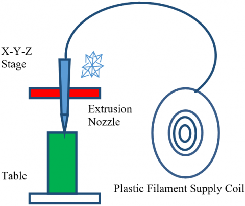
Fused Deposition Modeling (FDM) is the second most widely used rapid prototyping technology, developed in 1988 and commercially available in 1992. A plastic filament is unwound from a coil and supplies material to an extrusion nozzle. Nozzle is heated to melt the plastic has a mechanism which allows the flow of the melted plastic to be turned on and off [21]. The nozzle is mounted to an X-Y plotter type mechanism to trace out the part contours. There is a second extrusion nozzle for the support material (different from the model material). Nozzle is moved over the table in the required geometry, it deposits a thin bead of extruded plastic to form each layer and plastic hardens immediately after being squirted from the nozzle and bonds to the layer below. This process continued and part is buildup layer by layer. The schematic diagram of the FDM machine used in the experimentation is shown in Figure 1. A CAD model, created in CATIA V6, is first tessellated and sliced into layers of 0.1mm thickness to get contour information of each layer. In this study PLA plastic material is used for both build as well as support material.
Figure 1. Fused deposition modelling system
2.2 Details of PolyJet machine
Figure 2. PolyJet 3D Printing system
PolyJet 3D printing technology is developed by Israeli company Objet Geometries Ltd in 2000. It is a potentially encouraging replacement for stereolithography. In this method photopolymers are used for both build as well as support material. Inkjet head is use to layer wise deposition for both builds and support materials. It subsequently completely cures each layer after it is deposited with a UV flood lamp mounted on the print head. The support material which is removed by washing it away with pressurized water in a secondary operation. In this work RGD-840 was used as build material and SUP705 for support materials. Thickness of each layer is around 28 µm. The schematic diagram of the polyjet machine used in the experimentation is shown in Figure 2.
2.3 3-D modelling of the scaled model radial engine connecting rod
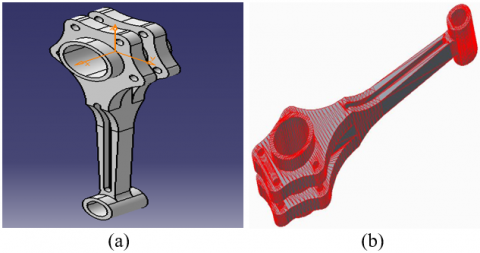
In the recent years, digital fabrication has slowly infiltrated the field of prototype making. At present there are more than twenty different types of 3D printers are available for the rapid prototyping. In order to analyze the effect of DA, shape error, surface roughness, cost of prototype and tolerance grade scaled model of radial engine connecting rod was consider as a case study. For creating the geometry 3D CAD software CATIVA V6 was used. Figure 3 shows the dimensions of the selected component. The 3D CAD model of the specimen used in the experiment is as shown in Figure-4(a). RP used standard .STL file format only. The sliced model is as shown in Figure 4(b).
Figure 3. Dimension of the component
Figure 4. (a): 3D CAD Model of Connecting Rod; (b): Sliced Model of Connecting Rod
2.4 Digital fabrication of the component
For comparing the process capability of the selected RP technology (Objet30, Ultimaker and MakerBot) component fabricated at the optimum process parameters conditions of each printer. VeroBlue840 was used as the build material and SUP705 as support material for the Objet30 printer. For Ultimaker and MakerBot, polylactic acid (PLA) was used as build and support material both. Figure 5 shows the printing of automotive component through Objet30. Figure 6(a) shows the fabricate component by Objet30, Figure 6(b) shows the fabricated component through MakerBot and Figure 6(c) shows the generated component by Ultimaker.
Figure 5. Printing of automotive part by Objet30
Figure 6. (a) Connecting rod printed by Objet360 (polyjet) printer; (b) Connecting rod printed by MakerBot (FDM) printer; (c) Connecting rod printed by Ultimaker (FDM) printer
2.5 Measurement of dimension
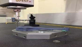
The coordinate measuring machine (CMM) as shown in Figure 7, was used for the measurement of linear as well as radial dimension of the automotive component (connecting rod and piston). For connecting rod total 12 linear dimension, 4 radial dimension and 4 circular dimensions were measured. Total 9 linear dimensions were measured along the print bed (X-Y axis) and 3linear dimension were measured perpendicular to the print bed (Y-Z axis) as shown in Table 1 and Table 2 respectively. Table 3 shows the measured radial dimensions for the connecting rods and Table 4 shows the circular dimensions.
Figure 7. Measurement of the dimensions of connecting rod
Table 1. Linear dimension along XY plane
|
Dimension |
CAD Dimension |
Objet 30 |
Ultimaker |
MakerBot |
%error Objet 30 |
%error Ultimaker |
%error MakerBot |
|
L1 |
202.56 |
200.75 |
200.69 |
200.09 |
0.89 |
0.92 |
1.22 |
|
L2 |
160.26 |
160.10 |
160.30 |
159.03 |
0.10 |
0.02 |
0.77 |
|
L3 |
92.40 |
92.07 |
92.00 |
91.38 |
0.36 |
0.43 |
1.10 |
|
L4 |
16.80 |
16.91 |
17.15 |
16.81 |
0.64 |
2.10 |
0.03 |
|
L5 |
33.00 |
32.21 |
33.25 |
32.35 |
2.41 |
0.77 |
1.97 |
|
L6 |
10.20 |
10.27 |
10.12 |
9.69 |
0.65 |
0.82 |
5.05 |
|
L7 |
15.60 |
15.26 |
15.30 |
16.00 |
2.18 |
1.93 |
2.55 |
|
L8 |
9.00 |
8.89 |
8.86 |
9.17 |
1.25 |
1.58 |
1.91 |
|
L9 |
33.00 |
32.86 |
30.82 |
32.98 |
0.43 |
6.61 |
0.06 |
|
Average % error |
0.99 |
1.69 |
1.63 |
||||
|
Maximum % error |
2.41 |
6.61 |
5.05 |
||||
|
STDEV |
0.81 |
1.97 |
1.54 |
||||
Table 2. Linear dimension along YZ plan
|
Dimension |
CAD Dimension |
Objet 30 |
Ultimaker |
MakerBot |
%error Objet 30 |
%error Ultimaker |
%error MakerBot |
|
T1 |
25.2 |
26.156 |
25.341 |
25.37 |
3.79 |
0.56 |
0.67 |
|
T2 |
42 |
42.36 |
41.564 |
41.79 |
0.86 |
1.04 |
0.50 |
|
T3 |
9.7 |
9.9 |
9.4 |
9.49 |
2.06 |
3.09 |
2.16 |
|
Average |
2.24 |
1.56 |
1.11 |
||||
|
Maximum |
3.79 |
3.09 |
2.16 |
||||
|
STDEV |
1.48 |
1.35 |
0.92 |
||||
Table 3. Circular dimension of connecting rod.
|
Dimension |
CAD Dimension |
Objet 30 |
Ultimaker |
MakerBot |
%error Objet 30 |
%error Ultimaker |
%error MakerBot |
|
D1 |
14.4 |
14.62 |
13.887 |
14.02 |
1.53 |
3.56 |
2.64 |
|
D2 |
21 |
21.1 |
20.657 |
20.71 |
0.48 |
1.63 |
1.38 |
|
D3 |
31.2 |
31.39 |
30.373 |
30.64 |
0.61 |
2.65 |
1.79 |
|
D4 |
37.8 |
37.67 |
37.233 |
37.19 |
0.34 |
1.5 |
1.61 |
|
Average |
0.74 |
2.34 |
1.86 |
||||
|
Maximum |
1.53 |
3.56 |
2.64 |
||||
|
STDEV |
0.54 |
0.97 |
0.54 |
||||
Table 4. Radial dimension of connecting rod
|
Dimension |
CAD Dimension |
Objet 30 |
Ultimaker |
MakerBot |
%error Objet 30 |
%error Ultimaker |
% error MakerBot |
|
R1 |
21.00 |
20.96 |
20.88 |
20.95 |
0.19 |
0.60 |
0.24 |
|
R2 |
2.50 |
2.46 |
2.45 |
2.44 |
1.68 |
1.98 |
2.40 |
|
R3 |
43.20 |
43.23 |
42.94 |
44.04 |
0.07 |
0.60 |
1.94 |
|
R4 |
7.80 |
7.79 |
7.76 |
7.99 |
0.19 |
0.52 |
2.44 |
|
Average |
0.53 |
0.92 |
1.75 |
||||
|
Maximum |
1.68 |
1.98 |
2.44 |
||||
|
STDEV |
0.77 |
0.70 |
1.04 |
||||
2.6 Measurement of roundness, cylindricity and flatness
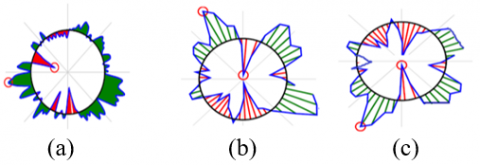
For checking the circularity of cylindrical portion (big end), roundness was measured by using coordinate measuring machine (CMM). Table 5 shows the measured value of form error (roundness, cylindricity and flatness) in the selected component. Figure 8 (a) shows the graphical representation of roundness in big end of the connecting rod of Objet30. Figure 8(b) and Figure 8(c) shows roundness in the component printed by Ultimaker and MakerBot respectively.
Figure 8. (a) Roundness of big end of the connecting rod of Objet 30; (b) Roundness of big end of the connecting rod of Ultimake; (c) Roundness of big end of the connecting rod of MakerBot
Table 5. Measurement of roundness, cylindricity and flatness.
|
S.N |
Measurement |
Objet30 (polyjet) |
MakerBot (FDM) |
Ultimaker (FDM) |
|
1 |
Roundness (mm) |
0.0686 |
0.1673 |
0.2917 |
|
2 |
Cylindricity (mm) |
0.0001 |
0.3426 |
0.0330 |
|
3 |
Flatness (mm) |
0.1630 |
0.3692 |
0.1678 |
2.7 Measurement of surface roughness
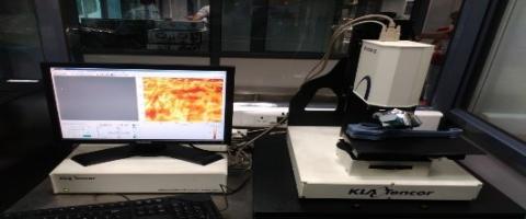
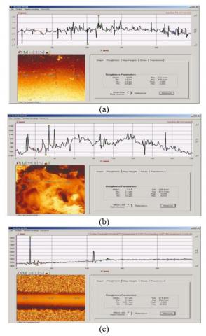
The measurement of surface roughness was performed by using optical profilometer as shown in Figure 9. Surface roughness of connecting rod was measured on top surface only. All the surface roughness parameters Ra, Rz and Rq were measured for both polyjet and FDM printed component. Table 6 shows the measured value of surface roughness. Figure 10 (a-c) shows the variation of surface roughness and 3D surface of SR for the printed component along the length.
Figure 9. Optical profilometer setup for the measurement of surface roughness
Figure 10. (a) surface roughness of MakerBot component; (b) Surface roughness of Ultimaker component; (c) Surface roughness of Objet30 component
Table 6. Measured surface roughness parameters
|
S.N |
Roughness Parameters |
Objet 30 |
MakerBot |
Ultimaker |
|
1 |
Average roughness height Ra (nm) |
214.4 |
332.4 |
505.9 |
|
2 |
Mean roughness height Rq (nm) |
290.1 |
478.3 |
613.1 |
|
3 |
Average peak to valley height Rz nm) |
1043.3 |
2304.2 |
2600.7 |
|
4 |
Peak roughness height Rp (nm) |
3423.3 |
2634.6 |
2331.3 |
|
5 |
Peak valley height Rv (nm) |
619.7 |
2530.7 |
1241.3 |
|
6 |
Peak height to peak valley height Rt nm) |
4043.0 |
5165.3 |
3572.6 |
3.1 Analysis of dimensional accuracy
Figure 11 shows the comparative analysis of average percentage error in DA of polyjet and FDM technology. Four different types of dimensions were selected for the analysis i.e. linear dimension in X-Y plane, linear dimension Y-Z plane, radial dimension and circular dimension. Table (1-4) shows the measured dimension in terms of average percentage error. It is observed that the dimensional accuracy of polyjet is better than the FDM components except along the Y-Z plane. It was also noticed that most of the dimensions are smaller than the CAD model dimension due to the shrinkage occurs during the sintering of component. In FDM shrinkage was found more as compared to polyjet technology. In FDM process there are always present air gapes which lead to the shrinkage. Along the Y-Z plane polyjet always produce dimension greater than the actual dimension because it forms a base on platform which yields the large size. The average percentage error in radial and circular dimension in the component produced by Objet30 was very less as compared to Ultimaker and MakerBot
Figure 11. Comparison of average percentage error in dimensions of polyjet and FDM
3.2 Analysis of form error
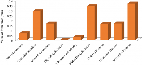
Figure12 highlights the comparison of form error (circularity, cylindricity and flatness) in the selected component generated by Objet30, Ultimaker and MakerBot printer. Experimental results raveled that polyjet technology have minimum form error as compared to the FDM. The measured value of form error is as reported in Table 5. For perfect cylinder the value of cylindricity is ‘0’. In our analysis it was found that cylindricity in the component fabricated by objet 30 is 0.0001, which is close to ‘0’.
Figure 12. Form error comparison of polyjet and FDM technology
3.3 Analysis of surface roughness parameters
Figure 13. Roughness parameters comparison of polyjet and FDM technology
Table 6, shows the measured value of various surface roughness parameters namely; average surface roughness (Ra), mean average surface roughness height (Rq) and average peak to valley height (Rz). The variation of surface roughness and 3D plots of the surface roughness parameters are as shown in Figure 10 (a-c) The completive analysis of the measured surface roughness is as shown in Figure 13. The experimental results revealed that component generated through polyjet technology have superior surface quality than FDM components. The roughness parameter Rz is much greater than Ra and Rz value, it implies that the surface irregularities is high in the components fabricated by using additive manufacturig technology.
3.4 Cost analysis
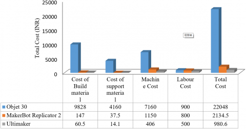
Cost analysis of additive manufacturing is important parameters for the designers while selecting the RP technology for printing the components. Cost analysis is very difficult for any RP technology because it depends on the number of factors which are locally vary place to place. However in this paper cost analysis was calculated as per the Indian scenario. The factors which are mainly influence the cost are amount of materials (build and support) consume, machine cost and labors cost. Total cost was calculated by using Eq. (1). Figure 14 show the summary of cost analysis report of this study.
Tc = Cb*Ab+Cs*As+ (tpre + tpost) Clc +tpre* Cm (1)
where, (Tc) is the total cost in (INR), Cb is the unit cost per kg of build material in (INR), Cs is the unit cost per kg of support material in (INR), Ab is the amount of build material consumed in (Kg), As is the amount of support material consumed in (Kg), tpre is the preprocessing time in (hrs), tpost is the post processing time in (hrs), Clc is the labour cost and Cm is the machine cost in (hrs).
Figure 14. Cost comparison of prototype fabricated by different 3D printers
3.5 Calculation of tolerance IT grade
For checking the tolerance grade of fabricated component ISO UNI EN 20286-I (1995) and DIN 16901 standard was considered. The measured dimension was used to evaluate tolerance unit ‘n’ derived from the fundamental tolerance ‘i’. The fundamental tolerance ‘i’ is used for the range of nominal dimension. The fundamental tolerance ‘i’ and tolerance unit ‘n’ can be expressed by using the following Equation 2 and Equation 3 respectively Maurya et al. [22].
i=0.453√D+0.001D (2)
n=1000(|Dn−Dm|i) (3)
where, ‘D’ is the geometric mean diameter, Dn is the nominal dimension and Dm is the measured dimension. Table 7 shows the IT grades for each linear dimension of the component fabricated by Objet30, Ultimaker and MakerBot 3D printers. Results revealed that tolerance in the linear dimension depends on the size and orientation of the component. Within the same component different dimension have different tolerance grade in each selected technology. The lower value of IT grade implies that better dimensional accuracy. Table 8 shows the IT grade of radial dimension. Likewise linear dimension radial dimension also have different IT grade for the different size. Most of the radial dimension generated through Objet30 have lower IT grade.
Table 7. IT grade for linear dimension as per the DIN 16901 standards
|
Dimension |
Objet 30 (polyjet) |
Ultimaker (FDM) |
MakerBot (FDM) |
||||||
|
LD |
n |
IT grade |
LD |
n |
IT grade |
LD |
n |
IT grade |
|
|
L1 |
200.75 |
267.5 |
IT11 |
200 |
276.4 |
IT11 |
200 |
97.5 |
IT9 |
|
L2 |
160.1 |
28.6 |
IT7 |
160 |
7.1 |
IT3 |
159 |
191.0 |
IT11 |
|
L3 |
92.07 |
72.5 |
IT9 |
92 |
87.9 |
IT10 |
91.3 |
151.6 |
IT11 |
|
L4 |
16.91 |
66.2 |
IT10 |
17.1 |
210.7 |
IT13 |
16.8 |
60.2 |
IT10 |
|
L5 |
32.21 |
279.3 |
IT13 |
33.2 |
88.4 |
IT10 |
32.3 |
49.5 |
IT9 |
|
L6 |
10.27 |
42.1 |
IT9 |
10.1 |
48.2 |
IT10 |
9.69 |
349.2 |
IT14 |
|
L7 |
15.26 |
204.7 |
IT13 |
15.3 |
180.6 |
IT13 |
16 |
445.5 |
IT15 |
|
L8 |
8.89 |
87.3 |
IT11 |
8.86 |
111.1 |
IT12 |
9.17 |
222.2 |
IT14 |
|
L9 |
32.86 |
49.5 |
IT9 |
30.8 |
770.6 |
IT15 |
32.9 |
42.4 |
IT9 |
|
T1 |
26.156 |
436.1 |
IT14 |
25.3 |
64.3 |
IT11 |
25.3 |
358.6 |
IT14 |
|
T2 |
42.36 |
127.3 |
IT11 |
41.5 |
154.1 |
IT11 |
41.7 |
201.5 |
IT12 |
|
T3 |
9.9 |
158.7 |
IT13 |
9.4 |
238.1 |
IT14 |
9.49 |
325.4 |
IT14 |
Table 8. IT grade for Radial dimension as per the ISO standards for plastic component
|
Dimension |
Objet 30 (polyjet) |
Ultimaker (FDM) |
MakerBot (FDM) |
||||||
|
RD |
(n) |
IT grade |
RD |
(n) |
IT grade |
RD |
(n) |
IT grade |
|
|
D1 |
31.39 |
67.2 |
IT10 |
30.373 |
292.3 |
IT13 |
30.64 |
265.1 |
IT13 |
|
D2 |
37.67 |
46.0 |
IT9 |
37.233 |
200.4 |
IT12 |
37.19 |
169.7 |
IT12 |
|
D3 |
14.62 |
132.5 |
IT12 |
13.887 |
308.9 |
IT14 |
14.02 |
361.2 |
IT14 |
|
D4 |
21.1 |
45.6 |
IT9 |
20.657 |
156.5 |
IT12 |
20.71 |
177.9 |
IT12 |
|
R1 |
20.96 |
18.2 |
IT7 |
20.88 |
54.7 |
IT11 |
20.95 |
22.8 |
IT8 |
|
R2 |
2.46 |
67.5 |
IT12 |
2.45 |
84.3 |
IT12 |
2.44 |
101.2 |
IT13 |
|
R3 |
43.23 |
10.6 |
IT5 |
42.94 |
91.9 |
IT10 |
44.04 |
296.9 |
IT13 |
|
R4 |
7.79 |
7.9 |
IT6 |
7.76 |
31.7 |
IT9 |
7.99 |
150.0 |
IT12 |
In this paper comparative study of process capability of three different 3D printers namely Objet30, Ultimaker and MakerBot have been evaluated. For the purpose of analyzing this technology automotive component (connecting rod) was selected. comparison was carried out on the basis of linear DA, radial DA, circular DA form error (circularity, cylindricity and flatness), surface roughness, cost of the component and IT tolerance grade. ISO UNI EN 20286-I (1995) and DIN 16901 standards was used for the evaluating IT grades for each selected dimension. The major finding of this research work was highlighted as:
(1) The average percentage error in DA along XY plane (build platform) for Objet30 (0.99 %), Ultimaker (1.69 %) and Makerbot (1.63 %) were found. Objet30 has minimum percentage error along the XY plane.
(2) The average percentage error in DA along YZ plane (perpendicular to build platform) for Objet30 (2.24 %), Ultimaker (1.56 %) and Makerbot (1.11 %) were found. MakerBot have minimum percentage error along the YZ plane.
(3) In case of radial dimension average percentage of DA of objet30 (0.53 %), Ultimaker (0.92 %), MakerBot (1.75 %) were found.
(4) Average percentage error in circular dimension of Objet30 (0.74 %), Ultimaker (2.34 %) and MakerBot (1.86) were found.
(5) Component generated through polyjet technology (objet30) have minimum form error. The measured value of form error for Objeted-30 was roundness (0.0686 mm), cylindricity (0.0001 mm) and flatness (0.1630 mm).
(6) All the surface roughness parameters Ra, Rq, Rt, Rv, Rz and Rv was measured by using optical profilometer. Table shows the measured value of surface roughness in (nm). Component fabricated through Objet30 have minimum surface roughness.
(7) Cost analysis of the component was calculated based on the build material, support material, labour cost and machine cost. Table shows the Summary of cost report of three different technologies for our selected component. Total cost prototype generated through Objet 30 is very high as compared to Ultimaker and MakerBot.
(8) Within the same component different dimension have different tolerance for each printer. Comparatively IT grade of the dimensions in the part fabricated by Objet30 have lower IT grade which implies that better DA.
[1] Jaina, P., Kuthe, A.M. (2013). Feasibility study of manufacturing using rapid prototyping: FDM approach. Procedia Engineering, 63: 4-11. https://doi.org/10.1016/j.proeng.2013.08.275
[2] Maurya, N.K., Rastogi, V., Singh, P. (2018). Experimental investigations for improving part strength in fused deposition modeling. International Journal of Engineering & Technology, 7(4.39): 457-461. https://doi.org/10.14419/ijet.v7i4.39.24124
[3] Kumar, K., Kumar, G.S. (2015). An experimental and theoretical investigation of surface roughness of poly-jet printed parts. Virtual and Physical Prototyping, 10(1): 23-34. https://doi.org/10.1080/17452759.2014.999218
[4] Maurya, N.K., Rastogi, V., Singh, P. (2019). Experimental and computational investigation on mechanical properties of reinforced additive manufactured component. EVERGREEN Joint Journal of Novel Carbon Resource Sciences & Green Asia Strategy, 6(3): 207-214.
[5] Senthilkumaran, K., Pandey, P.M., Rao, P.V.M. (2012). Statistical modeling and minimization of form error in SLS prototyping, Rapid Prototyping Journal, 18(1): 38-48. https://doi.org/10.1108/13552541211193485
[6] Melenka, G.W., Schofield, J.S. (2015). Evaluation of dimensional accuracy and material properties of the MakerBot 3D desktop printer. Rapid Prototyping Journal, 21(5): 556-571. https://doi.org/10.1108/RPJ-09-2013-0093
[7] Sood, A.K., Ohdar, R.K., Mahapatra, S.S. (2009). Improving dimensional accuracy of fused deposition modelling processed part using grey Taguchi method. Materials and Design, 30: 4243-4252. https://doi.org/10.1016/j.matdes.2009.04.030
[8] Singh, J., Singh, R., Singh, H. (2017). Experimental investigations for dimensional accuracy and surface finish of polyurethane prototypes fabricated by indirect rapid tooling: a case study. Prog Addit Manuf, 2(1-2): 85-97. https://doi.org/10.1007/s40964-017-0024-0
[9] Singh, R. (2011). Process capability study of polyjet printing for plastic components. Journal of Mechanical Science and Technology, 25(4): 1011-1015. https://doi.org/10.1007/s12206-011-0203-8
[10] Senthilkumaran, K., Pandey, P.M., Rao, P.V.M. (2009). Influence of building strategies on the accuracy of parts in selective laser sintering. Materials and Design, 30: 2946-2954. https://doi.org/10.1016/j.matdes.2009.01.009
[11] Nizam, A., Gopal, R.N., Naing, L., Hakim, A.B., Samsudin, A.R. (2006). Dimensional accuracy of the skull models produced by rapid prototyping technology using stereolithography apparatus. Archives of Orofacial Sciences, 1; 60-66.
[12] https://www.semanticscholar.org/paper/Dimensional-Accuracy-of-the-Skull-Models-Produced-Nizam-Naing/028d696644f241534b0ebd211a9c84e9789877a3#citing-papers, accessed on 16 December 2018.
[13] Pennington, R.C., Hoekstra, N.L., Newcomer, J.L. (2004). Significant factors in the dimensional accuracy of fused deposition modelling. Institution of Mechanical Engineers, 219(1): 89-92. https://doi.org/10.1243/095440805X6964
[14] Mohamed, O.A., Masood, S.H., Bhowmik, J.L. (2017). Experimental investigation for dynamic stiffness and dimensional accuracy of FDM manufactured part using IV-Optimal response surface design. Rapid Prototyping Journal, 23(4): 736-749. https://doi.org/10.1108/RPJ-10-2015-0137
[15] Onuh, S.O., Hon, K.K.B. (2011). Improving stereolithography part accuracy for industrial applications. The International Journal of Advanced Manufacturing Technology, 17(1): 61-68. https://doi.org/10.1007/s001700170210
[16] Gibson, I.R., Brent, D.S. (2015). 3D Printing, Rapid Prototyping, and Direct Digital Manufacturing. Additive Manufacturing Technology. Springer Science and Business Media, New York.
[17] Onuh, S.O., Hon, K.K.B. (2011). Integration of rapid prototyping technology into FMS for agile manufacturing. Integrated Manufacturing Systems, 12(3): 179-186. https://doi.org/10.1108/09576060110391138
[18] Zhou, J.G., Herscovici, D., Chen, C.C. (2000). Parametric process optimization to improve the accuracy of rapid prototyped stereolithography parts. International Journal of Machine Tools & Manufacture, 40(3): 363-379. https://doi.org/10.1016/S0890-6955(99)00068-1
[19] Farzadi, A., Waran, V., Solati-Hashjin, M., Rahman, Z.A.A., AsadiM., Osman, N.A.A. (2015). Effect of layer printing delay on mechanical properties and dimensional accuracy of 3D printed porous prototypes in bone tissue engineering. Ceramics International, 41(7): 8320-8330. https://doi.org/10.1016/j.ceramint.2015.03.004
[20] Stevinson, B., Bourell, D.L., Joseph, J.B. (2006). Dimensional stability during post-processing of selective laser sintered ceramic performs. Virtual and Physical Prototyping, 1(4): 209-216. https://doi.org/10.1080/17452750601107003
[21] Cho, U., Wood, K.L., Crawford, R.H. (1998). Online functional testing with rapid prototypes: A novel empirical similarity method. Rapid Prototyping Journal 4(3): 128-138. https://doi.org/10.1108/13552549810223000
[22] Chang, D.Y., Huang, B.H., (2010). parts using the fused deposition modeling process. The International Journal of Advanced Manufacturing Technology, 53(9-12): 1027-1037. https://doi.org/10.1007/s00170-010-2882-1
[23] Maurya, N.K., Rastogi, V., Singh, P. (2019). Investigation of dimensional accuracy and international tolerance grades of 3D printed polycarbonate parts. Materials Today: Proceedings. https://doi.org/10.1016/j.matpr.2019.06.007