Abdelghani Aib | Djalal Eddine Khodja* | Salim Chakroune | Loutfi Benyettou
OPEN ACCESS
This article provides a full hardware implementation for direct torque control (DTC) of an asynchronous motor (AM) on the Field Programmable Gate Array (FPGA). Due to its high processing frequency, the FPGA circuit presents an alternative for achieving a high performance DTC implementation. This cannot be achieved by any DSP or microcontroller application. The proposed hardware architecture implements three components of DTC control strategy (the integral proportional speed regulator, the estimation and the switching blocks). This implementation has the advantage of being faster, more efficient and with minimum hardware resources on the target FPGA board. The hardware architecture of the DTC control was designed and simulated in Matlab / Simulink using XSG blocks, then synthesized with the Xilinx ISE 14.2 tool, implemented and validated on the Xilinx Virtex-4 FPGA circuit by Hardware in the Loop process.
hardware, co-simulation, Xilinx generator system, induction machine control, DTC, ML402
In the field of variable speed electric drive, the majority of achievements are built around the asynchronous machine, this is due to their advantages such as robustness, reliability and low cost. Advances in power electronics and microelectronics have made it a formidable competitor in the fields of variable speed and rapid torque control [1].
Direct torque control (DTC) was first introduced by Dopenbrock and Takahashi [2, 3]. It is one of the methods used in variable frequency drives such as induction motor drives. Its fame was derived from the simplicity of its structure, its high efficiency and low cost [4, 5].
An efficient DTC of induction motor drive systems involves fast computational units. Digital Signal Processing (DSP) and microprocessors are frequently used in such applications [6-8]. But these devices have a limited processing speed because of serial calculations; this affects its performance especially in real time application. The use of FPGA circuits offers an appropriate solution for fast calculations [9-14].
However, the most difficult parts of DTC control to implement are the torque and flux estimators [15]. In fact, complex numerical calculations are called upon during implementation, such as binary multiplication, the Arctan function and also the root mean square [16, 17].
The number of hardware resources in FPGA circuit being limited, some efforts must be made to minimize these resources through a simple design methodology proposed in this article, and which will be applied to proposed material architectures [18, 19].
This methodology is based on the illustration of a compromise that performs an optimization of hardware architecture while preserving the good performances of electrical drive system consisting of a voltage inverter and an asynchronous machine.
This paper presents a new conception of the implementation of DTC control for the asynchronous machine drive. The validation of the implementation is done by hardware co-simulation of the proposed architecture on the FPGA ML402 platform.
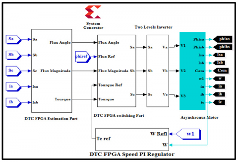
The direct torque control of asynchronous machine is based on the application of different voltage vectors of the inverter, which are controlled in two variables are the stator flux and the electromagnetic torque by hysteresis regulators (Figure 1).
The power converter is a conventional two-level voltage inverter. These values are directly estimated from the stator voltages determined with the constant voltage Udc and the Boolean switching commands (Sa, Sb, Sc).
The estimated values of torque and of stator flux are compared respectively with their estimated reference values and; the comparison results are the inputs to the hysteresis cycle comparators. The controlled electromagnetic torque is provided by the PI speed controller.
Moreover, several parameters must be determined in order to estimate the stator flux and the electromagnetic torque. Their models are adapted to the needs of controlled training.
First, the stator currents a-b-c are transformed into α-β coordinates, and the stator voltages in the α-β frame of reference are determined according to the switching state (Sa, Sb and Sc) produced by the switching table.
Using the stator current and voltage, the stator flux can be estimated in coordinates (α-β) as follows [17]:
$\emptyset_{s \alpha}=\int\left(V_{s \alpha}-R_{s} i_{s \alpha}\right) d t$ (1)
$\emptyset_{s \beta}=\int\left(V_{s \beta}-R_{s} i_{s \beta}\right) d t$ (2)
With:
($\emptyset_{s \alpha}$, $\emptyset_{s \beta}$): Stator flux.
($i_{s \alpha}$, $i_{s \beta}$): Stator currents.
($V_{s \alpha}$, $V_{s \beta}$): Stator voltages.
$R_{s}$ Stator resistance.
To perform the integral function, the Euler approach is used with a sampling time (Ts), the systems (1) and (2) become as follow:
$\emptyset_{s \alpha}=\emptyset_{s \alpha O l d}+T_{s}\left(V_{s \alpha}-R_{s} i_{s \alpha}\right)$ (3)
$\emptyset_{s \beta}=\emptyset_{s \beta O l d}+T_{s}\left(V_{s \beta}-R_{s} i_{s \beta}\right)$ (4)
Finally, the electromagnetic torque (Te) can be estimated by Mohammedi et al. [17]:
$T_{e}=P\left(\emptyset_{s \alpha} i_{s \beta}-\emptyset_{s \beta} i_{s \alpha}\right)$ (5)
With (2p) is the machine peer pole number.
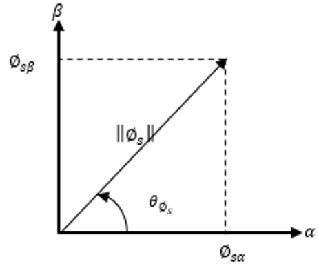
For the stator flux magnitude ($\left\|\emptyset_{s}\right\|$) and Angle ($\theta_{\emptyset_{s}}$) can be obtained by Cartesian to Polar Coordinates Transformation (Figure 2).
Unfortunately, the standard mathematics transformation based on the formulas:
$\left\|\emptyset_{s}\right\|=\sqrt{\emptyset_{s \alpha}^{2}+\emptyset_{s \beta}^{2}}$
And
$\theta_{\emptyset_{s}}=\operatorname{ArcTan}\left(\frac{\emptyset_{s \beta}}{\left\|\emptyset_{s}\right\|}, \frac{\emptyset_{s \alpha}}{\left\|\emptyset_{s}\right\|}\right)$
Figure 1. Functional schemes of DTC control
Is not always implantable on hardware and often requires a lot of device resources because of excessive resources functions such as the binary multiplication and division, the Root Mean Square and the ArcTan function. To overcome this constraint, our estimators use a version of CORDIC (Coordinate Rotational Digital Computer) algorithm to calculate the statorique flux magnitude and angle, using simply implementable operators on FPGA. In addition, subtraction and binary digits shift [20].
In ref. [5] the authors used two binary multiplier and 62 bits no restoring root mean square [18] to calculate flux magnitude, and Sutikno et al. [5] used two binaries multiplier, Root Mean Square generalized CORDIC bloc and ArcTan generalized CORDIC bloc to estimate flux magnitude and angle. Two binary multiplier and Root Mean Square generalized CORDIC bloc was used to estimate flux magnitude in ref. [5]. Our solution use only reduced CORDIC bloc and one multiplier to estimate simultaneously the flux magnitude and angle.
Figure 2. Stator flux cartesian to polar coordinates transformation
3.1 Implementation of flux and torque estimator
In this part, flux and torque estimators are designed based on FPGA circuits to improve DTC induction motor drives.
This allows precise calculations and very fast response times. To do this, a discrete integration operation calculation was performed for the magnitude of the stator flux using Euler's recursive approach and for the angle, the CORDIC Cartesian Polar Coordinate algorithm was used [20].
In fact, for verification and development of the algorithms of estimators in FPGA circuit we will use the modeling tool known as XSG developed by Xilinx intended for MATLAB / SIMULINK. The main role of the SXG tool is to transform the DTC model into hardware format for implementation on FPGA. Then it generates VHDL code without any difficult programming. Indeed, the implementation time of this algorithm turns out to be reduced.
3.1.1 Implementation of α-β stator current and voltage calculator
XSG design of (α-β) stator voltage and current calculator are shown in Figure 3.
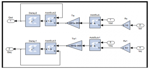
3.1.2 Implementation of aß stator fluxes estimation
The Figure 4 shows the hardware design for the estimator of α-β stator flux using the system generator.
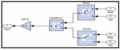
3.1.3 Implementation of torque estimator
Figure 5 shows the torque estimator design of proposed DTC using System Generator.
Figure 3. FPGA α-β stator current and voltage calculator implementation
Figure 4. Hardware design for estimator of α-β stator flux using System Generator
Figure 5. Hardware design for the torque estimator using System Generator
3.1.4 Implementation of CORDIC $\emptyset_{s}$ cartesian to polar coordinate transformation
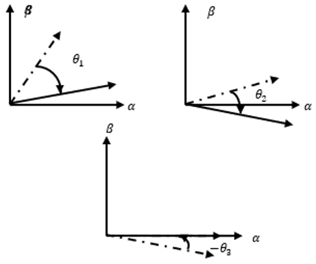
The CORDIC algorithm is designed to perform a vector rotation of the vector (X, Y) through an angle θ, resulting in new vector (X’, Y’) (Figure 6) [20].
$\left\{\begin{array}{c}x^{\prime}=(x \cos (\theta)-y \sin (\theta)) \\ y^{\prime}=(y \cos (\theta)+x \sin (\theta)) \\ \theta^{\prime}=\theta\end{array}\right.$ (6)
The role of the CORDIC algorithm is to make a vector rotation by successive and smaller sequences of rotations, each angle at an (2-i), called micro-rotations.
Eq. (7) shows the expression of the ith iteration where i is the iteration index from 0 to n [20].
$\left\{\begin{array}{c}x_{i+1}=x_{i}-\alpha_{i} y_{i} 2^{-i} \\ y_{i+1}=y_{i}+\alpha_{i} x_{i} 2^{-i} \\ \theta_{i+1}=\theta_{i}+\alpha_{i} \operatorname{atan}\left(2^{-i}\right) \\ \alpha_{i}=(+1 \text { or }-1)\end{array}\right.$ (7)
where, $\alpha_{i}$ is the direction of rotation.
In fact, a micro-rotation is expressed as a simple operation of shift and addition subtraction. Eq. (8) shows the vector rotation expression for the nth iteration [20].
$\left\{\begin{array}{c}x_{n}=\prod_{i=0}^{n-1} \cos \left(\operatorname{atan}\left(2^{-i}\right)\right)\left(x_{i}-\alpha_{i} y_{i} 2^{-i}\right) \\ y_{n}=\prod_{i=0}^{n-1} \cos \left(\operatorname{atan}\left(2^{-i}\right)\right)\left(y_{i}+\alpha_{i} x_{i} 2^{-i}\right) \\ \theta_{n}=\sum_{i=0}^{n-1} \alpha_{i} \operatorname{atan}\left(2^{-i}\right) \\ \alpha_{i}=(+1 \text { or }-1)\end{array}\right.$ (8)
The outputs of Eqns. (7) and (8) of the CORDIC algorithm are equivalent to a vector rotation or vector translation scaled by a constant Zn. In this case the constant Zn is known as the CORDIC scale factor. So, the Taylor series expansion of $\cos \left(\operatorname{atan}\left(2^{-i}\right)\right)$ is $\left(1+2^{-2 i}\right)^{-1 / 2}$. Hence, the constant Zn can be expressed as: $Z n=\prod_{i=0}^{n-1} \frac{1}{\left(1+2^{-2 i}\right)^{-1 / 2}}$ [20].
Figure 6. Example of CORDIC vector rotation
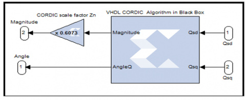
The CORDIC scale factor of Zn depends only on the number of iterations ‘N’. In other words, only the functional Rotation and Translation configurations: Rectangular to Polar and Polar to Rectangular are affected by the CORDIC scale factor. However, once these functional configurations are selected, the CORDIC core offers the possibility of multiplying by Zn to cancel the scale factor. For n=10, Zn=0.6073.
The previous CORDIC algorithm is implemented in hardware by VHDL architecture:
Entity CORDIC is
Port (Qsd: in STD_LOGIC_VECTOR (15 down to 0);
Qsq: in STD_LOGIC_VECTOR (15 down to 0);
Magnitude: out STD_LOGIC_VECTOR (15 down to 0);
Angle Q: out STD_LOGIC_VECTOR (15 down to 0));
End CORDIC;
The VHDL CORDIC code is implemented in Black Box with XSG (Figure 7):
Figure 7. CORDIC algorithm with XSG
3.2 Implementation of sectors selection
The block below determines in which sector number the stator flux vector is located at a given sampling time. In fact, the coordinate plane α-β is subdivided into 6 sectors. This is done by comparing the flow angle with the boundaries of each sector. For this, we use two comparators, two adders and a multiplexer in XSG (Figure 8):
Figure 8. XSG of sectors selection implementation
3.3 Implementation of hysteresis controller
Figure 9 shows the XSG implementation of three and two level hysteresis comparators of flux and torque respectively. As for the estimated flux and torque values are compared with the reference values (torque and flux control values).
3.4 Implementation of Takahashi switching table
The switching signals of the IGBTs of the inverter are determined according to the comparison results of hysteresis regulators from switching table shown in Table 1.
The table consists of null and active vectors. The zero vectors are (0,0,0) and (1,1,1) which stop the field vector, thus reducing the torque. While, the other six active vectors advance the field forward and resulting in increased torque [18].
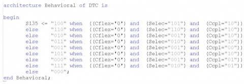
The Takahashi switching table is implemented by VHDL hardware architecture. The VHDL hardware description language allows us to define the inputs/outputs of our architecture. An input bit for flux error $\Delta \bar{\varphi}_{s}$ (0 or 1), two input bits for torque error $\Delta T_{e}$ (-1,0 or 1), three input bits for sectors selection (N1, N2, N3, N4, N5 or N6) and three output bits for $\bar{V}_{s}$ (Sa, Sb and Sc). The following figure presents the inputs/outputs of the proposed architecture and the corresponding VHDL code (Figure 10).
Figure 9. Hysteresis comparators XSG implementation
Figure 10. Takahashi switching table VHDL architecture
The VHDL architecture of Takahashi switching table is implemented by an assignment in the competitive mode (Figure 11):
$\bar{V}_{\text {output }}<=\bar{V}_{1}$, or $\bar{V}_{2}$, or $\bar{V}_{3}$, or $\bar{V}_{4}$ or $\bar{V}_{5}$, or $\bar{V}_{6}$, or $\bar{V}_{0}, \bar{V}_{7}$
Table 1. Switching table for DTC
|
Vi = (Sa, Sb, Sc) |
|||||||
|
$\phi$, Te, N |
N=1 |
N=2 |
N=3 |
N=4 |
N=5 |
N=6 |
|
|
$\phi$=1 |
Te=1 |
(1,1,0) |
(0,1,0) |
(0,1,1) |
(0,0,1) |
(1,0,1) |
(1,0,0) |
|
Te=0 |
(1,1,1) |
(0,0,0) |
(1,1,1) |
(0,0,0) |
(1,1,1) |
(0,0,0) |
|
|
Te=-1 |
(1,0,1) |
(1,0,0) |
(1,1,0) |
(0,1,0) |
(0,1,1) |
(0,0,1) |
|
|
$\phi$=0 |
Te=1 |
(0,1,0) |
(0,1,1) |
(0,0,1) |
(1,0,1) |
(1,0,0) |
(1,1,0) |
|
Te=0 |
(0,0,0) |
(1,1,1) |
(0,0,0) |
(1,1,1) |
(0,0,0) |
(1,1,1) |
|
|
Te=-1 |
(0,0,1) |
(1,0,1) |
(1,0,0) |
(1,1,0) |
(0,1,0) |
(0,1,1) |
|
Figure 11. VHDL implementation of Takahashi switching table
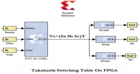
The output signal vector $\bar{V}_{s}=\left(\begin{array}{l}\mathrm{Sa} \\ \mathrm{Sb} \\ \mathrm{Sc}\end{array}\right)$ divides by slice to generate three signals (Sa, Sb and Sc) of the inverter control. A slice extract a given range of bits from each input sample and presents it at the output (Figure 12).
Figure 12. Takahashi switching table on FPGA
3.5 Implementation of speed regulator
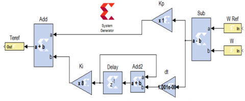
In DTC control the speed regulation is realized by a conventional proportional integral regulator type of the following form (Figure 13):
Figure 13. Principle of the speed PI regulator
Figure 14. XSG implementation of speed PI regulator
The hardware implementation of speed PI regulator is done by adding the effects of the proportional and integral actions for speed error.
The proportional action is simply realized by a multiplier between the speed error and the Kp coefficient. The integral action is realized by the hardware implementation of the Euler integration approach.
Figure 14 shows the hardware design for the speed PI regulator using the System Generator.
4.1 Matlab/Simulink and XSG/Xilinx simulations
The implementation of the proposed architectures has been carried out using the XSG blocks available on Simulink library. Once a system designed gives the desired simulation results, the bitstream file and the Hardware-In-the-Loop block can be generated by system generator. The parameters of induction motor used in the co-simulation phase are presented in Table 2.
Table 2. Parameters of induction motor
|
Parameter |
Value |
|
RS |
10 $\Omega$ |
|
Rr |
6.3 $\Omega$ |
|
LS |
0.4642 H |
|
Lr |
0.4612 H |
|
Lm |
0.4212 H |
|
J |
0.02 kg.m2 |
|
P |
2 |
Figure 15 shows the DTC simulation blocks.
4.2 FPGA hardware co-simulation
4.2.1 Creating point to point Ethernet block for the hardware-in-the-loop
Once the simulation and temporal analysis are performed, the XSG hardware co-simulation process generates a bitstream file and a point-to-point Ethernet block for the HIL process. The generated block (Figure 16) replaces the hardware design already built (DTC estimation part and DTC control part).
The point to point Ethernet blocks (estimation part and control part) are connected to the inverter to run a HIL. In this situation the models of motor and inverter are simulate in Matlab/Simulink environment, and XSG architectures of DTC Estimation Part or DTC Control part are achieved in the ML402 FPGA device. The validation of hardware-in-the-loop is executed by connecting the target device to the PC with an Ethernet cable.
4.2.2 Synthesis results
In this step, the VHDL codes are synthesized in order to convert them into XSG blocks. The resource usage of the DTC implementation on the FPGA is shown in Table 3. The latter presents the necessary information of Input Output blocks number, Slices Registers, Slice LUTs (Lock Up Tables) and number of DSP.
The proposed architecture significantly reduced the hardware resources of the DTC FPGA implementation compared to the presented [16, 19].
In this work, the maximum combinatorial path delay: 4.317ns (232 MHz). While in articles [19] the maximum clock frequency is 54 MHz using DSPACE (digital signal processing and control engineering).
In ref. [9] the sampling time is equal to 50 µs. However, the execution time is too long compared to the FPGA.
4.2.3 High level simulation of the flux and torque estimator
The proposed flux and torque estimator architecture is validated by co-simulation process in Matlab/Simulink environment with XSG tools and ML402 device.
Figure 15. Proposed DTC XSG/Simulink simulation blocks
Figure 16. Proposed DTC hardware co-simulation
Table 3. Used resources
|
Target Device: ML402 Virtex-4 xc4vsx35-10ff668 |
|||||
|
Logic Utilization |
Estimation |
Control |
Total |
Available |
Utilization |
|
Number of bonded IOBs |
58 |
90 |
|
448 |
|
|
Number of slices registers |
1,471 |
1,547 |
3018 |
30,720 |
10% |
|
Number of slice LUTS |
5,409 |
2,361 |
7770 |
30,720 |
25% |
|
Number of DSP48Es |
10 |
00 |
10 |
192 |
05% |
The estimated stator flux in the plan α-β in Figure 17.
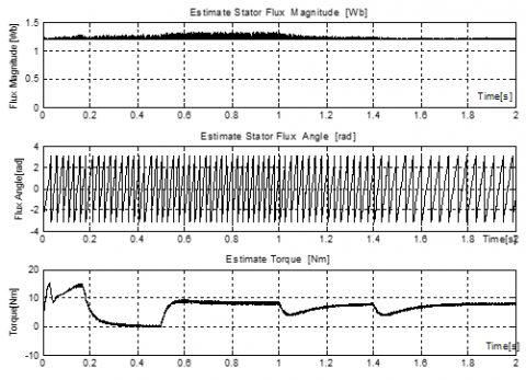
In Figure 18, the calculate torque, flux angle and flux magnitude are presented for induction motor start-up phase.
Figure 17. The stator flux in the plan α-β
Figure 18. Behavior of estimate flux and torque
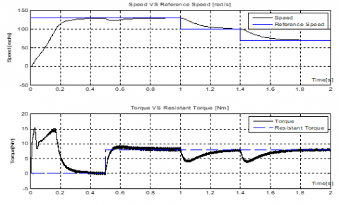
Figure 19. Behavior of induction motor speed and torque
4.2.4 High level simulation of the DTC control performances
The response waveforms of induction motor speed and torque VS differ reference speed and resistant torque are shown in Figure 19.
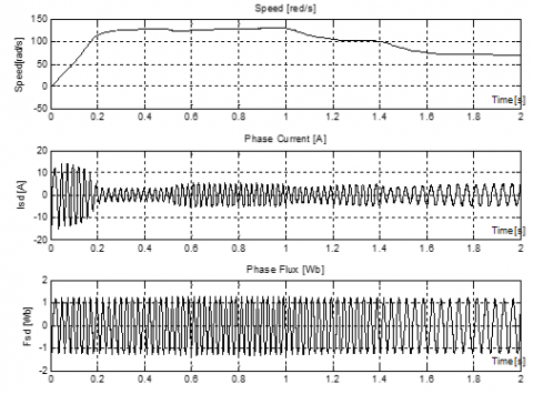
The evolution of speed, phase current and flux are presented in Figure 20. Figure 21, show the behavior of induction motor torque Vs reference torque.
Figure 20. Behavior of induction motor speed, phase currents and phase flux
Figure 21. Behavior of induction motor torque Vs reference torque
The results obtained during the hardware co-simulation phase proved that the implementation was successful. Nevertheless, there is the nourishment of certain fluctuations at the levels of the curves of parameters such as current, torque and flux. This is due to the attempt to choose the optimal size of the data in order to achieve an accurate calculation and minimum internal resources of the FPGA circuit. Indeed, it is necessary to reduce the sampling time in order to reduce the torque ripples. Furthermore, the fluctuation of the estimated torque and flux does not matter on the dynamic responses of the motor, even the speed has not been affected.
In this paper, an implementation of full direct torque control DTC was made using hardware co-simulation to improve the control of induction motor. The bitstream file generated by Xilinx System Generator from the hardware design is implemented on the FPGA circuit. Then a hardware-in-the-loop validation was carried out for several operating modes of induction motor. The results of implementation using the XSG, Simulink and FPGA Virtex-4 cards have shown that the proposed architecture offers better performance, particularly with regard to processing speed and resource use. As a forthcoming application, we will integrate an artificial intelligence technique into the architecture of the DTC control to reduce the disadvantages of this command.
This work was supported by Electrical Engineering Laboratory (LGE) at the University of Mohamed Boudiaf-M’sila, (Algeria) and Signals & Systems Laboratory, Institute of Electrical and Electronic Engineering Boumerdes University, (Algeria). We like to thank Dr. Djalal Eddine Khodja and Dr. Salim Chakroune for their help in the preparation of this paper.
[1] Sudheer, H., Kodad, S., Sarvesh, B. (2018). Improvements in direct torque control of induction motor for wide range of speed operation using fuzzy logic. Journal of Electrical Systems and Information Technology, 5(3): 813-828. https://doi.org/10.1016/j.jesit.2016.12.015
[2] Takahashi, I., Ohmori, Y. (1989). High-performance direct torque control of an induction motor. IEEE Transaction on Industrial Application, 25(2): 257-264. https://doi.org/10.1109/28.25540
[3] Depenbrock, M. (1988). Direct self control of inverter-fed induction machines. IEEE Transaction on Power Electronics, 3(4): 420-429. https://doi.org/10.1109/63.17963
[4] Najib, E., Derouich, A., Ghzizal, A., Otahhir, S., Chebabhi, A., Mourabit, Y., Mohammed, T. (2019). Improvement techniques of direct torque control for induction motor drives - A review. Protection and Control of Modern Power Systems, 4(11). https://doi.org/10.1186/s41601-019-0125-5
[5] Sutikno, T., Idris, N., Jidin, A. (2011). A new fixed switching frequency direct torque controlled PMSM drives with low ripple in flux and torque. ITB Journal of Engineering Science, 43(3): 173-190. https://doi.org/10.5614/itbj.eng.sci.2011.43.3.2
[6] Bossoufi, B., Karim, M., Lagrioui, A., Ionitta, S. (2010). Performance analysis of direct torque control (DTC) for synchronous machine permanent magnet (PMSM). IEEE 16th International Symposium for Design and Technology in Electronic Packaging (SIITME), Pitesti, Romania, pp. 237-242. https://doi.org/10.1109/SIITME.2010.5649125
[7] Toh, C.L., Idris, N.R.N., Yatim, A.H.M. (2007). Design and implementation of TMS320C31 DSP and FPGA for conventional direct torque control (DTC) of induction machines. International Journal of Mechanical and Mechatronics Engineering, 3(2): 225-230. https://doi.org/10.5281/zenodo.1333566
[8] Selvarathinam, M., Deepika, T., Devipriya, D., Muthukumar, P. (2016). A novel FPGA based direct torque control for induction motor. Middle-East Journal of Scientific Research, 24(3): 787-793. https://doi.org/10.5829/idosi.mejsr.2016.24.03.23077
[9] Bharatiraja, C., Jeevanandam, S., Pratik. (2010). A system on chip (SOC) – high performance power drive applications - SVPWM based voltage source inverter. International Journal of Computer Applications, 2(9): 42-47. https://doi.org/10.5120/691-971
[10] Kowalski, C.T., Lis, J., Orlowska-Kowalska, T. (2007). FPGA implementation of DTC control method for the induction motor drive. The International Conference on Computer as a Tool EUROCON, Warsaw, Poland, pp. 1916-1921. https://doi.org/10.1109/EURCON.2007.4400657
[11] Krim, S., Gdaim, S., Mtibaa, A., Mimouni, F. (2015). FPGA-based implementation direct torque control of induction motor. International Journal of Power Electronics and Drive System (IJPEDS), 5(3): 293-304. http://doi.org/10.11591/ijpeds.v5.i3.pp293-304
[12] Sutikno, T., Idris, N.R.N., Jidin, A.Z., Daudm M. (2011). FPGA based high precision torque and flux estimator of direct torque control drives. IEEE Applied Power Electronics Colloquium (IAPEC), Johor Bahru, Malaysia, pp. 122-127. http://doi.org/10.1109/IAPEC.2011.5779871
[13] Kabache, N., Moulahoum, S., Houassine, H. (2014). Hardware co-simulation of an adaptive field oriented control of induction motor. Journal of International Conference on Electrical Machines and Systems, 12(4): 7-16. http://doi.org/10.11142/jicems.2014.3.2.110
[14] Yunqi, G., Feng, L., Jiaqi, P., Xu, L., Yaodong, H. (2020). FPGA-Based implementation of stochastic configuration networks for regression prediction. Sensors, 20(15): 4191. https://doi.org/10.3390/s20154191
[15] Bondarko, V.A., Zaremba, A.T. (1999). Speed and flux estimation for an induction motor without position sensor. Proceedings of the 1999 American Control Conference, San Diego, California, USA, pp. 3890-3894. http://doi.org/10.1109/ACC.1999.786245.
[16] Boukadida, S., Gdaim, S., Mtibaa, A. (2016). Hardware implementation of FTC of induction machine on FPGA. Electronics, 20(2): 76-84. http://doi.org/10.7251/ELS1620076B
[17] Mohammedi, A., Kabache, N.S., Houassine, H. (2015). FPGA hardware in the loop validation of direct torque control for induction motor. 20th International Conference on Method and Models in Automation and Robotics (MMAR), Miedzyzdroje, Poland, pp. 812-816. http://doi.org/10.1109/MMAR.2015.7283980
[18] Sutikno, T., Idris, N.R.N., Jidin, A., Cirstea, N. (2013). An improved FPGA implementation of direct torque control for induction machines. IEEE Transactions on Industrial Informatics, 9(3): 1280-1290. http://doi.org/10.1109/TII.2012.2222420
[19] Zare, M., Kavasseri, G., Ababei, C. (2014). FPGA-based design and implementation of direct torque control for induction machines. International Conference on Reconfigurable Computing and FPGAs (ReConFig14), Cancun, Mexico, pp. 1-6. http://doi.org/10.1109/ReConFig.2014.7032520
[20] Shankar, M., Tyagi, B. (2012). Design and implementation of fuzzy controller on FPGA. International Journal of Intelligent Systems and Applications (IJISA), 4(10): 35-42. https://doi.org/10.5815/ijisa.2012.10.04