Herman Parung* | M. Tumpu![]() | M. W. Tjaronge | A. Arwin Amiruddin | M. A. Walenna | Mansyur
| M. W. Tjaronge | A. Arwin Amiruddin | M. A. Walenna | Mansyur
© 2023 IIETA. This article is published by IIETA and is licensed under the CC BY 4.0 license (http://creativecommons.org/licenses/by/4.0/).
OPEN ACCESS
A type of cellular foam concrete called lightweight concrete is made of cement paste or mortar with air spaces or structural pores created by the use of a foaming agent. Examining the crack pattern of lightweight concrete under compressive and tensile loads is the goal of this study. A lightweight concrete specimen was made using foam, fine aggregate, and Portland Composite Cement. Foam agent and water are combined in a 3:10 ratio to produce foam. There were three different foam volume variants used: 15.7 liters, 25.12 liters, and 37.68 liters. As a sample, a cylinder with dimensions of 10 cm by 20 cm was employed. Using compressive and indirect tensile strength tests at curing ages of 3, 7, and 28 days, the crack pattern of lightweight concrete was assessed. The findings revealed that the fracture pattern for the compressive and indirect tensile strength tests was almost same; because the crack pattern was parallel to the direction of the load, it was categorized as a columnar crack pattern at 3, 7, and 28 days. Throughout time, the frequency of crack patterns in lightweight concrete decreased. It might be said that concrete becomes more resistant as it ages.
lightweight concrete, crack pattern, compressive load, tensile load
Both structural and non-structural constructions have historically employed concrete. One of the most commonly used materials in the world is concrete, and demand for it is rising steadily [1]. Natural resource demands are rising as a result of the current, rapid growth of infrastructure and building [2, 3]. One of the many natural materials required for construction and infrastructure projects is cement, the primary component of concrete [4, 5].
When it comes to cement derivative goods, lightweight concrete has been produced; this is described as cement paste or mortar that has random air spaces made from a combination of foam agents and has a density of 400–1,850 kg/m3. Lightweight concrete has high flowability, low cement content, and efficient use of aggregates [6, 7].
The construction of buildings around the world is now increasingly paying attention to the use of lightweight concrete. Energy savings and environmental friendliness are the main reasons for using this material [8]. The lightweight concrete material consists of the main material and additional materials. The main ingredient is a mortar made of cement, aggregate, and water, to which other ingredients in the form of foam agent are added. Lightweight concrete is a brittle, porous cement paste with uniform micro-air cells distributed evenly throughout the mixture [9, 10]. Figure 1 shows a lightweight concrete partition.
Two of the most crucial characteristics of concrete are its compressive and tensile strengths, which serve as the fundamental mechanical criteria needed for the construction of concrete buildings. Concrete's compressive strength test is the most typical. According to the relevant standards, concrete specimens in the shape of cubes or cylinders of various sizes are often tested to determine its compressive and tensile strengths [11].
The shear force that occurs in the structure can cause changes in shape, or what is commonly called deformation. One type of deformation that can be fatal to the collapse of the structure is strain. Strain can be prevented by recognizing several signs that occur, including cracks. This study aims to analyze the crack pattern of lightweight concrete under compressive and tensile loads.
Figure 1. Lightweight concrete partition
2.1 Strategic value of lightweight concrete
The density of lightweight concrete, a cellular building material, ranges from 400 to 850 kg/m3 [12]. SNI T-03-3449-2002 [13] regarding the procedure for planning a mixture of lightweight concrete with lightweight aggregate, provides a limitation on the criteria for lightweight concrete: a density of less than 1850 kg/m3 for the concrete. For the building industry, this lightweight alternative to ordinary concrete offers a number of benefits, including cheap cost, great thermal and acoustic insulation capacity, and good fire resistance [14, 15]. Construction of structural components, partitions, road embankments, and infill grades specifically uses lightweight concrete as a cost-effective concrete [3].
Three methods, including the use of porous or foamy materials, lightweight mineral aggregates, and polymer-based plastic grain aggregates in concrete, are used to introduce microscopic bubbles into the substructure of lightweight concrete [16, 17]. Concrete microstructure may fuse and collapse if bubbles are introduced into the cement matrix structure [18].
Therefore, the desired properties of lightweight concrete can become unattainable. Synthetic and protein-based foams are the most common foaming agents [5]. Several investigations looked into the characteristics of lightweight synthetic concrete [19-21] or protein-based foaming agents [22-25]. Studies already conducted show that using protein-based foaming agents in concrete produces more closed cell bubbles and a stronger microstructure than using synthetic foaming agents, which results in a more stable water-void network in the concrete [26].
According to Nambiar and Ramamurthy's 2007 [27] study, lighter concrete with a narrower air-size distribution demonstrated greater strength. Stronger lightweight concrete was found to have a narrower air-size distribution by Kearsley and Wainwright in 2007 [27]. Density and porosity have a substantial impact on the compressive strength of lightweight concrete, according to Kearsley and Wainwright [28]. According to Sang et al. [29], one of the most important factors affecting the porosity of lightweight concrete is the water-to-binder ratio (W/B), and W/B enhances porosity. According to Mugahed Amran et al. [30], using too much foaming agent (more than 20% of the volume of the concrete mixture) caused the mixture to be less stable and to separate more readily. According to Neville [31], lightweight concrete with a density of 360-1,400 kg/m3 typically has a compressive strength of 1 to 10 MPa. According to Jones et al. [32], lightweight concrete shrank 5–10 times more than ordinary concrete.
2.2 Compressive and indirect tensile strength test of lightweight concrete
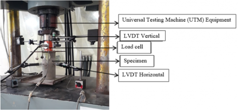
Concrete's compressive strength test is performed in accordance with SNI 1974:2011 [33]. The compressive loading was carried out using a constant displacement speed of 20 mm/min. Two LVDTs were used to measure plate-to-slab displacement, where the vertical strain was obtained by dividing the vertical deformation by the height of the specimen. To obtain lateral strain, three horizontal LVDTs were installed at the center height of the specimen to measure horizontal deformation. Equation 1 displays the equation for the compressive strength test. The compressive strength test of lightweight concrete is depicted in Figure 2.
$\mathrm{f}^{\prime} \mathrm{c}=\frac{\mathrm{P}}{\mathrm{A}}$ (1)
where, f'c=Compressive strength (N/mm2); P=Axial compression force (N); A=Cross-sectional area of the test object (mm2).
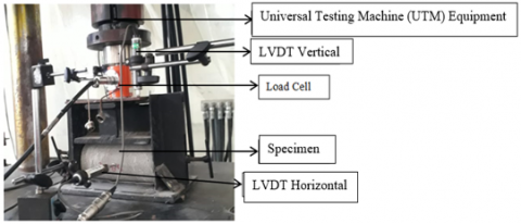
A 100 mm×200 mm cylinder was used to test the indirect tensile strength of lightweight concrete at ages of 3 days, 7 days, and 28 days. The test object is mounted with LVDT on its side to read the vertical deformation due to tensile load. Using a Universal Testing Machine (UTM) with a 1000 kN capacity, the specimens were tested and an LVDT which was connected to a data logger and a set of computers. The split tensile test in this study refers to SNI 03-2491-2012 [34]. Indirect tensile strength is calculated using the equation:
$f^{\prime} c t=\frac{2 \mathrm{P}}{\pi \mathrm{LD}}$ (2)
where, f'ct=Indirect tensile strength (N/mm2); P=Maximum load (N); L=Length of cylindrical test object (mm); D=Diameter of cylindrical test object (mm).
Figure 2. Compressive strength test
Figure 3. Indirect tensile strength test
2.3 Crack pattern after compressive and indirect tensile strength test
Cracks are the type of damage that most often occurs in concrete structures where there is a separation between a relatively long and narrow concrete mass. Visually, the crack looks like a line. Cracks in concrete structures occur before or after the concrete hardens. Cracks will occur when the concrete begins to harden but has been loaded; the concrete hardens in winter due to shrinkage, settlement, and formwork.
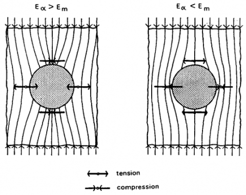
Figure 4 serves as an illustration of the general model of stress distribution in two-phase concrete composites with coarse aggregate particles embedded in a continuous mortar matrix.
Figure 4. When two-phase composites with a spherical inclusion contained in a matrix are subjected to compressive loadings, a general model of the stress distribution is used. Ea is the inclusion's elasticity modulus, while Em is the matrix's elasticity modulus
3.1 Portland composite cement (PCC)
The outcomes of evaluating PCC cement's physical properties are displayed in Table 1. It is clear from Table 1's results that the PCC cement utilized complies with SNI requirements for the necessary concrete materials. The physical qualities of PCC cement were tested. The chemical properties of PCC cement are displayed in Table 2 by XRF-X-ray fluorescence test results. CaO and silica (SiO2), which make up the majority of the cement employed as a binder with percentages of 61.79% and 18.39%, respectively, in its chemical makeup. Whereas MgO, SO3, Al2O3, Fe2O3, and LOI (Loss of Ignation) are the other elements, their respective values are 0.99%, 1.81%, 5.15%, 3.14%, and 4.61%.
Table 1. Physical properties of PCC
|
Inspections |
SNI 15-7064-2004 |
Results of Inspection |
|
Standard |
||
|
Water content (%) |
Max. 12 |
11.5 |
|
Fineness |
Min. 280 |
382 |
|
Expansion, % (max) |
Max. 0.80 |
- |
|
Compressive strength |
|
|
|
a. 3 days (kg/cm2) |
Min. 125 |
185 |
|
b. 7 days (kg/cm2) |
Min. 200 |
263 |
|
c. 28 days (kg/cm2) |
Min. 250 |
410 |
|
Hardening time (Vicat test) |
|
|
|
a. Early hardening, minutes |
Min. 45 |
132.5 |
|
b. Final hardening, minutes |
Min. 375 |
198 |
|
Fake tie time |
Min. 50 |
- |
|
Hydration temperature 7 days, kal/gr |
|
66 |
|
Normal consistency (%) |
|
26.17 |
|
Specific gravity |
|
3.16 |
Table 2. Chemical characteristics of cement (XRF test results)
|
Compound |
Content (%) |
|
MgO |
0.99 |
|
SO3 |
1.81 |
|
SiO2 |
18.39 |
|
Al2O3 |
5.15 |
|
Fe2O3 |
3.14 |
|
CaO |
61.79 |
|
LOI |
4.61 |
3.2 Fine aggregate
The physical parameters of fine aggregate are displayed in Table 3. Silica sand from South Sulawesi's Pinrang Regency is the source of the fine aggregate. The SNI 2417-2019 standard for concrete requirements for structural buildings serves as the foundation for this test.
Table 3. Results of examination of fine aggregate characteristics
|
No. |
Inspections |
Results of Inspection |
|
1 |
Specific gravity a. Dry Specific Gravity b. Saturated Surface Dry Spesific Gravity c. Apparent Spesific Gravity |
2.584 2.608 2.649 |
|
2 |
Water Absorption (%) |
0.911 |
|
3 |
Sludge Content (%) |
0.959 |
|
4 |
Fineness |
1.256 |
|
5 |
Weight Volume (kg/lt) -Loose -Dense |
1.40 1.48 |
|
6 |
Water Content (%) |
3.59 |
|
7 |
Organic Content |
No.1 |
3.3 Research design
In the lab, this research is experimental. With PCC cement, fine aggregate, and foam, lightweight concrete is created in volume variations of 15.7 liters, 25.12 liters, and 37.68 liters. The crack pattern in lightweight concrete formed in a cylindrical mold with a diameter of 100 mm and a height of 200 mm was evaluated at the ages of 3, 7, and 28 days using tests of compressive strength and indirect tensile strength. Table 4 shows the design of the lightweight concrete mix.
Table 4. Design of lightweight concrete mix (1 m3)
|
Material |
Spesific Gravity |
Mixture |
||
|
I |
II |
III |
||
|
Water |
1 |
232 kg |
||
|
Fine Aggregate |
2.48 |
1325 kg |
||
|
Cement |
3.02 |
662.5 kg |
||
|
Admixture (Sikament LN) |
1.22 |
16.6 kg |
||
|
Total |
2236.1 kg |
|||
|
LWC Density (kg/m3) |
1602 |
1470 |
1318 |
|
|
Mortar Portion |
67.47% |
51.13% |
44.59% |
|
|
Foam Portion |
32.53% |
48.87% |
55.41% |
|
|
Ratio Foam Agent/Water |
3: 10 |
|||
3.4 Lightweight concrete casting process
The lightweight concrete casting process is summarized based on the results of the initial mix trial, which did not go through a segregation process and produced a homogeneous lightweight concrete mixture. The steps for mixing lightweight concrete are:
(1) To begin, prepare a foam solution by dissolving the foam agent in a container filled with water in a foam agent to water ratio of 3:1.
(2) The solution is stirred using a propeller for 2 minutes to form a foam. Foaming is done separately in different containers outside the mixer machine.
(3) Then the mortar is made based on the type of casting; Using a mixer, the sand and cement are mixed for two minutes under dry circumstances.
(4) Add the admixture that has been dissolved in water and stir again for 1 minute.
(5) Perform a slump test to ensure that the mixture has reached the desired slump.
(6) When the design slump has been reached, the foamy solution mixture is added to the mortar in the mixer.
(7) Then stir again for 3 minutes until it becomes a lightweight concrete mixture.
(8) After that, check the density of lightweight concrete in a fresh state by taking a number of mixtures in a measuring cup (1000 ml) and then weighing.
(9) Next, pour lightweight concrete 100 mm in diameter and 200 mm in height, into a cylindrical mold.
(10) After 1 day and 24 hours, the specimen is released from the mold for treatment (air curing).
4.1 Compressive and indirect tensile strength
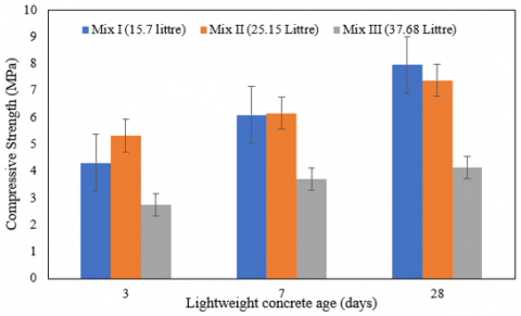
Based on SNI 03-0349-1989, it was found that the strength of lightweight concrete could be used as concrete brick for masonry walls. It is evident that as the age of the lightweight concrete grows, so does the compressive strength value. According to Figure 5, the average compressive strength required for grade IV concrete brick is 2.5 MPa, 9.8 MPa for grade III concrete brick, 6.9 MPa for grade II concrete brick, 9.8 MPa for grade I concrete brick, and 3.9 MPa for grade III concrete brick. For lightweight concrete, mixture I and mixture II can be categorized as quality II concrete. As for the third mix, it is categorized as grade III concrete.
A comparison chart between the value of indirect tensile strength and the age of foam concrete is shown in Figure 6. As can be seen, the split tensile strength values for the first mixture at 3, 7, and 28 days were 0.85 MPa, 0.89 MPa, and 0.91 MPa, respectively. The second mixture had pressures of 0.51 MPa, 0.59 MPa, and 0.78 MPa, while the third mixture had pressures of, respectively, 0.37 MPa, 0.46 MPa, and 0.75 MPa.
Peak stress rises with specimen age in every mixture; this is consistent with the behavior of concrete made with Portland cement. When the concrete matures, the compressive strength of foam concrete keeps rising. The stabilization of bubbles created by the composite Portland cement reaction while mixing foam into concrete, which is subsequently sustained with the hydration process until the age of 28 days, is what leads to an increase in compressive strength. The compressive strength of foam concrete can be impacted by the addition of foam to the mixture.
Figure 5. Comparison diagram between curing age and compressive strength
Based on the test findings, it was determined that the compressive strength value was significantly impacted by the foam agent's addition to the foam concrete mixture. It is clear from the compressive strength figure 5 that the compressive strength diminishes as the volume of foam utilized rises. Concrete examples, both fresh and hard, will be lighter in volume as more foam is added to the mortar mixture. The compressive strength and indirect tensile strength readings will be lower if the concrete test object has a light unit weight.
Figure 6. Comparison diagram between curing age and indirect tensile strength
4.2 Lightweight concrete crack pattern due to compressive and tensile load
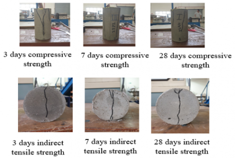
Figure 7 shows the pattern of cracks in foam concrete due to compressive and tensile loads at the ages of 3, 7, and 28 days for mixture I. The crack patterns are the same regardless of the specimen's age, according to the findings of the compressive and split tensile strength tests. The crack pattern can occur due to the spread of stress on the test object due to the tension bonding process of the test object and is affected by the homogeneity of the fine aggregate, PCC cement, and foam agent, which is a constituent of foam concrete. It can be seen that cracks occur between the cement paste in the mortar and the foam that forms cavities or bubbles that occur, this indicates that all test specimens made of sand, PCC cement water and foam agent can blend well so that the test object is able to carry the load. compressive and tensile loads properly. This crack pattern also shows that the fracture width increases as the concrete's age does, and this has a correlation that is proportional to the compressive and tensile strength values produced by the foam concrete test object, which increase with the increase in the age of the concrete.
They also observed that the inner calcium silicate rims around the C, S appear to be strongly bound to the underlying C, S and to be very weakly related to the interstitial material. Hence, they proposed that the unhydrated cement cores serve as "microaggregate" in cement paste. On the other hand, there were no hints of microcracking in the immediate core/hydrate bond. It is believed that in concrete, the aggregate/mortar matrix is where microcracks initially develop before converging into bigger fissures as the fracturing process progresses.
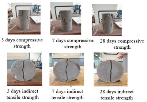
Figure 8 depicts the foam concrete crack pattern under compressive and tensile stresses at 3, 7, and 28 days after mixing mixture II. According to SNI 1974:2011, there are 5 types of concrete cracking patterns, namely, cone destruction, cone destruction and splitting, shear cone destruction, shear destruction, and destruction parallel to the vertical (columnar) axis. Based on the crack pattern that occurs in the test object, it can be concluded that the visually visible crack pattern according to SNI 1974:2011 is destruction parallel to the vertical (columnar) axis. Visually, it can be seen that the paste or mortar made of PCC cement and fine aggregate, as well as the foam agent, crumbled together; this indicates that there is a good bond between the paste or mortar made of PCC cement and fine aggregate (silica sand) and the foam agent. made with a 3:10 ratio with water so that the test object can carry both compressive and tensile loads well.
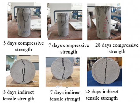
Figure 9 shows the mixed III crack pattern on a cylindrical specimen measuring 10 cm by 20 cm based on the results of the tests for indirect tensile strength and compressive strength. As can be seen, the crack pattern for the compressive strength test is almost identical; it is classified as a columnar crack pattern since it runs parallel to the direction of force. The pattern of cracks that occur decreases with increasing age. From the observations, it can be seen that when split tensile testing is carried out, the mortar and coarse aggregate crack simultaneously. This shows that the concrete is well mixed because cement and water can bind fine aggregates and foam agents that form foam perfectly. Hence, it may be said that as concrete ages, its resistance grows.
Studies have shown that the use of protein-based foaming agents in concrete increases the number of closed-cell bubbles and strengthens the microstructure, resulting in a more stable air-void network in the concrete. One of the most important factors affecting the porosity of foam concrete is the ratio of water to binder (w/b), and the porosity of foam concrete rises as w/b increases. Reduced mix stability and greater separation are the results of using too much foaming agent, which is defined as more than 20% of the volume of the concrete mix.
Figure 7. Mixed I crack pattern of lightweight concrete
Figure 8. Mixed II crack pattern of lightweight concrete
Figure 9. Mixed III crack pattern of lightweight concrete
(1) Sand, PCC cement, and superplasticizer all have high binding qualities, making it possible to combine them to create a mortar that, when combined with foam, produces foam concrete with good compaction. From the age of 3 to 28 days, foam concrete's compressive strength and split tensile strength increased, showing that the bonding process may go smoothly thanks to the good compatibility of all the ingredients utilized.
(2) The compressive strength of foam concrete decreases as the amount of foam utilized increases, producing lighter foam concrete. For masonry walls of class II for the quality level of solid concrete bricks of 70 kg/cm2 and class II for the quality of hollow concrete bricks of 50 kg/cm2, foam concrete with 15.7 liters of foam volume and 25.15 liters of foam volume can be used as concrete bricks. According to SNI 03-0349-1989, foam concrete with a capacity of 37.68 liters can be used as concrete bricks for masonry walls in class III for solid concrete bricks with a quality level of 40 kg/cm2, and in class III for hollow concrete bricks with a quality level of 35 kg/cm2.
(3) As the fracture pattern for the compressive strength test is nearly identical and runs parallel to the direction of the load, it is referred to as a columnar crack pattern. As advancing age, the pattern of cracks that form reduces. Hence, it may be said that as concrete ages, its resistance grows.
This work was supported by the Hasanuddin University Postgraduate school internal grant. The Eco Material and Concrete Laboratory at the Civil Engineering Department of Hasanuddin University, Indonesia, produced and conditioned the lightweight concrete sample. Dr. Muhammad Akbar Caronge, Riswandi, MT, Hasan, ST, and Muhammad Hamdar Yusri, ST, all of whom provided support with this research, are acknowledged by the authors with sincere gratitude.
|
f’c |
Compressive strength (N/mm2) |
|
P |
Axial comprression or tensile force (N) |
|
A |
Cross-sectional area of the test object (mm2) |
|
f’ct |
Indirect tensile strength (N/mm2) |
|
Subscripts |
|
|
SNI |
Standar Nasional Indonesia (Indonesia National Standard) |
|
PCC |
Portland Composite Cement |
|
XRF |
X-ray Fluorescence |
[1] Tumpu, M., Mabui, D.S. (2022). Effect of hydrated lime (Ca (OH) 2) to compressive strength of geopolymer concrete. In AIP Conference Proceedings, 2391(1): 070011. https://doi.org/1063/5.0086702
[2] Mansyur, Tumpu, M. (2022). Compressive strength of normal concrete using local fine aggregate from Binang River in Bombana district, Indonesia. In AIP Conference Proceedings, 2391(1): 070010. https://doi.org/1063/5.0072888
[3] Mansyur, Tumpu, M. (2022). Compressive strength of non-sand concrete with coarse aggregate in Kolaka district as yard pavement. In AIP Conference Proceedings, 2391(1): 070022. https://doi.org/1063/5.0072889
[4] Rangan, P.R., Irmawaty, R., Tjaronge, M.W., Amiruddin, A.A., Bakri, B., Tumpu, M. (2021). The effect of curing on compressive strength of geo-polymer mortar made rice straw ash, fly ash, and laterite soil. In IOP Conference Series: Earth and Environmental Science, 921(1): 012009. https://doi.org/10.1088/1755-1315/921/1/012009
[5] Amiruddin, A.A., Parung, H., Tjaronge, M.W., Tumpu, M. (2021). Utilization of Sea water to production of concrete in terms of mechanical behavior. In IOP Conference Series: Earth and Environmental Science, 921(1): 012068. https://doi.org/10.1088/1755-1315/921/1/012068
[6] Sunarno, Y., Tjaronge, M.W., Irmawaty, R. (2020). Preliminary study on early compressive strength of foam concrete using Ordinary Portland Cement (OPC) and Portland Composite Cement (PCC). In IOP Conference Series: Earth and Environmental Science, 419(1): 012033. https://doi.org/10.1088/1755-1315/419/1/012033
[7] Ramamurthy, K., Nambiar, E.K., Ranjani, G.I.S. (2009). A classification of studies on properties of foam concrete. Cement and Concrete Composites, 31(6): 388-396. https://doi.org/10.1016/j.cemconcomp.2009.04.006
[8] Amiruddin, A.A., Parung, H., Tjaronge, M.W., Irmawaty, R., Tumpu, M. (2022). Influence of prefabricated lightweight concrete as infill wall on the strength due to cyclic loading. International Journal of GEOMATE, 22(93): 114-121. https://doi.org/10.21660/2022.93.j2343
[9] ACI 523.4R-09. (2009). Guide for design and construction with autoclaved aerated concrete panels. Farmington Hills, U.S.A.
[10] Mansyur, M., Tjaronge, M.W., Irmawaty, R., Arwin Amiruddin, A. (2022). Performance of prefabricated foam concrete as infilled wall under cyclic lateral loading. International Journal of Engineering, 35(2): 337-343. https://doi.org/10.5829/ije.2022.35.02b.09
[11] SNI 2847-2019. (2019). Structural Concrete Requirements For Buildings. National Standardization of Indonesia.
[12] Amran, Y.M., Farzadnia, N., Ali, A.A. (2015). Properties and applications of foamed concrete: A review. Construction and Building Materials, 101: 990-1005. https://doi.org/10.1016/j.conbuildmat.2015.10.112
[13] National Standardization. (2002). Indonesian National Standard (SNI) 03-3449-1993. Procedure for Making Plans for Making Lightweight Concrete Mixtures with Light Aggregates. Jakarta: National Standardization Council.
[14] Narayanan, N., Ramamurthy, K. (2000). Structure and properties of aerated concrete: A review. Cement and Concrete Composites, 22(5): 321-329. https://doi.org/10.1016/S0958-9465(00)00016-0
[15] Othuman, M.A., Wang, Y.C. (2011). Elevated-temperature thermal properties of lightweight foamed concrete. Construction and Building Materials, 25(2): 705-716. https://doi.org/10.1016/j.conbuildmat.2010.07.016
[16] Kan, A., Demirboğa, R. (2009). A novel material for lightweight concrete production. Cement and Concrete Composites, 31(7): 489-495. https://doi.org/10.1016/j.cemconcomp.2009.05.002
[17] Koksal, F., Gencel, O., Kaya, M. (2015). Combined effect of silica fume and expanded vermiculite on properties of lightweight mortars at ambient and elevated temperatures. Construction and Building Materials, 88: 175-187. https://doi.org/10.1016/j.conbuildmat.2015.04.021
[18] Hajimohammadi, A., Ngo, T., Mendis, P. (2018). Enhancing the strength of pre-made foams for foam concrete applications. Cement and Concrete Composites, 87: 164-171. https://doi.org/10.1016/j.cemconcomp.2017.12.014
[19] Ranjani, I.S., Ramamurthy, K. (2010). Relative assessment of density and stability of foam produced with four synthetic surfactants. Materials and Structures, 43: 1317-1325. https://doi.org/10.1617/s11527-010-9582-z
[20] Fraj, A.B., Kismi, M., Mounanga, P. (2010). Valorization of coarse rigid polyurethane foam waste in lightweight aggregate concrete. Construction and Building Materials, 24(6): 1069-1077. https://doi.org/10.1016/j.conbuildmat.2009.11.010
[21] Shams, A., Stark, A., Hoogen, F., Hegger, J., Schneider, H. (2015). Innovative sandwich structures made of high performance concrete and foamed polyurethane. Composite Structures, 121: 271-279. https://doi.org/10.1016/j.compstruct.2014.11.026
[22] Benazzouk, A., Douzane, O., Mezreb, K., Quéneudec, M. (2006). Physico-mechanical properties of aerated cement composites containing shredded rubber waste. Cement and Concrete Composites, 28(7): 650-657. https://doi.org/10.1016/j.cemconcomp.2006.05.006
[23] Bing, C., Zhen, W., Ning, L. (2012). Experimental research on properties of high-strength foamed concrete. Journal of Materials in Civil Engineering, 24(1): 113-118. https://doi.org/10.1061/(ASCE)MT.1943-5533.0000353
[24] Jitchaiyaphum, K., Sinsiri, T., Chindaprasirt, P. (2011). Cellular lightweight concrete containing pozzolan materials. Procedia Engineering, 14: 1157-1164. https://doi.org/10.1016/j.proeng.2011.07.145
[25] Panesar, D.K. (2013). Cellular concrete properties and the effect of synthetic and protein foaming agents. Construction and Building Materials, 44: 575-584. https://doi.org/10.1016/j.conbuildmat.2013.03.024
[26] Tikalsky, P.J., Pospisil, J., MacDonald, W. (2004). A method for assessment of the freeze–thaw resistance of preformed foam cellular concrete. Cement and concrete research, 34(5): 889-893. https://doi.org/10.1016/j.cemconres.2003.11.005
[27] Nambiar, E.K., Ramamurthy, K. (2007). Air-void characterisation of foam concrete. Cement and Concrete Research, 37(2): 221-230. https://doi.org/10.1016/j.cemconres.2006.10.009
[28] Kearsley, E.P., Wainwright, P.J. (2001). The effect of high fly ash content on the compressive strength of foamed concrete. Cement and Concrete Research, 31(1): 105-112. https://doi.org/10.1016/S0008-8846(00)00430-0
[29] Sang, G., Zhu, Y., Yang, G., Zhang, H. (2015). Preparation and characterization of high porosity cement-based foam material. Construction and Building Materials, 91: 133-137. https://doi.org/10.1016/j.conbuildmat.2015.05.032
[30] Amran, Y.M., Farzadnia, N., Ali, A.A. (2015). Properties and applications of foamed concrete; a review. Construction and Building Materials, 101: 990-1005. https://doi.org/10.1016/j.conbuildmat.2015.10.112
[31] Neville, A. (1995). Chloride attack of reinforced concrete: an overview. Materials and Structures, 28: 63-70.
[32] Jones, M.R., McCarthy, M.J., McCarthy, A. (2003). Moving fly ash utilisation in concrete forward: A UK perspective. In Proceedings of the 2003 International Ash Utilization Symposium, Lexington, KY, USA: University Press of Kentucky, pp. 20-22.
[33] Indonesian National Standard. SNI 1974. (2011). Test Method for Compressive Strength of Concrete with Cylindrical Test Objects. National Standardization of Indonesia.
[34] Indonesian National Standard. SNI 03-2491. (2012). Split Tensile Strength Test Method for Cylindrical Concrete Specimens. National Standardization of Indonesia.