Souad Zergot* | Mustafa Moussaoui | Brahim Elkhalil Hachi
© 2022 IIETA. This article is published by IIETA and is licensed under the CC BY 4.0 license (http://creativecommons.org/licenses/by/4.0/).
OPEN ACCESS
The crack initiation and propagation often occur in structures subjected to fatigue loads and their privileged sites it is the geometric discontinuity in particular the notches. The geometric configuration of the notches always leads to disturbances of stress fields in the vicinity of the notch end as a consequence of the effects on the crack initiation site and on the crack rate. The present study is interested to the evolution of crack speed propagation in the notched specimens subjected to bending. The specimens chosen are made of PMMA material containing two opposite notches U or V that presented two different parameters, a radius for U-notch and angle for V-notch. The variations taken into account for the sharp notches (V-notch) going from the small angle to the large angle, which are 30°; 45°, 90°, and 140°, and for blunt notches (U-notch) the radius takes the different values 0.5, 1, 1.5, and 2 mm. The fracture brittle behavior adapted to this material led to predict the Fatigue crack growth using a modified form of Paris’s law with the equivalent stress intensity factor ($\Delta$Keq) relying on extended finite element method (XFEM) in order to follow the interaction between the notch and the crack on one side and study the evolution of crack growth rate to another side. The variations, which brought to these parameters entailed an influence on the crack propagation speed, which was born at the end of notch of component as well as the variations of equivalent notch intensity stress factors ($\Delta$Keq). The variations made to the parameters of notches have a huge influence on the crack propagation rate.
XFEM method, equivalent notch stress intensity factor, fatigue crack growth rate, polymethyl methacrylate, notch
The process of fatigue crack growth (FCG) near geometric discontinuities is complicated and may be due to several factors such as loading conditions, material composition and geometry of the defects. Many geometric shapes designed by design necessity in mechanical parts are considered geometric discontinuity such as grooves, holes, shoulders. Notches are among the geometric discontinuities, which can produce local stress concentration or strain concentration phenomenon locally, therefore, it is important to simulate the propagation of fatigue cracks and make predict of life cycles before the destructive fracture occurs.
The propagation mechanism of notched structural components subjected to cyclic load consists of two phases: fatigue crack initiation and propagation. The privileged place of initiation is the geometrical modification in particular the notch is generally considered the site, which can acquire the initiation of cracks and tend to its propagation. In theory, the use of linear elastic fracture mechanics concepts has been proved with considerable success in interpreting fatigue crack growth data. Many propagation rate laws have been proposed, including polynomial [1], exponential [2], power functions [3]. One of the most widely accepted in the Paris-Erdogan [4] fatigue crack growth law is:
$\frac{d a}{d N}=C \Delta K^{m}$ (1)
where, a is crack length, N is the number of cycles, $\Delta$K equal (Kmax-Kmin) and C and m are material constants, Kmax is maximum stress intensity factor, Kmin is minimum stress intensity factor.
Several factors can affect the crack propagation behavior in the stressed region such as the crack length (for the short crack propagation regime), the grain size, the stress ratio (R) and the environment, e.g., air humidity [5]. In the notches, other parameters can intervene in cracks propagation, these parameters are related to the geometric configuration of notch, which is the length, the radius and the opening angle. The relationship between initiation, propagation, the size and shape of holes and notches must be correctly understood for correct understanding of the notch effect phenomenon. Crack initiation is localized at high stress concentration sites that generally appear at the notch bottom. A popular belief is that unavoidable defects caused by the manufacturing process act as direct triggers for fatigue crack propagation and that the fatigue crack initiation period can be neglected.
In recent years, extensive studies have been focused to investigate the behavior of fatigue crack propagation in specimens containing a notch. Dong et al. has been worked in estimate total fatigue lives for crack initiation and propagation of notched plates [6]. They proposed an approach with two phases. The proposed approach is applied to predict fatigue live of various notched specimens. The used approach is based on the strain life curve, considering the stress gradient and microstructure effects, for the most severe conditions where the notch radius is in the order of 10 μm, approximate 15% fatigue life is spent in the initiation phase. Gadallah et al. [7] investigated the effect of thickness and stress level on fatigue crack growth FCG behavior for mild steel in notched specimens. Their results showed that thickness has a remarkable effect on the crack growth rate at the free surface when the applied stress level is below and close to the general yield where the thinner specimens gave faster crack growth rates. The crack-tip driving force $\Delta J$ has a noticeable contribution to controlling the behavior of crack growth.
The mechanism of fatigue crack propagation was analyzed by molecular dynamics (MD) with the Paris law model by Cheng et al. [8]. They analyzed the effect of microstructural defects on the propagation of fatigue cracks. They used a carbon steel plate atomic model at the microscopic scale, applied to a representative volume element-RVE. research was conducted by Kravchenko et al. [9] used a two-parameter model on the local state of stress at the crack tip to study the effect of local stress state at the crack tip on the fatigue crack propagation rate (FCPR) on PMMA material. It was shown that in the case of high cycle fatigue, the crack propagation rate cannot be adequately characterized by the apparent change in the stress intensity field at the crack tip alone, a second parameter must be added to the K-stress, which represents the non-singular stress near the crack tip. It has been noted that variable shapes and sizes of laboratory samples may produce essentially different local states of stress at the crack fronts when the stress intensity alone can no longer accurately represent the crack driving force [10, 11].
In the study of Castro et al. [12] who wanted to consider the parameter effective stress intensity factor $\Delta$ Keff as a driving force in the FCG, assuming that Elber's effective stress intensity factor as the fatigue crack driving force so it can be used to explain all load sequence effects fatigue crack growth (FCG). With the application of two approaches: Critical Distances and total Strain Energy Density, Brancoa et al. [13] was studied the Fatigue crack behavior of notched 34CrNiMo6 high-strength steel bars with transverse blind holes and lateral U-shaped notches subjected to proportional bending-torsion loading. From the maximum value of the first principal stress, they could determine Crack initiation sites, crack surface angles and surface crack paths at the geometric discontinuities. Fageehi and Alshoaibi [14] analyzed the fatigue crack propagation under mixed-mode loading for two different loading angles of 30° and 60°. The predicted values of $\Delta$ Keq showed consistency with the results achieved with similar models of predicting the equivalent stress intensity factor and the outcomes of the direction of crack growth obtained was followed the same trend of the literature.
To describe the phenomenon of fatigue and the propagation, an interest is focused on the constant of the Paris law cited in the works of Balfon et al. [15] who they proposed an empirical relation linking the two constant m and C of Paris for three types of aluminum alloys 2024-T3, 2618A-T651 and 7175-T7351. A double-U specimen of a new generation nickel base super alloy was used to obtain experimental crack shapes within the transitory region and the number of load cycles between them. This specimen was developed to reproduce the geometry of a turbine disc at the region of its connection with the blades, since this is a high stress concentration zone prone to fatigue failures. Central hole-notched specimens were analyzed using a fracture mechanics approach the obtained curves (da/dN-K) indicate that Ultra-Quartz has the lowest fatigue crack growth rate while Asterite has the worst resistance to crack growth, but still has a crack propagation rate of about two orders of magnitude below the PMMA [16]. In fact, the addition of filler particles significantly increases the fatigue crack growth resistance of these materials relative to the PMMA matrix. A study of the propagation of fatigue cracks in center-notched sheets of polymethylmethacrylate under cyclic tension conditions made by Radon et al. [17], in order to study effects of the mean stress intensity factor, Kmean, and the range of stress intensity factor, $\Delta K$ on crack propagation phenomena where they concluded that the existing inconsistencies between the stress intensity factor AK and its mean value, can be avoided by describing the crack growth rate in terms of a parameter $\left(K_{\max }^{2}-K_{\min }^{2}\right)$. The work of Bi̇li̇r [18] is interested in the propagation of cracks of SAE 1010 steel of sheet specimens containing elliptical holes. It is concluded from this study that there is a linear correlation between the parameters of pars ’law m and log C.
Many propagation rate laws have been proposed, and the phenomenon of crack propagation has been studied in many studies. But this study provides useful information about the role of notch geometry on the speed of crack propagation and the equivalent notch stress intensity factor for polymethyl methacrylate materials. That’s why we were interested in studying the effects generated by the presence of notches in a structure on fatigue crack propagation rate and also to determine the influence of the notch stress intensity factor on crack propagation. The existing varieties of notch geometries play an important role in localizing crack initiation and its propagation rate. We can cite that sharp notch develop higher speeds compared to blunt notches, and which will have an impact on the life of the mechanical components.
This study is essentially based on a numerical analysis and validated with the theoretical law using the equivalent notch stress-intensity-factor concept from fracture mechanics theory.
This paper is organized as follows. Section 1 is an introduction to some previous studies. Section 2 describes the theoretical background and is divided into three subsections: 2.1 classical crack propagation laws in fatigue. 2.2 notch stress intensity factors expression and 2.3 fatigue crack propagation modeling. Section 3 describes mechanical properties and specimens’ geometry. Section 4 provides the numerical analysis and results were in the subsection 4.1 we present the results of effect of V-notch on fatigue crack propagation and the results of effect of U-notch on fatigue crack propagation in 4.2. Subsection 4.3 shows the results of the equivalent notch stress intensity factors as a function of crack propagation length for acute notches (V-notch) and blunt notches (U-notch). Section 5 summarizes the results that show the effect of geometric parameters on crack propagation and the equivalent notch stress intensity factor as well as the effect of notched shape and opening angle on speed of crack propagation velocity.
2.1 Classical crack propagation laws in fatigue
The law proposed by Paris does not describe the entire curve; however, other empirical or analytical laws have been proposed to describe the entire propagation curve [19-21]. Forman [19], to take into account the asymptotic increase in cracking rate when $K_{I c}-K_{\max }$, proposed an improvement of the Paris relation to describe do mains II and III of the propagation curve:
$\frac{d a}{d N}=\frac{C \Delta K^{m}}{(1-R)\left(K_{I c}-K_{\max }\right)}$ (2)
where, C and m are a constant depending on the material, for steels m is of the order of 4. This relation does not take into account the existence of a cracking threshold but involves the influence of the load ratio R on the cracking rate.
To account for the threshold effect in region I, Klesnil and Lucas [20] proposed a modification of the relation in the form:
$\frac{d a}{d N}=C\left(\Delta K^{m}-\Delta K_{\text {threshold }}^{m}\right)$ (3)
Frost then proposed a relation which accounts for the entire propagation curve, established for ferritic-pearlitic steels [21]:
$\frac{d a}{d N}=B\left[\frac{\left(\Delta K-\Delta K_{\text {threshold }}\right)^{4}}{\left(R_{m}^{2}\right)\left(K_{I c}^{2}-K_{\max }^{2}\right)} \quad \right]^{n}$ (4)
KIc designating the critical value of the stress intensity factor, Kthreshold is the value of K at the propagation threshold for a given load ratio R, Rm is the tensile strength of the material, B and n are constant characteristic of the material.
A formulation of crack propagation relating the rate of strain energy release ($\Delta$G) to the speed of propagation described by Woo and Chow [22]. This implies that the range, ($G_{C}-G_{\max }$) has a definite effect on the mean stress (or R) defined as the ratio $K_{\max }$ and $\mathrm{K}_{\min }$ because of its dependence on the applied of load.
$\frac{d a}{d N}=A_{1} \frac{(\Delta G)^{m_{1}}}{G_{c}-G_{m a x}}$ (5)
where, A1 and m1 are material constants.
2.2 Notch stress intensity factors expression
The stress distribution at notches can be described by the loading mode related notch stress intensity factor - NSIF K1r as the governing field parameters. In fatigue the notch is associated with a crack propagation which is initiated at the tip notch for V -notch but for U-notch for certain radius, the crack is initiated from an offset point compared to the tip notch.
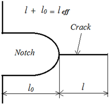
For evaluating the notch stress intensity factor in the case of a crack emanating from a notch, the length considered as a discontinuity in the specimen becomes an effective length $\left(l_{e f f}=l_{0}+l\right)$ (Figure 1) which includes the length of the notch added to the length of the crack develop after propagation for elastic stress intensity factor is proposed in References [23-25]. The expression is below:
Figure 1. Notch with crack at its end
$\Delta K=\beta \sigma_{t i p} \sqrt{\pi\left(l_{e f f}\right)}$ (6)
where, $\beta$ is geometrical coefficient, $\sigma_{t i p}$ maximal stress at the notch tip.
In this test, the specimen is subjected to a mixed mode I and II due to a deviation of crack by a low angle in which mode I appears a predominant mode with higher values compared to mode-II, the stress intensity factor used is the equivalent notch stress intensity factor described by Irwin et al. [26, 27].
$\Delta K_{e q}=\sqrt{\Delta K_{I}^{2}+\Delta K_{I I}^{2}}$ (7)
In mode I the analytical expression of $\Delta K_{I}$ is by the following relation:
$\Delta K_{I}=\beta \sigma_{x x} \sqrt{\pi\left(l_{e f f}\right)}$ (8)
And the relation which gives the stress intensity factor in mode II, $\Delta K_{I I}$ will therefore be:
$\Delta K_{I I}=\beta \sigma_{x y} \sqrt{\pi\left(l_{e f f}\right)}$ (9)
2.3 Fatigue crack propagation modeling
When we analyzed the crack propagation by Eq. (1) applied to polymeric materials, which includes PMMA, polycarbonate and nylon 66, no satisfaction was obtained in terms of results as indicated by Arad et al. [28]. Sutton [29] used the formulation proposed by Arad et al. [28, 30], where they applied some modifications for propagating fatigue cracks in polymers in terms of strain energy release rate $\Delta$G, such as:
$\frac{d a}{d N}=A_{3} \Delta G^{m_{3}}$ (10)
The basic reason for the success of (10) is due to its inherent capability of the strain energy release rate $\Delta$G taking into account the effect of mean stress intensity as:
$\Delta G=2 \Delta K K_{\text {mean }} / E^{\prime}$
$E^{\prime}=E$ (Plane stress), $E^{\prime}=\frac{E}{1-v^{2}}$ (Plane strain) (11)
where, E is the modulus of elasticity and v is poisson’s coefficient.
The prediction of the fatigue cracks propagation using the equivalent NSIF$\left(\Delta K_{e q}\right)$ is an approach described by Tanaka [31] under cyclic loading of mixed mode I/II where, he proposed a power law in the modified form of Paris’s law. Based on Tanaka's idea, we opted for Eq. (11) as the model used in determining the fatigue life prediction and quantifying the propagation velocity in PMMA.
From the Eq. (11) used as analytical, the term of equivalent notch stress intensity factor (8) was substituted in Eq. (12).
$\frac{d a}{d N}=A_{3}\left[\frac{2 \Delta K_{e q} K_{\text {mean }}}{E^{\prime}}\right]^{m_{3}}$ (12)
The analytical relation of fatigue crack propagation which will be able to use becomes:
$\frac{d a}{d N}=A_{3}\left[\left(2 K_{\text {mean }} \Delta K_{e q}\right) / E^{\prime}\right]^{m_{3}}$ (13)
with:
$\Delta K_{e q}=\left[\sqrt{\left(\beta \sigma_{x x} \sqrt{\pi\left(l_{e f f}\right)}\right)^{2}+\left(\beta \sigma_{x y} \sqrt{\pi\left(l_{e f f}\right)}\right)^{2}}\right]$ (14)
The material chosen for this study is polymethylmethacrylate (PMMA) because it is a relatively homogeneous isotropic medium which exhibits brittle fracture and almost linear elastic behavior and these mechanical properties are shown in the Table 1.
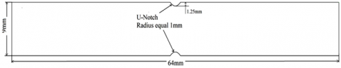
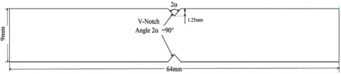
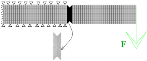
The interested finite element model is a plate containing two opposite notches, which can either a V notch or a U notch, the V notches have as variable the opening angle (30°, 45°, 90° and 140°) while the U-notches is considered the radius as a variable (0.5,1,1.5 and 2mm). The finite element model is subjected at its end by a cyclic loading of amplitude 50 N, the second end is embedded; this leads to a simple bending stress. The system considered is animated by bending fatigue, producing disturbances of the stress and strain fields at the notch tip. The simulation is carried out in Cast3m calculation code with a mesh in element with four nodes Q4 (Figure 2c).
At the level of the groove where the notches are located, mesh refining is carried out in order to bring precision to the results. The dimensions of the specimen are shown in Figure 2a and 2b.
The method adopted in this work is based on the extended finite element method (XFEM). The latter is known by its capacity to follow the propagation of crack without recourse to structural remising by addition of the enrichment of nodes which receive the crack, it provides to the equation of displacements of the terms allows it to increase the number of degrees of freedom (DOF). The enriched approximation for a single interface Γd can be written as:
$u(x)=u^{F E M}+u^{E n r}=\sum_{i=1}^{N} N_{i}(x) \bar{u}_{i}+\sum_{j=1}^{M} N_{j}(x) \psi(x) \bar{a}_{j}$ (15)
in which the shape functions of enriched part are chosen similar to the FE shape functions Ni(x). $\bar{u}_{i}$ is the standard nodal displacement, $\bar{a}_{j}$ is the nodal DOF corresponding to the enrichment function, $\psi(x)$ is the enrichment function, and N(x) is the standard shape function. $\mathcal{N}$ is the set of all nodal points of domain, and $\mathcal{M}$ is the set of nodes of elements located on the discontinuity $\Gamma_{d}$.
Table 1. Mechanical properties of PMMA
|
Ultimate Tensile Strength [MPa] |
Ultimate flexural strength [Mpa] |
Ultimate Compression Strength [MPa] |
Elastic Modulus E [MPa] |
Poisson's Ratio n |
Density (kg/m3) |
Fracture toughness [MPa m0.5] |
|
70.5 |
110 |
117 |
3000 |
0.4 |
1190 |
1.96 |
Figure 2a. Double-U specimen (dimensions in mm)
Figure 2b. Double-V specimen (dimensions in mm)
Figure 2c. Finite element model with V-Notch
It is well known that the fatigue damage of components subjected to normally elastic stress fluctuations occurs at regions of stress raisers where the localized stress exceeds the yield stress of the material. After a certain number of load fluctuations, the accumulated damage causes the initiation and subsequent propagation of a crack, or cracks, in damaged regions. This process can and in many cases does cause the fracture of components. The more severe the stress concentration, the shorter the time to initiate a fatigue crack. Some parts or structures present defect plans in the gross state of manufacture or cracks initiated in services from defects or stress concentration zone. The determination of the service life of such elements requires the knowledge of the crack propagation speed according to the loading conditions.
The propagation of a fatigue crack appears when the variation $\Delta K$ during a loading cycle is greater than the propagation threshold $\Delta K_s$. This propagation is limited by the sudden rupture of the part when the notch stress intensity factor (NSIF) reaches a greater value than KIc, between these two extremes, there is a domain of propagation expressed by a linear relation between the logarithm of the propagation speed and the logarithm of the stress intensity factor variation. This domain which is represented by Paris’s law indicated by the relation (1), some authors have contributed to modifications of this law to take into account the two regions of (da/dN-$\Delta K$) curve, and the application of these modified formulas to the different materials have made it possible to bring about an approval with the results obtained by the experimental by a similarity better than that of Paris’s relation. However, Sutton [29] found that the relation (10) is more adequate for PMMA materials and polymers. From this, we numerically analyzed the specimen behavior by this relation and looking for the geometry effect of the notches on speed propagation.
The constants used in Eq. (10) for PMMA material are shown in Table 2.
Table 2. Material constants
|
A1 |
m1 |
|
3.611E-4 |
1.076 |
4.1 Effect of V-notch on fatigue crack propagation
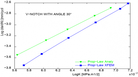
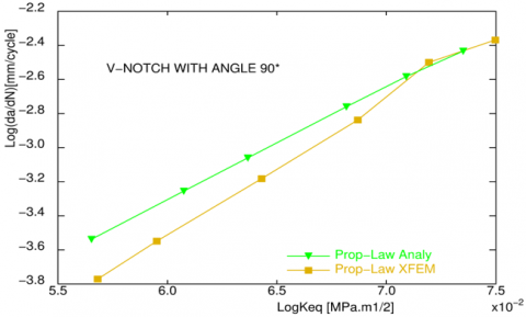
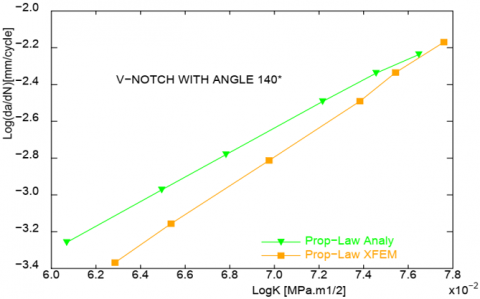
Figure 3. Fatigue crack growth rate versus $\Delta$Keq data of PMMA for V-notch
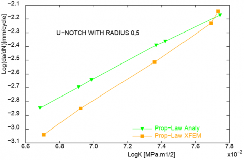
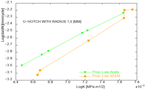
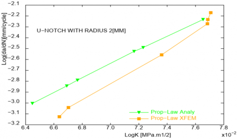
Figure 4. Fatigue crack growth rate versus $\Delta$Keq data of PMMA for U-notch
During bending loading of the specimen, disturbances of the stress and strain fields near the end of the notch with significant amplification at the bottom of the notch.
The cyclic loading leads to localized crack initiation in the place, where the principal stress $\sigma_{\mathrm{xx}}$ reaches the maximum value. This principal stress criterion is used in our simulation to define the initiation point of crack, which generally starts from the notch tip, where there is a high stress concentration. The appearance of the crack at the notch produces an interaction between the crack and the notch. In the Figures 3 shows logarithmic curves between (da/dN) values and the stress intensity factor for each notch opening angle, a comparison of the results obtained with those of the analytical expression. By increasing the opening angle, the propagation speed decreases while the variation of the stress intensity factor increases.
We estimate from the curves that for the angle 140°, the propagation is slow at the start (2.2mm / cycle) of the first propagation compared to the low angles (angle 30°, 2.6mm / cycle). With the comparison the results obtained using the XFEM method are close to the analytical values.
4.2 Effect of U- Notch on fatigue crack propagation
For blunt notches, Figures 4 shows the evolution of (da/dN) as a function of stress intensity factors. The geometry of the notches which have à radius different from zero reduces the amplitude of the stresses which reign near the bottom of the notch and the zone in the vicinity of the bottom of the notch becomes less stressed, this will have an influence on the rate of propagation of the crack. The location of the crack initiation in the geometry of the blunt notch is initiated at the point which is offset from the notch bottom on the contour of the notch crescent this is shown by several authors [32-34]. The different radii 0.5, 1, 1.5 and 2mm are chosen in such a way to create the space of difference in the crack propagation rate and on the fracture parameter $\Delta$Keq between the radii.
The finding that can be discerned with blunt notches is that the speed of crack propagation is slow compared to acute notches type V, the variation in radius causes variation in the crack propagation.
As the radius increases, the speed of crack propagation and equivalent notch stress intensity factor values increase. Low propagation rates are associated with higher stress intensity factor values. In terms of results obtained analytically converge toward the results XFEM.
4.3 Effect of equivalent notch stress intensity factor on fatigue crack propagation
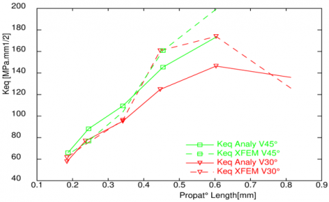
Figure 5. Comparison of equivalent notch stress intensity factors-($\Delta$Keq), between analytical and xfem-method for V-notch
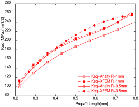
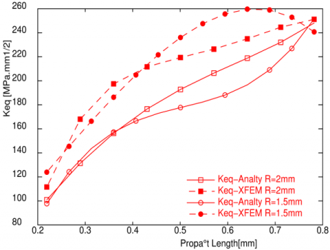
Figure 6. Comparison of equivalent notch stress intensity factors-($\Delta$Keq) between analytical and xfem-method for U-notch
Figures 5 and 6 show a representation of the evolution of the equivalent notch stress intensity factors as a function of crack propagation length for acute notches (V-notch) and blunt notches (U-notch). The growth of the crack that appears at the notch end leads to an increase in the equivalent notch stress intensity factor (ENSIF) at the same time, the high opening angles also lead to the growth of the values of equivalent notch stress intensity ($\Delta$Keq). The curve of notch V140° indicates greater values compared to small opening angles (Figure 5). In Figures 6, a polynomial interpolation is applied for the blunt notches to have curve smoothing. The results obtained show that the small radii and the extension of the crack length will increase the equivalent notch stress intensity factors ($\Delta$Keq). The confrontation between the numerical and the analytical results shows an acceptable agreement.
The present work conducted a study on the role of notch geometries on the crack propagation speed and on the brittle fracture parameter for the polymethyl methacrylate material. Two types of notches commonly used in research and which have differences in their geometry and in their geometric parameters. The presence of notches in the mechanical parts will cause disturbances in the stress field generated by the concentration of the stresses in particular in the zone surrounding the end and which consequently affects the initiation and the speed of propagation of cracks. We considered the blunt and sharp notches, their geometrical parameters taken into account are the variation of radius for “U- notch” and the angle for “V- notch”.
Through this study, we analyzed the fatigue crack propagation rate of specimens containing notches by the modified law described by SUTTON [29] of PMMA material using the extended finite element method.
The change of notch type (U or V) allowed to modify the evolution of the crack propagation. The presence of notches in a structure generates stress field disturbances therefore fluctuations will affect the estimation of equivalent notch stress intensity factors ($\Delta$Keq). The variations that are adopted in the geometric parameters influence the speed of crack propagation and the equivalent notch stress intensity factor.
In the case where the equivalent notch opening angle is large, the crack propagation becomes slow and the notch stress intensity factor tends toward higher intensities.
The initiation of cracks appears at the notch tip where the stress concentration is high, described by the criterion of the maximum principal stress.
In the U-shaped notches, the high radii cause a variation in the crack propagation.
Increasing radius results in increasing propagation velocity and stress intensity factor values. The propagation speed of the U-notch is slow compared to sharp notches (type V).
The results found show that the variance in the fracture toughness of the materials is mainly due to the changes found in the grain structure of the materials [35]. The results obtained during the experiments have shown that, the fracture behavior of the coated and heat-treated aluminum a material is changed significantly.
In the next step, it is important to expand the study on notch geometry on the speed of crack propagation, for example notches with sharp and blunt notch with some (U, V), also the effect of crack depth in controlling speed of crack propagation for polymethyl methacrylate materials.
[1] Davies, K.B., Feddersen, C.E. (1973). Evaluation of fatigue-crack growth rates by polynomial curve fitting. International Journal of Fracture, 9(1): 116-118. https://doi.org/10.1007/BF00035965
[2] Frost, N.E., Dugdale, D.S. (1958). The propagation of fatigue cracks in sheet specimens. Journal of the Mechanics and Physics of Solids, 6(2): 92-110. https://doi.org/10.1016/0022-5096(58)90018-8
[3] De Iorio, A., Grasso, M., Penta, F., Pucillo, G.P. (2012). A three-parameter model for fatigue crack growth data analysis. Frattura ed Integrità Strutturale, 6(21): 21-29. https://doi.org/10.3221/IGF-ESIS.21.03
[4] Paris, P., Erdogan, F. (1963). A critical analysis of crack propagation laws. Journal of Fluids Engineering, 85(4): 528-533. https://doi.org/10.1115/1.3656900
[5] Zerbst, U., Vormwald, M., Pippan, R., Gänser, H.P., Sarrazin-Baudoux, C., Madia, M. (2016). About the fatigue crack propagation threshold of metals as a design criterion–a review. Engineering Fracture Mechanics, 153: 190-243. https://doi.org/10.1016/j.engfracmech.2015.12.002
[6] Dong, Y., Garbatov, Y., Soares, C.G. (2018). A two-phase approach to estimate fatigue crack initiation and propagation lives of notched structural components. International Journal of Fatigue, 116: 523-534. https://doi.org/10.1016/j.ijfatigue.2018.06.049
[7] Gadallah, R., Murakawa, H., Ikushima, K., Shibahara, M., Tsutsumi, S. (2021). Numerical investigation on the effect of thickness and stress level on fatigue crack growth in notched specimens. Theoretical and Applied Fracture Mechanics, 116: 103138. https://doi.org/10.1016/j.tafmec.2021.103138
[8] Cheng, Z., Wang, H., Liu, G.R. (2021). Fatigue crack propagation in carbon steel using RVE based model. Engineering Fracture Mechanics, 258: 108050. https://doi.org/10.1016/j.engfracmech.2021.108050
[9] Kravchenko, S.G., Kravchenko, O.G., Sun, C.T. (2014). A two-parameter fracture mechanics model for fatigue crack growth in brittle materials. Engineering Fracture Mechanics, 119: 132-147. https://doi.org/10.1016/j.engfracmech.2014.02.018
[10] Rhodes, D., Radon, J.C. (1983). Effect of some secondary test variables on fatigue crack growth. ASTM STP, 791: 33-16.
[11] Vecchio, R.S., Crompton, J.S., Hertzberg, R.W. (1987). The influence of specimen geometry on near threshold fatigue crack growth. Fatigue & Fracture of Engineering Materials & Structures, 10(4): 333-342. https://doi.org/10.1111/j.1460-2695.1987.tb00211.x
[12] Castro, J.T.P., Meggiolaro, M.A., González, J.A.O. (2015). Can Delta Keff be assumed as the driving force for fatigue crack growth? Frattura ed Integrità Strutturale, 9(33): 97-104. https://doi.org/10.3221/IGF-ESIS.33.13
[13] Branco, R., Costa, J.D., Berto, F., Kotousov, A., Antunes, F.V. (2020). Fatigue crack initiation behaviour of notched 34CrNiMo6 steel bars under proportional bending-torsion loading. International Journal of Fatigue, 130: 105268. https://doi.org/10.1016/j.ijfatigue.2019.105268
[14] Fageehi, Y.A., Alshoaibi, A.M. (2020). Numerical simulation of mixed-mode fatigue crack growth for compact tension shear specimen. Advances in Materials Science and Engineering, 2020: 5426831. https://doi.org/10.1155/2020/5426831
[15] Baflon, J.P., Masounave, J., Bathias, C. (1977). On the relationship between the parameters of Paris' law for fatigue crack growth in aluminium alloys. Scripta Metallurgica, 11(12): 1101-1106. https://doi.org/10.1016/0036-9748(77)90315-5
[16] Antunes, F.V., Ferreira, J.M., Costa, J.D., Capela, C. (2002). Fatigue life predictions in polymer particle composites. International Journal of Fatigue, 24(10): 1095-1105. https://doi.org/10.1016/S0142-1123(02)00016-6
[17] Radon, J.C., Arad, S., Culver, L.E. (1974). Growth of fatigue cracks in metals and polymers. Engineering Fracture Mechanics, 6(1): 195-208. https://doi.org/10.1016/0013-7944(74)90057-5
[18] Bi̇li̇r, Ö.G. (1990). The relationship between the parameters C and n of Paris' law for fatigue crack growth in a SAE 1010 steel. Engineering Fracture Mechanics, 36(2): 361-364. https://doi.org/10.1016/0013-7944(90)90015-9
[19] Forman, R.G. (1972). Study of fatigue crack initiation from flaws using fracture mechanics theory. Engineering Fracture Mechanics, 4(2): 333-345. https://doi.org/10.1016/0013-7944(72)90048-3
[20] Klesnil, M., Lukáš, P. (1972). Influence of strength and stress history on growth and stabilisation of fatigue cracks. Engineering Fracture Mechanics, 4(1): 77-92. https://doi.org/10.1016/0013-7944(72)90078-1
[21] Frost, N.E., Pook, L.P., Denton, K. (1971). A fracture mechanics analysis of fatigue crack growth data for various materials. Engineering Fracture Mechanics, 3(2): 109-126. https://doi.org/10.1016/0013-7944(71)90003-8
[22] Woo, C.W., Chow, C.L. (1984). Fatigue crack propagation in aluminium and PMMA. International Journal of Fracture, 26(2): R37-R42. https://doi.org/10.1007/BF01157551
[23] El Haddad, M.H., Smith, K.N., Topper, T.H. (1979). Fatigue crack propagation of short cracks. Journal of Engineering Materials and Technology, 101(1): 42-46. https://doi.org/10.1115/1.3443647
[24] Radaj, D., Vormwald, M. (2013). Advanced Methods of Fatigue Assessment (pp. 101-265). Berlin/Heidelberg, Germany: Springer.
[25] Broek, D. (2012). The Practical Use of Fracture Mechanics. Springer Science & Business Media.
[26] Irwin, G.R. (1957). Analysis of stresses and strains near the end of a crack traversing a plate. Journal of Applied Mechanics, 24(3): 361-364. https://doi.org/10.1115/1.4011547
[27] Sajith, S., Murthy, K.S.R.K., Robi, P.S. (2018). Fatigue life prediction under mixed-mode loading using equivalent stress intensity factor models. MATEC Web of Conferences, 172: 03005. https://doi.org/10.1051/matecconf/201817203005
[28] Arad, S., Radon, J.C., Culver, L.E. (1971). Fatigue crack propagation in polymethylmethacrylate; the effect of the mean value of stress intensity factor. Journal of Mechanical Engineering Science, 13(2): 75-81. https://doi.org/10.1243%2FJMES_JOUR_1971_013_013_02
[29] Sutton, S.A. (1974). Fatigue crack propagation in an epoxy polymer. Engineering Fracture Mechanics, 6(3): 587-595. https://doi.org/10.1016/0013-7944(74)90015-0
[30] Arad, S., Radon, J.C., Culver, L.E. (1972). Design against fatigue failure in thermoplastic. Engineering Fracture Mechanics, 4(3): 511-522. https://doi.org/10.1016/0013-7944(72)90062-8
[31] Tanaka, K. (1974). Fatigue crack propagation from a crack inclined to the cyclic tensile axis. Engineering Fracture Mechanics, 6(3): 493-507. https://doi.org/10.1016/0013-7944(74)90007-1
[32] Berto, F., Ayatollahi, M.R. (2017). A review of the local strain energy density approach applied to V-notches. Физическая Мезомеханика, 20(2): 14-27.
[33] Torabi, A.R., Campagnolo, A., Berto, F. (2015). Local strain energy density to predict mode II brittle fracture in Brazilian disk specimens weakened by V-notches with end holes. Materials & Design, 69: 22-29. https://doi.org/10.1016/j.matdes.2014.12.037
[34] Berto, F., Lazzarin, P. (2009). The volume-based Strain Energy Density approach applied to static and fatigue strength assessments of notched and welded structures. Procedia Engineering, 1(1): 155-158. https://doi.org/10.1016/j.proeng.2009.06.036
[35] Manjunath, R., Kumar, D. (2020). Effects of aging temperature, time during transition from brittle to ductile on fracture behavior of zinc coated AA7075. Annales de Chimie - Science des Matériaux, 44(3): 211-216. https://doi.org/10.18280/acsm.440308