Ihor Kliushnikov* | Herman Fesenko | Vyacheslav Kharchenko | Oleg Illiashenko | Olga Morozova
© 2021 IIETA. This article is published by IIETA and is licensed under the CC BY 4.0 license (http://creativecommons.org/licenses/by/4.0/).
OPEN ACCESS
The existing approaches suggest that justifying robotic monitoring systems composition and use planning are carried out through a set of predefined missions. The paper proposes the algorithm of justifying composition and utilization of monitoring systems for critical infrastructure objects based on the theory of transport systems considering possible types of the monitoring missions. The considered monitoring system comprises a fleet of unmanned aerial vehicles (UAV fleet) and automatic battery replacement systems. The algorithm provides a procedure for defining the monitoring system composition and using the UAV fleet and the automatic battery replacement systems taking into account the requirements for the number of ground objects from which data needs collecting, range, transmission frequency, volume of the transmitted data, and operation time. Methods of research are the following: graph theory, theory of transportation system (methods for solving the traveling salesman problem and multiple traveling salesman problem); mathematical optimization models (evolutionary algorithms), job shop scheduling. The algorithm allows finding an optimal or near optimal compromise solving for composition and utilization of monitoring system for different cases; reducing the time of justifying the monitoring system composition and takes into account the various requirements such as transmission frequency, volume of the transmitted data, and continuous operation time; planning using UAV and automated battery replacement aerial stations (ABRAS) as the parts of transportation system.
automatic battery replacement aerial system, monitoring system, nuclear power plant, unmanned aerial vehicle, use planning, travelling salesman problem
1.1 Motivation
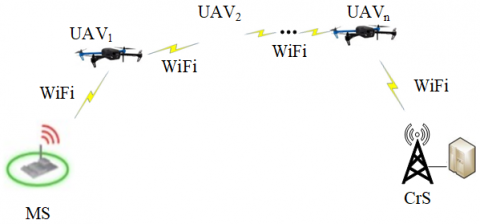
The Fukushima Nuclear Power Plant (NPP) accident showed that wired networks, connecting measuring stations (MS) of the automated radiation monitoring system to the crisis centre (CrS), are vulnerable to both natural and man-made disasters. To cope with the similar problems, a drone-based wireless subsystems (UAV-enabled wireless networks) can be deployed.
However, approaches for design of the subsystems have some restrictions and disadvantages. Currently, the design of monitoring systems based on UAVs takes place after a crisis occurs in a limited time, which does not always allow making an optimal system that meets all the requirements.
These monitoring systems design as a unique samples and it leads to high costs and difficulties with theirs scaling and changing. The use of the unified procedures for designing monitoring systems for critical infrastructure objects can provides:
An algorithm for justifying composition and utilization of monitoring systems for critical infrastructure objects based on the theory of transport systems considering possible types of the monitoring missions is proposed.
1.2 State of the art
Nowadays, the problems of using UAV-based monitoring systems are considered in many studies. UAV can perform different tasks during monitoring of the critical infrastructure objects. For example:
A scheduling problem in which UAVs must be recharged during a long-term mission described in study [9]. The work proposes a separate team of charging robots that the UAVs can dock with in order to recharge. The aim of the study is to schedule and plan cost-effective paths for charging ground robots during the UAVs mission.
Paper [10] presents a greedy strategy for coordination between the mobile refueling unmanned ground vehicle and the UAV for successful mission accomplishment. A Matlab simulation is used for testing and validation the strategy.
The autonomous battery exchange operation for small scale UAVs is presented in work [11]. There is used a mobile ground vehicle as a platform for robotic arm and service station with battery exchange mechanism. The aim of work is to describe the means to increase the autonomy of unmanned systems.
Work [12] presents a mechanism to control the charging schedule in multi-UAV setting in the presence of mobile charging stations. The main specialty in this paper is the lack of prior knowledge on the distribution of the number of drones participating in the auction.
Manini et al. [13] offer to utilize a ground-based refueling vehicle to increase the operational possibilities of a UAV. A two-stage strategy for coupled route planning for UAV and refueling vehicle is developed. The first stage includes computation a minimal number of sites for refueling. The second stage includes multiple Mixed-Integer Linear Programming formulations for planning optimal routes for the UAV and the refueling vehicle with set of refueling sites generated in stage one.
The problem of achieving continuous environment surveillance by using energy-constrained UAVs which are supported by mobile charging stations is researched by Seyedi et al. [14]. In the work the routes of all vehicles and the schedule of UAVs charging are planned for minimizing the time between two flights over to areas of interest.
Work [15] describes an approach for planning a route for energy‐limited UAV and routes for the unmanned ground vehicles with determining the locations of charging stations. The authors present different variants for charging: multiple stationary charging stations, single mobile charging station, and multiple mobile charging stations.
In paper [16] solve problems of route optimization for team of UAVs, which monitoring a set of objects in the presence of mobile starting/landing sites and resource limits.
Work [17] presents an overview of utilization UAVs in different engineering applications.
Paper [18] presents to design and fabricate a UAV-based air monitoring system to monitor air pollutant emissions over an oil field.
Tmušić et al. [19] describe the environmental conditions, constraints, and variables that could possibly be explored from UAV platforms and offer protocols that can be applied under all scenarios.
Thus, most of the considered works propose different approaches to planning routes for UAVs and refueling/charging vehicle during continuous monitoring missions. However, the mentioned works do not pay due attention to the problem of substantiating the quantitative composition of the monitoring system, both UAVs and charging stations, and the specifics of planning their use, taking into account various types of missions and their features.
1.3 Aim and structure
The aim of the work is to develop an algorithm of justifying composition and utilization of monitoring systems for critical infrastructure objects which make it possible to define the monitoring system composition taking into account the requirements that are put forward to the monitoring system, namely: the size of the monitoring area (the number of ground objects from which data is collected), the range, the frequency of transmission, the volume of transmitted data, the time of the system operation.
If we consider the data in the form of a cargo, and the UAV as a form of transport for this cargo, then the monitoring system can be considered as a system for collecting and transporting data. This approach allows applying the apparatus of the theory of transport systems for the analysis of monitoring systems.
UAVs form the transport subsystem of the monitoring system and can be considered as:
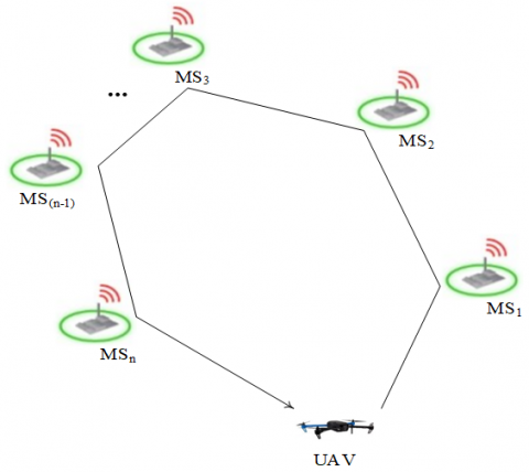
Figure 1. An example of simple monitoring system
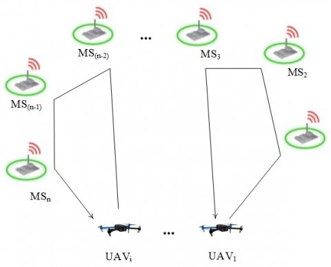
Figure 2. Monitoring system as fleet of the same type UAVs
Figure 3. Monitoring system as fleet of the same type UAVs as a chain
Figure 4. Monitoring system as homogeneous set of the same type UAV fleets
When using UAVs with electric traction as part of monitoring systems, it may be necessary to restore the charge of on-board power sources in the process of performing tasks. This task can be performed using ABRAS, which are considered as a subsystem for ensuring the functioning of the transport system.
Deploying charging/replacement stations on aerial platforms allows quickly traveling between target points of the route and avoiding problems related to damaged roads.
The following are the factors influencing the structure and composition of the monitoring system:
The composition of the monitoring system is also influenced by:
Structurally, the work consists of 5 sections: introduction with the motivation of ongoing research, analysis of the up to date results in the researched field; the second is devoted to the description of the and methods for justifying composition and utilization of monitoring systems; the third is to present a practical case of the algorithm application; the fourth one is dedicated to the description of the results obtained and the discussion; the last one is conclusions with indication of the directions of future research.
2.1 Algorithm for forming the structure and composition of the monitoring system
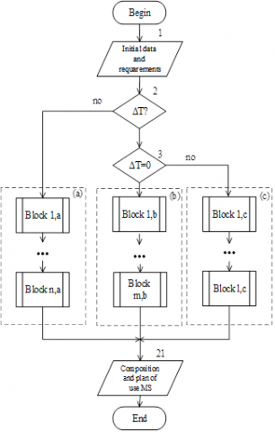
Figure 5. General algorithm for justifying monitoring system composition and use planning
Depending on the requirement for the interval of data receipt the algorithm considers three options for the composition of monitoring system (Figure 5):
a) No any restrictions - simple system with one UAV
b) Requirement of continuous long term data transfer - communication line from several UAVs;
c) Time frames for data obtaining is set - a system of several UAVs, providing collection and transmission of data in the required time.
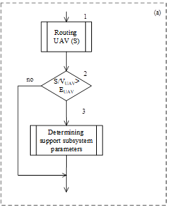
The procedures for each structure will be described further in more detail. The algorithm provides an optimization stage, the features of which will be described below. The algorithm branch (a) for MS (without any restrictions) is shown in Figure 6 and includes follow steps.
A route for the UAV is planned (Figure 6, block 1) and the route flight time is compared with the maximum flight endurance of the UAV (Figure 6, block 2).
If the route flight time is longer, the parameters of the support subsystem are determined (Figure 6, block 3).
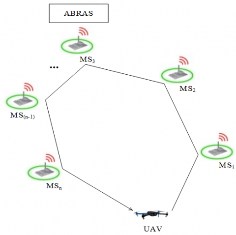
The required numbers of ABRAS and their location point are also determined (see Figure 7) [8].
Figure 6. Algorithm branch (a) for monitoring system without any restrictions
Figure 7. An example of the simple monitoring system with UAV and ABRAS
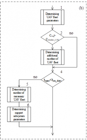
The algorithm branch for structure (b) (long-term data transfer is required) is shown in Figure 8 and includes follow steps.
The first step of the algorithm branch is to determine the number of UAVs required to form a data transmission line (Figure 8, block 1).
Figure 8. Algorithm branch (b) for monitoring system with requirement of long-term data transfer
The total number of the UAVs for the wireless segment (UAV fleet) is calculated as:
$n=\frac{{{D}_{\left( MS-CrS \right)}}}{2{{R}_{wireless\_UAV}}}$ (1)
where, D(MS-CrS) is the distance between the MS and CrS; Rwireless_UAV is the range of the onboard wireless equipment of the UAV.
At the second step, the condition of ensuring the required data transfer rate is checked (Figure 8, block 2).
If the condition is not met (Figure 8, block 3), the number of additional UAV fleets calculated as:
$m=\frac{{{C}_{req}}}{{{C}_{wireless\_UAV}}}-1$ (2)
where, Cwireless_UAV -data transfer rate of wireless equipment installed on the UAV; Creq-required data transfer rate from the ground MeS.
After that, the required time for continuous long-term transmission data is compared with the maximum flight endurance of the UAV (Figure 8, block 4).
The duration of the duty time for the UAV fleet can be determined by the following expression:
$\begin{align} & {{t}_{on\_duty}}={{E}_{UAV}}-\frac{2\max [{{S}_{\text{UAV}{{\text{1}}_{{}}}}}\text{; }\ldots ;\text{ }{{\text{S}}_{\text{UAVn}}}]}{{{v}_{UAV}}}- \\ & -{{t}_{wireless\_conf}}. \\\end{align}$ (3)
where, EUAV is the maximal flight endurance of the UAV; SUAV1 /.../ SUAVn is the flight distance for UAV1/ /UAVn between its location point in the wireless segment and the take on site; VUAV is the speed of the UAV; twireless_conf is the time to set up the wireless network configuration.
To ensure the persistent operation of the UAV-based monitoring system, it proposed to use the shift schedule for the UAV fleets. The necessary number of the UAV fleets (shifts) for ensuring the persistent operation of the monitoring system can be determined as (Figure 8, block 5):
$l=1+\frac{{{t}_{oper}}}{{{t}_{on\_duty}}\quad+{{t}_{repl\_bat}}}$ (4)
where, trepl_bat is the time to replace the battery at the ABRS.
Finally, the parameters of the support subsystem are determined for this case. There are determined the necessary numbers of ABRAS, their parameters and location point [20].
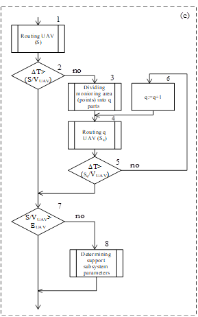
The branch of the algorithm for structure (c) (with time frames for data obtaining) is shown in Figure 9.
Figure 9. Algorithm branch (c) for monitoring system with time frames for data obtaining
First step (Figure 9, block 1) is similar with first step of the algorithm branch for structure (a) (Figure 7, block 1).
Next, the route flight time is compared with the time frames for data obtaining (Figure 9, block 2).
If the route flight time is longer, the target area is divided into parts (Figure 9, block 3, block 6) and routes for the each UAVs are planned (Figure 9, block 4), until the route flight time of UAV for each part is less than or equal to the required time frames for data obtaining (Figure 9, block 5).
After that, the route flight time of each UAVs is compared with the maximum flight time of the UAV (Figure 9, block 7).
If the route flight time is longer, the parameters of the support subsystem are determined (Figure 9, block 8).
2.2 Methods used for planning of monitoring systems utilization
It is clear that the time, which is required to visit all the objects on the route, should be minimized. It can be formulated as the Travelling Salesman Problem (TSP) in the absence of any additional restrictions [21].
However, the UAV may not have enough battery life to complete its mission without reconfiguring its depot to replace the battery when objects are scattered over a large area. The UAV can change the battery using the ABRAS directly on the route in such case. It leads to a new version of the TSP with two routes: UAV and ABRAS. It could be in another way, when it is distribution target area or objects between several UAVs and it can be formulated as the Multiple Travelling Salesman Problem (MTSP).
The following methods are used for that purpose [22, 23]:
Using of these methods allows planning and evaluating the capabilities of the designed monitoring systems.
Figure 10. Scheme of Scenario
The following scenario is considered in the paper. The wired networks that connecting the 11 measuring stations with CrS were damaged as a result of the accident at the Zaporizhzhya NPP. It is necessary to carry out monitoring, including the flight of 11 measuring stations to collect radiation control data from them (Figure 10).
Table 1. Abbreviations / symbols and its meaning
|
Abbreviation /symbol |
Abbreviation /symbol meaning |
|
CrS |
Crisis centre |
|
DH/DQ |
Depot for the ABRAS / for the quadcopter |
|
MS |
Measuring station |
|
NPP |
Nuclear power plant |
|
Location of the MS |
|
|
Location of the MS with the place for battery replacement |
|
|
Automatic battery replacement aerial system based on the SL-231 Scout unmanned helicopter |
|
|
Quadcopter |
|
|
Depot for the quadcopter |
|
|
Quadcopter route |
|
|
Automatic battery replacement aerial system route |
The Wi-Fi equipment hosted on the MS and the built-in WiFi equipment of the DJI Mavic 2 Enterprise Dual quadcopter allow you to accomplish this mission by the connection between the MS and the quadcopter hovering on the MS for the required time. For the quadcopter, the quadcopters depot is the starting and ending point of the route.
The MS is a route point for visiting the quadcopter. The support subsystem is presented as the SL-231 Scout helicopter, capable of operating in unmanned mode, which is used as a platform for an automatic battery replacement system.
Since the paper has numerous abbreviations and symbols, let’s present them in Table 1.
Assumptions and initial data:
Distances between route points presented in Table 2. Requirement is the following: it is necessary to obtain data from MSs one time an hour.
Table 2. Distances between route points, km
|
Point |
Points |
|||||||||||
|
DQ |
MS8 |
MS14 |
MS16 |
MS19 |
MS18 |
MS15 |
MS9 |
MS17 |
MS10 |
MS11 |
MS1 |
|
|
DQ |
0 |
6.92 |
3.16 |
2.75 |
2.02 |
1.86 |
2.31 |
5.39 |
1.12 |
1.27 |
4.57 |
1.16 |
|
MS8 |
6.92 |
0 |
5.85 |
4.89 |
5.64 |
5.34 |
4.75 |
3.68 |
6.16 |
6.03 |
5.35 |
8.07 |
|
MS14 |
3.16 |
5.85 |
0 |
1.49 |
1.25 |
3.77 |
3.27 |
6.17 |
2.05 |
3.48 |
6.24 |
4.04 |
|
MS16 |
2.75 |
4.89 |
1.49 |
0 |
0.79 |
0.71 |
1.88 |
6.16 |
4.48 |
2.41 |
4.82 |
3.7 |
|
MS19 |
2.02 |
5.64 |
1.25 |
0.79 |
0 |
0.56 |
2.21 |
5.24 |
0.91 |
2.3 |
5.16 |
3.12 |
|
MS18 |
1.86 |
5.34 |
3.77 |
0.71 |
0.56 |
0 |
1.59 |
4.71 |
0.85 |
1.79 |
4.54 |
3.03 |
|
MS15 |
2.31 |
4.75 |
3.27 |
1.88 |
2.21 |
1.59 |
0 |
3.25 |
1.96 |
1.27 |
2.99 |
3.39 |
|
MS9 |
2.31 |
3.68 |
6.17 |
6.16 |
5.24 |
4.71 |
3.25 |
0 |
5.23 |
4.15 |
1.83 |
6.26 |
|
MS17 |
1.12 |
6.16 |
2.05 |
4.48 |
0.91 |
0.85 |
1.96 |
5.23 |
0 |
1.56 |
4.76 |
2.27 |
|
MS10 |
1.27 |
6.03 |
3.48 |
2.41 |
2.3 |
1.79 |
1.27 |
4.15 |
1.56 |
0 |
3.39 |
2.16 |
|
MS11 |
4.57 |
5.35 |
6.24 |
4.82 |
5.16 |
4.54 |
2.99 |
1.83 |
4.76 |
3.39 |
0 |
5.17 |
|
MS1 |
1.16 |
8.07 |
4.04 |
3.7 |
3.12 |
3.03 |
3.39 |
6.26 |
2.27 |
2.16 |
5.17 |
0 |
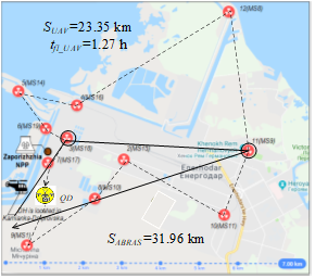
By solving the TSP through the Evolutionary solving method in Excel the shortest possible route for UAV that visits every MS exactly once and returns to the quadcopter’s depot (Figure 11) was found. It follows the route DQ-MS1-MS10-MS15-MS11-MS9 (located point for battery replacement #1)-MS8-MS16-MS14-MS19-MS18 (located point for battery replacement #2)-MS17-DQ. Total route flight time is 1.27 h.
In case of considering the route through the prism of requirements then it is necessary to divide the route into parts because the route flight time is more than one hour.
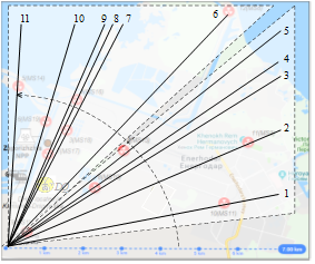
At the first stage, the number of measuring stations divided into two parts. The approach to dividing the target area is shown on (Figure 12).
The angles of vectors from the origin of the coordinate system to the points of location of each object are used to number the objects in ascending order of the angle value. The origin of the coordinate system is positioned to cover all objects. After that, the number of items is divided into parts.
Figure 11. The shortest possible route for UAV (that visits every MS just one time) and ABRAS route
The number of objects in each area should not differ by more than one.
Two sets of MSs are obtain by dividing:
The routes for UAVs that visits every MS of each sets and for ABRAS are shown in the Figure 12.
Figure 12. Approach to dividing the target area
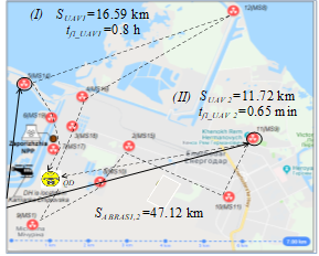
The shortest possible route for UAV that visits every MS of first set is follow: DQ-MS18-MS16-MS8 (there is located point for battery replacement)-MS14-MS19-MS17-DQ. Total route flight time is 0.82 h.
The shortest possible route for UAV that visits every MS of second set is follow: DQ-MS1-MS10-MS15-MS11-MS9 (there is located point for battery replacement)-DQ. Total route flight time is 0.65 h (Figure 13).
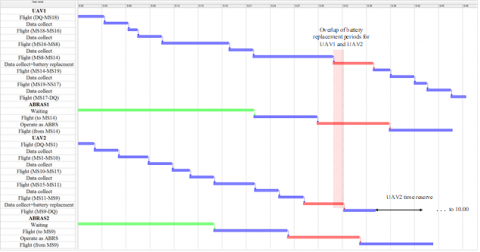
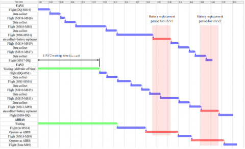
The Gantt chart of tasks for UAVs that visits every MS of each sets and for ABRASs is shown in Figure 14.
Thus, time to obtain data from MSs after divided target area is less than one hour and satisfies the requirement but it is necessary two ABRAS for battery replacement in this case. Total route of ABRAS1 and ABRAS2 is 47.12 km.
Figure 13. The shortest possible routes for UAVs that visits every MS of each sets and ABRAS routes
Considering the Gantt chart in Figure 14, we conclude that the periods required replacing UAVs batteries are overlapped. This necessitates two ABRASes. However, at the same time, the second UAV has a time reserve: $\left( \Delta T-{{t}_{oper}} \right)=1-0.65=0.35$h. If UAV2 will take-off by 0.28 h later, the time for replacing batteries and a flight time between replacement points will be enough for only one ABRAS. The time of UAV2 landing will be early then one hour.
${{t}_{w\_UAV2}}+{{t}_{fl\_UAV2}}=0.28+0.65=0.93\text{h}$ (5)
where, ${{t}_{w\_UAV2}}$ is the UAV2 waiting time before taking off; ${{t}_{fl\_UAV2}}$ is the UAV2 route flight time. The Gantt chart of tasks for UAVs and ABRAS with shift UAV2 take off time is shown in Figure 15.
Figure 14. The Gantt chart of tasks for UAVs that visits every MS of each sets and for ABRASes
Figure 15. The Gantt chart of tasks for UAVs and ABRAS with shift UAV2 take off time
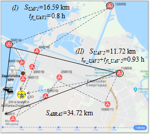
The ABRAS route will be only 34.72 km in this case instead 57.1 km in previous one (Figure 16).
Thus, the optimization stage allows obtaining a balanced solution from the standpoint of resource consumption of both components of the monitoring system and the UAV as a transport subsystem and ABRAS as a support subsystem.
Figure 16. Optimal result of UAVs and ABRAS utilization
The algorithm of justifying composition and utilization of monitoring systems for critical infrastructure objects allows:
The optimization stage allows finding a more profitable compromise solution, taking into account the consumption of resources of all components of the monitoring system.
Application of the developed approach and algorithms decreases time of monitoring on 25% and allows to use only one ABRAS.
In future research, it is planned to develop an approach for design of an automated control for UAV fleet of monitoring system considering failures of drones [24] and application of space-structure redundancy of the fleet and control stations [25].
|
${{C}_{req}}$ |
required baud rate, b. s-1 |
|
${{C}_{wireless\_UAV}}$ |
UAV baud rate, b. s-1 |
|
${{D}_{\left( MS-CrS \right)}}$ |
required data transmission range, m |
|
${{E}_{UAV}}$ |
UAV maximum flight duration, min |
|
$k$ |
number of target points for monitoring |
|
$l$ |
necessary number of the UAV fleets (shifts) for ensuring the persistent operation of the monitoring system |
|
$m$ |
number of additional UAV fleets |
|
$n$ |
total number of the UAVs for the wireless segment (UAV fleet) |
|
${{R}_{wireless\_UAV}}$ |
range of wireless data transmission UAV onboard equipment, m |
|
${{S}_{\text{UAVn}}}$ |
UAV flight distance between its location point in the wireless segment and the take on site, km |
|
${{t}_{bat\_repl}}$ |
battery replacement time, h |
|
${{t}_{fl\_UAV2}}$ |
UAV2 route flight time, h |
|
${{t}_{on\_duty}}$ |
duty time for the UAV fleet, h |
|
${{t}_{oper}}$ |
duration of the monitoring system operating, h |
|
${{t}_{w\_UAV2}}$ |
UAV waiting time before taking off, h |
|
${{t}_{wireless\_conf}}$ |
time to set up the wireless network configuration, h |
|
${{V}_{ABRAS}}$ |
ABRAS speed, km. h-1 |
|
${{V}_{UAV}}$ |
UAV speed, km. min-1 |
|
$({{x}_{k}};{{y}_{k}})$ |
target points coordinates of a rectangular system of coordinates |
|
$\Delta T$ |
interval of data collection and transmission, h |
[1] Connora, D., Martin, P.G., Scott, T.B. (2016). Airborne radiation mapping: Overview and application of current and future aerial systems. International Journal of Remote Sensing, 37(24): 5953-5987. https://doi.org/10.1080/01431161.2016.1252474
[2] Burtniak, V., Zabulonov, Y., Stokolos, M., Bulavin, L., Krasnoholovets, V. (2018). Application of a territorial remote radiation monitoring system at the Chornobyl nuclear accident site. Journal of Applied Remote Sensing, 12(4): 046007. https://doi.org/10.1117/1.JRS.12.046007
[3] Čerba, Š., Lüley, J., Vrban, B., Osuský, F., Nečas, V. (2020). Unmanned radiation-monitoring system. IEEE Transactions on Nuclear Science, 67(4): 636-643. https://doi.org/10.1109/TNS.2020.2970782
[4] Aleotti, J., Miccon, G., Caselli, S., Benassi, G., Zambelli, N. (2017). Detection of nuclear sources by UAV teleoperation using a visuo-haptic augmented reality interface. Sensors, 17(10): 2234 https://doi.org/10.3390/s17102234
[5] Xiao, P., Tang, B., Huang, X., Wang, P., Sheng, L., Xiao, W., Zhu, X., Zhou, C. (2019). Locating lost radioactive sources using a UAV radiation monitoring system. Applied Radiation and Isotopes, 150: 1-13. https://doi.org/10.1016/j.apradiso.2019.04.037
[6] Martin, P.G., Payton, O.D., Fardoulis, J.S., Richards, D.A, Yamashiki, Y., Scott, T.B. (2016). Low altitude unmanned aerial vehicle for characterising remediation effectiveness following the FDNPP accident. Journal of Environmental Radioactivity, 151(1): 58-63. https://doi.org/10.1016/j.jenvrad.2015.09.007
[7] Fesenko, H., Kharchenko, V., Sachenko, A., Hiromoto, R., Kochan, V., Kor, A., Rucinski, A. (2018). An Internet of Drone-based multi-version post-severe accident monitoring system: structures and reliability. Dependable IoT for Human and Industry Modeling, Architecting, Implementation, 197-217
[8] Fesenko, H., Kliushnikov, I., Kharchenko, V., Rudakov, S., Odarushchenko, E. (2020). Routing an Unmanned Aerial Vehicle During NPP Monitoring in the Presence of an Automatic Battery Replacement Aerial System. In 2020 11th IEEE international conference on Dependable Systems, Services and Technologies (DESSERT), 34-39. https://doi.org/10.1109/DESSERT50317.2020.9125080
[9] Mathew, N., Smith, S.L., Waslander, S.L. (2015). Multirobot rendezvous planning for recharging in persistent tasks. IEEE Transactions on Robotics, 31(1): 128-142. https://doi.org/10.1109/TRO.2014.2380593
[10] Maini, P., Sujit, P.B. (2015). On cooperation between a fuel constrained UAV and a refueling UGV for large scale mapping applications. In International Conference on Unmanned Aircraft Systems (ICUAS), pp. 1370-1377. https://doi.org/10.1109/ICUAS.2015.7152432
[11] Barrett, E., Reiling, M., Mirhassani, S., Meijering, R., Jager, J., Mimmo, N., Callegati, F., Marconi, L., Carloni, R., Stramigioli, S. (2018). Autonomous battery exchange of UAVs with a mobile ground base. In 2018 IEEE International Conference on Robotics and Automation (ICRA), pp. 699-705. https://doi.org/10.1109/ICRA.2018.8460201
[12] Shin, M., Kim, J., Levorato M. (2019). Auction-based charging scheduling with deep learning framework for multi-drone networks. in IEEE Transactions on Vehicular Technology., 68(5): 4235-4248. https://doi.org/10.1109/TVT.2019.2903144
[13] Maini, P., Sundar, K., Singh, M., Rathinam, S., Sujit, P. B. (2019). Cooperative aerial-ground vehicle route planning with fuel constraints for coverage applications. In IEEE Transactions on Aerospace and Electronic Systems, 55(6): 3016-3028. https://doi.org/10.1109/TAES.2019.2917578
[14] Seyedi, S., Yazicioğlu, Y., Aksaray, D. (2019). Persistent surveillance with energy-constrained UAVs and mobile charging stations. IFAC-PapersOnLine, 52(20): 193-198. https://doi.org/10.1016/j.ifacol.2019.12.157
[15] Yu, K., Budhiraja, A. K., Buebel, S., Tokekar, P. (2019). Algorithms and experiments on routing of unmanned aerial vehicles with mobile recharging stations. Journal of Field Robotic, 36: 602-616. https://doi.org/10.1002/rob.21856
[16] Horbulin, V.P., Hulianytskyi, L.F., Sergienko, I.V. (2020). Optimization of UAV Team Routes in the Presence of Alternative and Dynamic Depots. Cybernetics and Systems Analysis, 56: 195-203. https://doi.org/10.1007/s10559-020-00235-8
[17] Giordan, D., Adams, M.S., Aicardi, I., Alicandro, M., Allasia, P., Baldo, M., Troilo, F. (2020). The use of unmanned aerial vehicles (UAVs) for engineering geology applications. Bulletin of Engineering Geology and the Environment, 79(7): 3437-3481. https://doi.org/10.1007/s10064-020-01766-2
[18] Liu, S., Yang, X., Zhou, X. (2021). Development of a low-cost UAV-based system for CH4 monitoring over oil fields. Environmental Technology, 42(20): 3154-3163. https://doi.org/10.1080/09593330.2020.1724199
[19] Tmušić, G., Manfreda, S., Aasen, H., James, M.R., Gonçalves, G., Ben-Dor, E., Brook, A., Polinova, M., Arranz, J.J., Mészáros, J., Zhuang, R., Johansen, K., Malbeteau, Y., de Lima, I.P., Davids, C., Herban, S., McCabe, M.F. (2020). Current Practices in UAS-based Environmental Monitoring. Remote Sensing, 12(6): 1001. https://doi.org/10.3390/rs12061001
[20] Kliushnikov, I., Fesenko, H., Kharchenko, V. (2019). Using automated battery replacement stations for the persistent operation of UAV-enabled wireless networks during NPP post-accident monitoring. Radioelectronic and Computer Systems, 4: 30-38. https://doi.org/10.32620/reks.2019.4.03
[21] Htun, T.T. (2018). A Survey Review on Solving Algorithms for Travelling Salesman Problem. International Journal of Scientific and Research Publications, 8(12): 630-633. https://doi.org/10.29322/IJSRP.8.12.2018.p8481
[22] Rothlauf, F. (2016). Representations for evolutionary algorithms. In 2016 on Genetic and Evolutionary Computation Conference Companion (GECCO'16 Companion), pp. 413-434. https://doi.org/10.1145/2908961.2926981
[23] Zhang, J., Ding, G., Zou, Y., Qin, S., Fu, J. (2019). Review of job shop scheduling research and its new perspectives under Industry 4.0. Journal of Intelligent Manufacturing, 30: 1809-1830. https://doi.org/10.1007/s10845-017-1350-2
[24] Fesenko, H., Kharchenko, V., Zaitseva, E. (2019). Evaluating reliability of a multi-fleet with a reserve drone fleet: an approach and basic model. In 2019 IEEE International Conference Information and Digital Technologies (IDT’2021), pp. 128-132. https://doi.org/10.1109/DT.2019.8813738
[25] Fesenko, H., Kharchenko, V. (2019). Reliability models for a multi-fleet of drones with two-level hot standby redundancy considering a control system structure. In 2019 10th IEEE International Conference on Intelligent Data Acquisition and Advanced Computing Systems: Technologies and Application (IDAACS), pp. 1030-1035. https://doi.org/10.1109/IDAACS.2019.8924404