Lu Zhang | Haoyu Li | Hongbin Shen | Bin Sun | Xiguang Chen | Ziwei Dong*
© 2026 The authors. This article is published by IIETA and is licensed under the CC BY 4.0 license (http://creativecommons.org/licenses/by/4.0/).
OPEN ACCESS
To the end of coping with the problem of less features and low diagnosis accuracy in diagnosing wrong synchronous motor at complex situation we have brought up a sort of system depending upon many-sensors information mixture along with the multiple - scales spare convolution neural network as well as the convolutional block attention module (CBAM). Multi-sensor signals such as stator phase voltage, stator phase current and rotor current etc., are then converted into RGB image to improve the feature expression ability and lower the effect caused by noise. Multiscale Residual Convolutional Network and Residual Learning, which is used to extract fault features at various resolutions, makes training more stable and reduces the degradation of gradients. And CBAM will be introduced to select important channels and spatial information, to help make our model more distinguishable. In experiments for 300W three-phase synchronous motor, the proposed method has a diagnostic precision of 95.63% on electrical faults. We also do some checks on the method using other data sets, like CWRU and Southeast Universities’, when using different amounts of training examples it still gives really good results like when they are 99.56% accurate or even up towards that top of around 98.65%. When there’s lots of stuff to check about working differently than normal too though they all stay pretty high too, way above anything less than those 99.6%. The proposed framework greatly enhances its accuracy and robustness, which offers a good and feasible scheme for the smart fault analysis of synchronous motors.
synchronous motor, fault diagnosis, multi-sensor data fusion, multiscale residual network
Synchronous motors are playing an essential role inside current industrial system like Manufacturing Equipment or Power Generation System from the Wind, Transportation, Ships’ Propulsion etc. In the wake of fast pace growth in industrial automation, Internet of Things (IOT), smart manufacturing, it is required that we make sure these kinds of systems run safely and dependently. However synchronous motor has been suffering lots of damage because it runs too much under bad working environment, so it is likely that some trouble happens at its body part or electrical part and that would not just break something but could also be very dangerous, maybe losing money. So making good fault checking ideas about those synchronous motors became really important now [1].
The conventional fault diagnosis ways can basically fall under models based approach, signal processing method and artificial intelligence way. The Model-based method depend on precise math description of motor system that is hard because its non-liner and complicated environment. Using signal processing like Fourier transform wavelet transform, can extract fault features from measured signals, but their effectiveness is limited in non-stationary or noisy environments [2]. In recent years, artificial intelligence, particularly deep learning, has demonstrated superior capability in feature extraction and pattern recognition, enabling more accurate and automated fault diagnosis without relying heavily on prior knowledge [3].
Though it’s true there has been progress, those current DL—based ones still cannot be used easily universally applicable. First, a lot of stuff depends on one kind of information, it isn’t able to completely take in all the complicated things happening with electricity and moving parts at the same time, and they also really easily get mixed up if there’s any bumps in what it hears [4]. Second, conventional convolutional neural networks often employ single-scale feature extraction, leading to insufficient representation of fault characteristics across different frequency bands. Third, most models lack effective mechanisms to distinguish the importance of features in different channels and spatial locations, which restricts their diagnostic performance and robustness [5].
Regarding the challenges in this paper, there will be presented a framework of DL based on a FDS for the synchronous electric-mechanical drive system. First off we come up with a way to do multisensors stuff for integrating all our stator voltages, all those stator currents as well as all our nice old rotors currents that we take to get into some nicer RGB form, which helps make things stand out more [6]. Second, a multiscale residual convolutional network combined with a convolutional attention mechanism is constructed to extract rich fault features and improve model training stability. The residual structure mitigates gradient vanishing, while the attention mechanism adaptively emphasizes informative features. Finally, extensive experiments are conducted on both electrical and mechanical fault datasets, including real-world engineering data, to test whether the proposed method is really good, as described in this paragraph, to show that the result we found was actually accurate. It is obvious from the results that our method has the most favorable performance when considering diagnostic capability, noisy data tolerance, and overall engineering usefulness compared to other previous attempts.
Motor fault diagnosis technology has undergone significant development with the advancement of power electronics, sensing technologies, and intelligent algorithms. Since the late 20th century, researchers from the United States, Europe, and Japan have conducted extensive studies on motor fault diagnosis and established dedicated research centers, promoting its application in aerospace, transportation, and industrial systems. With the rapid progress of computer technology and high-precision sensors, fault diagnosis methods have evolved from traditional analytical approaches to data-driven intelligent methods [7]. In China, research on motor fault diagnosis began relatively later but has developed rapidly alongside the advancement of industrial automation and intelligent manufacturing technologies [8].
At present, motor fault diagnosis is widely applied in various industrial scenarios, including manufacturing systems, wind turbines, electric transportation, and marine propulsion. Due to long-term operation under complex and harsh environments, motors are susceptible to multiple types of faults, such as electrical faults, mechanical faults, and excitation faults [9]. Electrical faults commonly include winding short circuits and grounding faults, while mechanical faults are mainly associated with bearing defects and rotor eccentricity [10]. Among these, bearing faults are the most frequent and critical, significantly affecting system reliability and operational stability. As a result, accurate and real-time fault diagnosis has become essential for ensuring the safety and efficiency of electro-mechanical systems [11].
With the increasing demand for intelligent monitoring, modern fault diagnosis systems are gradually shifting toward automation, data fusion, and intelligent decision-making [12]. The integration of multi-sensor data and advanced algorithms enables more comprehensive representation of motor operating conditions, providing new opportunities for improving diagnostic accuracy and robustness.
3.1 Overview
This brief section gives some theoretical basis for what is proposed here on the subject of faults to detect. We can use convolutional neural network. signal-to-image mapping, residual learning, multiscale convolution, and multi-sensor data fusion [13].
3.2 Fundamentals of convolutional neural networks
Convolutional neural networks are feedforward networks that use local connectivity and have weight sharing. The main layers are the Convolutional Layers, Pooling Layer and Fully Connected Layer [14].
3.2.1 Convolutional layer
As shown in Figure 1 and Figure 2, the convolutional layer extracts features from the input through learnable kernels. For a neuron receiving D inputs, the weighted sum is expressed as:
$\text{z=}\underset{\text{d=1}}{\overset{\text{D}}{\mathop \sum }}\,{{\text{ }\!\!\omega\!\!\text{ }}_{\text{d}}}{{\text{x}}_{\text{d}}}\text{+b=}{{\text{ }\!\!\omega\!\!\text{ }}^{\text{T}}}\text{x+b}$ (1)
and the activation value is:
$\text{a=f(z)}$ (2)
The mathematical form of the convolutional layer is given by:
${{\text{z}}^{\text{l}}}\text{=}{{\text{ }\!\!\omega\!\!\text{ }}^{\text{l}}}\text{*}{{\text{a}}^{\text{l-1}}}\text{+}{{\text{b}}^{\text{l}}}$ (3)
And
$\text{Y=W*X}$ (4)
Figure 1. The convolution layer
Figure 2. Convolutional layer
3.2.2 Feature downsampling and output mapping
Pooling is reducing dimensions and retaining some informative features. Max Pooling, Average Pooling is given as follows [15].
$\text{y}_{\text{m,n}}^{\text{d}}\text{=}\underset{\text{i}\in \text{R}_{\text{m,n}}^{\text{d}}}{\mathop{\text{max}}}\,{{\text{x}}_{\text{i}}}$ (5)
$\text{y}_{\text{m,n}}^{\text{d}}\text{=}\frac{\text{1}}{\text{ }\!\!|\!\!\text{ R}_{\text{m,n}}^{\text{d}}\text{ }\!\!|\!\!\text{ }}\underset{\text{i}\in \text{R}_{\text{m,n}}^{\text{d}}}{\mathop \sum }\,{{\text{x}}_{\text{i}}}$ (6)
Use the softmax function as the output layer for classification:
${{\text{z}}_{\text{k}}}\text{=softmax(}{{\text{x}}_{\text{k}}}\text{)=}\frac{\text{exp(}{{\text{x}}_{\text{k}}}\text{)}}{\mathop{\sum }_{\text{i=1}}^{\text{K}}\text{exp(}{{\text{x}}_{\text{i}}}\text{)}}$ (7)
To avoid overfitting, dropout is introduced during training [16], as shown in Figure 3.
Figure 3. Example of the dropout method
3.3 Signal-to-image transformation
To improve the representation ability of one-dimensional vibration data, the original signal is converted into a two-dimensional grayscale image [17]. After segmenting the signal and arranging the sampled values into image pixels, the grayscale intensity is obtained by normalization:
$\text{P(j,k)=}\frac{\text{L((j-1) }\!\!\times\!\!\text{ N+k)-min(L)}}{\text{max(L)-min(L)}}\text{ }\!\!\times\!\!\text{ 255}$ (8)
This transformation enables the original signal characteristics to be represented by pixel intensity values, as shown in Figure 4.
Figure 4. Conversion of a 1D signal to a 2D grayscale image
3.4 Residual learning and multiscale convolution
Residual learning introduces shortcut connections between convolutional layers to improve gradient propagation and network training stability. In addition, multiscale convolution uses parallel convolution kernels with different sizes to extract fault features at different scales. The fused multiscale feature can be expressed as [18].
$\text{y=}{{\text{o}}_{\text{1}}}\text{+}{{\text{o}}_{\text{2}}}\text{+}\cdots \text{+}{{\text{o}}_{\text{n}}}$ (9)
Compared with single-scale convolution, this structure (Figure 5) can capture richer feature information [19].
Figure 5. Multi-scale convolution structure
4.1 Introduction
Synchronous motors are vulnerable to electrical faults under complex operating conditions, variable loads, and insulation aging. These faults may cause significant changes in stator voltage, stator current, and rotor current, thereby affecting system stability and operational safety. To address this issue, and there’s a new method of fault diagnosis, that involves several sensor combinations as well as a multi-scale residual convolutional network with convolutional block attention module (CBAM). It uses the synchronous motor electric fault data to evaluate and use the public machine fault dataset to validate the proposed approach.
4.2 Proposed method
4.2.1 Multi-sensor signal-to-RGB conversion
To improve the representation capability of multi-source signals, a fusion strategy is adopted in which three sensor signals are converted into a three-channel RGB image. Compared with conventional time-frequency image conversion methods, this strategy reduces preprocessing complexity and avoids excessive dependence on prior knowledge. The conversion process is shown in Figure 6.
Figure 6. Conversion of multi-sensor signals to RGB images
The collected multi-sensor data are represented as [20].
${{\text{X}}_{\text{sig}}}\text{= }\!\!\{\!\!\text{ }{{\text{x}}_{\text{ij}}}\text{:}{{\text{x}}_{\text{ij}}}\in {{\text{R}}^{\text{a }\!\!\times\!\!\text{ b}}}\text{ }\!\!\}\!\!\text{ }$ (10)
where, “a” denotes the number of sensors and “b” denotes the number of sampling points. Each channel is normalized into a pixel matrix:
$\text{PM }\!\!'\!\!\text{ (u,v)=}\frac{\text{L }\!\!'\!\!\text{ ((u-1) }\!\!\times\!\!\text{ k+v)-min(L }\!\!'\!\!\text{ )}}{\text{max(L }\!\!'\!\!\text{ )-min(L }\!\!'\!\!\text{ )}}\text{ }\!\!\times\!\!\text{ 255}$ (11)
The RGB image is then constructed by combining the three pixel matrices:
$\text{RGBM(u,v,}{{\text{C}}_{\text{rgb}}}\text{)=(PM }\!\!'\!\!\text{ (u,v),}{{\text{C}}_{\text{rgb}}}\text{)}$ (12)
4.2.2 Multiscale residual convolution module
A MSRC module for extracting the fault information out of an RGB image has been created. Module employs parallel convolutional kernel having size 3 × 3 and 5 × 5 and 7 × 7 to pick multi-scale data. Residual Blocks are then used to boost up feature propagation as well as to reduce gradient disappearance. MSRC structure and residual block can be seen in Figure 7 and Figure 8.
Figure 7. Multiscale residual convolution module
Figure 8. Residual blocks
4.2.3 Convolutional attention module
To further enhance feature discrimination, CBAM is incorporated after MSRC. The module includes channel attention and spatial attention, enabling the network to adaptively emphasize informative channels and spatial regions. The structure is shown in Figure 9.
Figure 9. Attention structure of convolutional block attention module (CBAM)
4.2.4 Overall framework
The complete framework is shown in Figure 10. Multi-sensor signals are first converted into RGB images, then processed by the MSRC and CBAM modules. Global average pooling is used to reduce feature dimensionality, and Softmax performs the final classification.
Figure 10. Deep learning framework
4.3 Experimental setup
Experiment was run with a synchronous motor fault system by means of stator phase voltages, stator phase current, and rotor current as the three inputs sensors. Open-Phase fault between Inverter-Synchronous Motor; two-Phase Short circuit; Single-Phase-to-Neutral Short Circuit; Rotor Excitation Voltage Open Circuit, Rotor Excitation Current Variation. The fault circuits are in Figures 11-15 and the motor and inverter parameters can be found in Table 1.
Figure 11. Circuit diagram of an open-phase fault between an inverter and a synchronous motor
Figure 12. Circuit diagram of two-phase short-circuit fault
Figure 13. Circuit diagram of single-phase and neutral short-circuit faults
Figure 14. Circuit diagram of rotor excitation voltage open circuit fault
Figure 15. Rotor excitation current change fault circuit diagram
Table 1. Technical parameters of the motor–inverter test platform
|
Parameter Description |
Numerical Value |
Unit |
|
Output power of synchronous motor |
300 |
W |
|
Rated rotor speed |
1345 |
rpm |
|
Fundamental frequency |
50 |
Hz |
|
Line voltage (Δ/Y connection) |
230/400 |
V |
|
Nominal stator current |
0.75 |
A |
|
Inverter power rating |
746 |
W |
|
Allowable inverter voltage range |
110–220 |
V |
|
Maximum output current of inverter |
8 |
A |
Table 2. Meaning of categorical labels
|
Label |
Fault Type |
Number of RGB Images |
|
0 |
Rotor excitation current variation |
500 |
|
1 |
Rotor excitation voltage open circuit |
500 |
|
2 |
Open-phase fault between inverter and synchronous motor |
500 |
|
3 |
Two-phase short circuit |
500 |
|
4 |
Single-phase-to-neutral short circuit |
500 |
For electrical fault diagnosis, we created 500 RGB images for every fault category, which were then separated into a training set containing 80%, a validation set containing 10%, and a testing set also containing 10%. Fault Labels and Samples Image are provided in Table 2 and Table 3. To verify generalization performance, the proposed method was also tested on the CWRU dataset and the Southeast University dataset.
Table 3. Fault classification accuracy of a single data
|
Input Data |
Convolutional Neural Network (CNN) (%) |
Long Short-Term Memory (LSTM) (%) |
Feedforward Neural Network (FNN) (%) |
Proposed Method (%) |
|
Stator current |
58.41 |
13.8 |
45.27 |
82.53 |
|
Stator voltage |
74.78 |
2.36 |
63.21 |
86.15 |
|
Rotor current |
75.81 |
1.94 |
67.85 |
87.31 |
4.4 Results and discussion
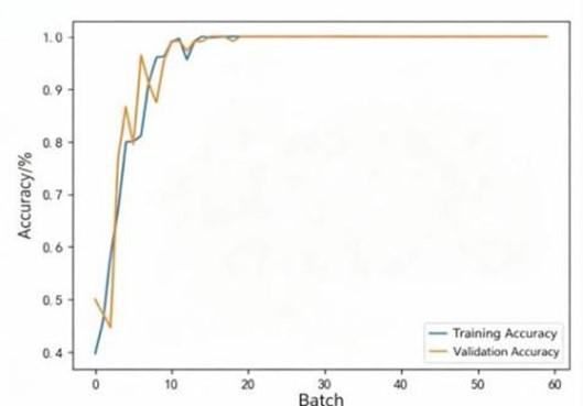
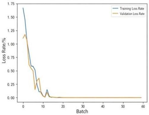
For synchronous motor electrical faults, the proposed method outperformed Convolutional Neural Network (CNN), Long Short-Term Memory (LSTM), and Feedforward Neural Network (FNN) under single-sensor, dual-sensor, and three-sensor settings. When all three signals were used jointly, the proposed method achieved a test accuracy of 95.63%, which was higher than CNN (91.12%), LSTM (72.43%), and FNN (66.71%). The training curves and confusion matrix are shown in Figure 16 and Figure 17.
Fault classification accuracy of various diagnostic methods are provided in Table 4. On the CWRU dataset, the proposed method achieved 99.56% accuracy at a 60% training rate and 98.65% at a 30% training rate, outperforming several representative deep learning models. Under different noise levels, the method also showed stronger robustness than the comparison methods, as illustrated in Figures 18–22.
(a) Training accuracy
(b) Training loss
Figure 16. Training performance of the proposed model
Figure 17. Confusion matrix
Figure 18. Training rate 60% confusion matrix
Figure 19. Training rate 30% confusion matrix
Figure 20. Classification performance of different models under various noise conditions
From Table 5, we can see that on the Southeast University dataset, the proposed method achieved 99.6% accuracy for both bearing and gearbox fault diagnosis under different operating conditions, indicating strong adaptability to multi-condition mechanical fault diagnosis tasks.
Table 4. Fault classification accuracy of various diagnostic methods
|
Method |
Test Accuracy (60% Training) (%) |
Test Accuracy (30% Training) (%) |
|
Proposed method |
99.56 |
98.65 |
|
LeNet |
79.57 |
21.62 |
|
VGG16 |
97.44 |
67.57 |
|
AlexNet |
97.33 |
25.23 |
|
MSCNN |
94.19 |
90.85 |
|
ResNet34 |
95.77 |
92.34 |
|
ResNet50 |
98.22 |
81.53 |
|
DRSN |
98.17 |
91.89 |
|
CNNLSTM |
96.15 |
89.16 |
Table 5. Accuracy under different operating conditions
|
Method |
G1 Bearing (%) |
G1 Gearbox (%) |
G2 Bearing (%) |
G2 Gearbox (%) |
|
LeNet |
79.0 |
65.4 |
73.4 |
63.0 |
|
VGG16 |
98.6 |
92.6 |
98.4 |
98.2 |
|
AlexNet |
99.0 |
94.6 |
98.6 |
92.2 |
|
ResNet34 |
99.0 |
98.2 |
99.0 |
99.0 |
|
ResNet50 |
98.6 |
98.2 |
99.0 |
95.4 |
|
TICNN |
99.2 |
99.0 |
97.4 |
98.6 |
|
Proposed Method |
99.4 |
99.8 |
99.6 |
99.4 |
Figure 21. Confusion matrix for rolling bearings under G1 conditions
Figure 22. Gearbox confusion matrix under G1 conditions
4.5 Summary
A fault diagnosis framework combining multi-sensor data fusion, MSRC, and CBAM was proposed in this section. By transforming multi-sensor signals into RGB images and integrating multiscale convolution with attention learning, the method effectively improves fault feature extraction and classification performance. Experimental results on synchronous motor electrical faults, CWRU, and Southeast University datasets demonstrate its effectiveness, robustness, and generalization capability.
We created a fault diagnosing system of synchronous motors using multi-sensor fusions combined with an multi-scale residual convolutional network as well as convolutional block attention module. By transforming the multi-sensor signal into an RGB representation it is able to obtain information about different parts of the signal that were not seen when looking at them using just one sensor on its own. This provides better representation of the features than traditional single sensor methods.
With multiscale convolution and residual learning it can get features with different scales but keep it trained normally. And the attention mechanism would adaptively focus on some more important channels and spatial features that might make up its more discrimination power overall.
From the result we found it was pretty accurate to find most of those electrical faults with this new method applied on synchronous motors. Evaluating CWRU and Southeast University datasets too, proving it’s really good at generalizing all the time even if there aren’t as much of them. It shows that the framework can offer an effective and reliable solution for intelligent diagnosis of faults in electro-mechanical systems.
This work was supported by the National Nature Science Foundation of China (Grant No.: 52305048; 52477035), the Zhiyuan Science Foundation of BIPT (Grant No.: 2025208; 2024101), and Shandong Key Laboratory of Advanced Motors and Electromechanical Systems (Grant No.: HLZDSY2025013).
[1] Wu, G., Yu, Y., Tu, W. (2021). A review of fault diagnosis of permanent magnet synchronous motors. Journal of Engineering Design, 28(5): 548-558.
[2] Tao, F., Qi, Q., Wang, L., Nee, A.Y.C. (2019). Digital twins and cyber–physical systems toward smart manufacturing and industry 4.0: Correlation and comparison. Engineering, 5(4): 653-661. https://doi.org/10.1016/j.eng.2019.01.014
[3] Consoli, A., Scarcella, G., Testa, A. (2001). Industry application of zero-speed sensorless control techniques for PM synchronous motors. IEEE Transactions on industry Applications, 37(2): 513-521. https://doi.org/10.1109/28.913716
[4] Liserre, M., Cardenas, R., Molinas, M., Rodriguez, J. (2011). Overview of multi-MW wind turbines and wind parks. IEEE Transactions on Industrial Electronics, 58(4): 1081-1095. https://doi.org/10.1109/TIE.2010.2103910
[5] Zheng, J.M., Wang, Z.H., Wang, D.X., Li, Y.Y., Li, M. (2017). Review of fault diagnosis of PMSM drive system in electric vehicles. In 2017 36th Chinese Control Conference (CCC), Dalian, China, pp. 7426-7432. https://doi.org/10.23919/ChiCC.2017.8028529
[6] Xu, X., Qiao, X., Zhang, N., Feng, J., Wang, X. (2020). Review of intelligent fault diagnosis for permanent magnet synchronous motors in electric vehicles. Advances in Mechanical Engineering, 12(7): 1687814020944323.
[7] Yang, Y., He, Q., Fu, C.Y., Liao, S.P., Tan, P. (2020). Efficiency improvement of permanent magnet synchronous motor for electric vehicles. Energy, 213: 118859. https://doi.org/10.1016/j.energy.2020.118859
[8] Torrent, M., Perat, J.I., Jiménez, J.A. (2018). Permanent magnet synchronous motor with different rotor structures for traction motor in high speed trains. Energies, 11(6): 1549. https://doi.org/10.3390/en11061549
[9] Eker, M., Gündogan, B. (2023). Demagnetization fault detection of permanent magnet synchronous motor with convolutional neural network. Electrical Engineering, 105(3): 1695-1708. https://doi.org/10.1007/s00202-023-01768-9
[10] Skowron, M., Krzysztofiak, M., Orlowska-Kowalska, T. (2022). Effectiveness of neural fault detectors of permanent magnet synchronous motor trained with symptoms from field-circuit modeling. IEEE Access, 10: 104598-104611. https://doi.org/10.1109/ACCESS.2022.3211087
[11] Mostafaei, M., Faiz, J. (2021). An overview of various faults detection methods in synchronous generators. IET Electric Power Applications, 15(4): 391-404. https://doi.org/10.1049/elp2.12031
[12] Wu, D. (2017). Research on fault characteristics of permanent magnet synchronous motor based on magnetic field detection. Master’s Thesis, Chongqing University, Chongqing, China.
[13] Zhu, B. (2020). Research on fault diagnosis of permanent magnet synchronous motor. Master’s Thesis, Beijing Jiaotong University, Beijing, China.
[14] Zhang, X. (2022). Fault diagnosis of permanent magnet synchronous motor based on convolutional neural network. Master’s Thesis, Shenyang University of Technology, Shenyang, China.
[15] Shi, Y. (2024). Fault diagnosis and fault-tolerant control of five-phase PMSM based on time-frequency fusion. Master’s Thesis, Shenyang University of Technology, Shenyang, China.
[16] Otava, L., Buchta, L. (2016). Permanent magnet synchronous motor stator winding fault detection. In IECON 2016-42nd Annual Conference of the IEEE Industrial Electronics Society, Florence, Italy, pp. 1536-1541. https://doi.org/10.1109/IECON.2016.7793941
[17] Abdelli, R., Bouzida, A., Touhami, O., Ouadah, M.H. (2016). Static eccentricity fault modeling in permanent-magnet synchronous motors. Algiers, Algeria. In 2016 8th International Conference on Modelling, Identification and Control (ICMIC), Algiers, Algeria, pp. 364-368. https://doi.org/10.1109/ICMIC.2016.7804138
[18] Meyer, R.T., DeCarlo, R.A., Johnson, S.C., Pekarek, S. (2018). Short-circuit fault detection observer design in a PMSM. IEEE Transactions on Aerospace and Electronic Systems, 54(6): 3004-3017. https://doi.org/10.1109/TAES.2018.2836618
[19] Hang, J., Hu, Q., Ding, S., et al. (2022). Robust detection and localization of inter-turn short circuit faults in PMSM based on current residual vector norm. Proceedings of the CSEE, 42(1): 340-351.
[20] Ebrahimi, B.M., Faiz, J., Roshtkhari, M.J. (2009). Static-, dynamic-, and mixed-eccentricity fault diagnoses in permanent-magnet synchronous motors. IEEE Transactions on Industrial Electronics, 56(11): 4727-4739. https://doi.org/10.1109/TIE.2009.2029577