Dua'a S. Malkawi* | Khalid M. Ramadan
© 2026 The authors. This article is published by IIETA and is licensed under the CC BY 4.0 license (http://creativecommons.org/licenses/by/4.0/).
OPEN ACCESS
Mixed convection in micro-, mini- and conventional channel gas flow is analyzed numerically in this work, over a wide range of inlet velocity and channel diameters. The problem formulation is introduced in terms of Reynolds and Froude numbers rather than Reynolds and Grashof numbers, and includes both viscous dissipation and flow work in the model. Comparisons between mixed and forced convection under the same flow conditions are presented to quantify the influence of buoyancy on flow and heat transfer characteristics. Variations of the friction factor and Nusselt number with both the dimensional variables (inlet velocity and the hydraulic diameter) and the dimensionless parameter (Ratio of Reynolds number to the Square of the Froude number) are examined. It is found that the higher the inlet velocity and the lower the channel hydraulic diameter, the lower the influence of buoyancy. Buoyancy effects in mixed convection in parallel plate channels become more significant as the dimensionless parameter $Re / Fr^2$ (Ratio of Reynolds number to the Square of the Froude number) are examined. It is found that the higher the inlet velocity and the lower the channel hydraulic diameter, the lower the influence of buoyancy. Buoyancy effects in mixed convection in parallel plate channels become more significant as the dimensionless parameter $Re / Fr^2$ increases. The results presented demonstrate that buoyancy effects may be considered negligible for $Re / Fr^2$ increases. The results presented demonstrate that buoyancy effects may be considered negligible for $Re / F r^2 \mathrm{br} R e / F r^2>10$, the buoyancy effect becomes more significant, and the flow is driven by both pressure and buoyancy forces. The buoyancy effects on fluid flow and heat transfer characteristics in microchannel gas flow may be considered as negligibly small and can therefore be ignored for typical values of inlet velocity ($u_0>0.01$ m/s).
mixed convection, forced convection, microchannel, minichannel, conventional channel
Mixed convection involves forced and natural convection mechanisms, where the flow is driven by both external means and buoyancy resulting from density variations due to temperature gradients in the flowing fluid. The importance of mixed convection in engineering practice and the need for the development of new energy systems draw continuous attention towards further understanding of mixed convection phenomena.
Conventional duct systems provide a basis for understanding mixed convection systems, while the use of micro- and mini- channels presents additional challenges to understanding mixed convection. Channels are classified according the respective hydraulic diameter (Dh) as either: conventional channels (Dh> 3000 μm), minichannels (200 μm < Dh ≤ 3000 μm), microchannels (10 μm < Dh ≤ 200 μm), transitional microchannels (1 μm < Dh ≤ 100 μm), transitional nanochannels 0.1 μm < Dh ≤ 1 μm and nanochannels (Dh ≤ 0.1 μm) [1]. In channel gas flow, there are different parameters that can influence the relative significance of the forced and natural flow mechanisms, such as the channel hydraulic diameter, the inlet velocity, and the thermos-physical properties of the flowing gas. Amran et al. [2] presented a comprehensive review of mixed convection with varying Prandtl number fluids in different geometries and orientations. Tube geometries included circular, rectangular, triangular, and elliptical cross-sections, in horizontal and vertical orientations. The authors concluded that there are few numerical and experimental investigations concentrating on middle–range Prandtl number fluids. A review of fluid flow and heat transfer in microchannels was conducted by Zhang et al. [3], focusing on rarefaction, surface roughness, axial heat conduction, compressibility, and special fluids, to meet specific needs for the design of various microscale heat exchangers. Avramenko et al. [4] investigated numerically and analytically mixed convection in a vertical flat microchannel, and in a vertical microchannel with a circular cross section [5]. Avramenko et al. [4] and Avramenko et al. [5] extended their study to include porous vertical flat and circular microchannels [6]. The mathematical models [4-6] ignore viscous dissipation and flow work effects, and solutions were obtained in terms of Rayleigh and Prandtl numbers. There is also no identification of a mixed convection parameter to quantify the relative significance of buoyancy effects in these studies. Mixed convection in a vertical parallel plate microchannel with symmetric and asymmetric wall heat fluxes was investigated numerically by Niazmand and Rahimi [7]. The authors included the viscous dissipation but ignored the flow work. They also considered a range of the mixed convection parameter (Grashof to Reynolds number ratio, Gr/Re) from 10 to 100, and found that increasing Gr/Re increases both the heat transfer rate and the friction coefficient. Neglecting both viscous dissipation and flow work, Avci and Aydin [8] also analyzed analytically mixed convective heat transfer of a fully developed flow in an open-ended vertical parallel plate microchannel. They considered a range of the mixed convection parameter (Gr/Re) from 100 to 500. Ghiaasiaan [9] presented a dimensional analysis of the mixed convection governing equations in a vertical pipe, and it was reported that natural convection effects are negligible when $G r / R e \ll 1$ (pure forced convection), while forced convection effects are negligible when $G r / R e \gg 1$ (pure natural convection), whereas the range $G r / \operatorname{Re} \approx 0.1-10$ signifies mixed convection (both forced and natural convection effects are significant). The ranges of the mixed convection parameter taken in the study of Niazmand and Rahimi [7], Avci and Aydin [8], therefore, correspond to the case where both convection modes are significant. Buonomo and Manca [10] investigated numerically natural convection of air flow in a vertical microchannel with asymmetric constant wall heat fluxes. The authors showed that the mass flow rate increases with increasing the Knudsen number, while heat transfer behaves differently, depending on both the Rayleigh and Knudsen numbers. A study of fully developed natural convection in a vertical parallel plate microchannel with suction/injection was conducted by Jha et al. [11]. It was found that heat transfer and flow rate both increase with suction/ injection, while increasing the effects of rarefaction and fluid–wall interaction leads to an increase in the flow rate and a decrease in the heat transfer rate. Both viscous dissipation and flow work were ignored in the study of Buonomo and Manca [10] and Jha et al. [11]. Gourari et al. [12] studied natural convection between two coaxial cylinders with a heat source. The authors concluded that the average Nusselt number increases with increasing Rayleigh number. A hybrid mathematical procedure was proposed by Abdulameer and Al-Saif [13] to study analytically transient natural convection in a horizontal annulus. The authors discussed the effect of Grashof number and the radius ratio on heat transfer and flow patterns over a range of these parameters. Jha et al. [14] studied natural convection in a thermally stratified fluid in a vertical channel with anisotropic porous material. The authors showed that reverse flow is feasible under certain conditions, occurring more rapidly in fluids with lower Prandtl numbers. As in the previous studies, viscous dissipation and flow work were also ignored [10-14]. Mixed convection was also investigated experimentally for different conditions and configurations. Chae and Chung [15] presented an experimental study on mixed convection in horizontal pipes with a range of Grashof and Reynolds numbers, and reported that the buoyancy effect is enhanced with increasing the pipe diameter and decreasing the Reynolds number. Mohammed and Salman [16] experimentally investigated mixed convection in vertical circular pipes with constant wall heat flux boundary conditions over a range of Reynolds numbers and wall heat flux. The authors examined mainly the effect of the pipe inclination angle on heat transfer, and found that the Nusselt number increases with increasing heat flux and decreasing the inclination angle from 90° (vertical position) to 0° (horizontal cylinder).
Despite the large amount of research on convection in channel flows, a clear understanding of the change from forced to mixed convection across micro, mini, and conventional channel sizes is still limited. Specifically, the role of buoyancy forces as the hydraulic diameter gets smaller has not been fully measured within a single framework. This work investigates mixed convection in parallel plate micro-, mini- and conventional channels in a gravity-opposed gas flow configuration with asymmetric constant wall temperatures, considering both viscous dissipation and flow work. The problem formulation is presented in terms of Reynolds, Prandtl, and Froude numbers, rather than the Reynolds, Prandtl and Grashof numbers. This study aims to investigate conditions under which buoyancy effects on fluid flow and heat transfer characteristics are influential or insignificant as related to channel hydraulic diameter, inlet velocity, as well as the dimensionless parameters used in this work, namely Reynolds and Froude numbers. Comparisons between mixed and forced convection under the same flow conditions are presented to clarify such conditions.
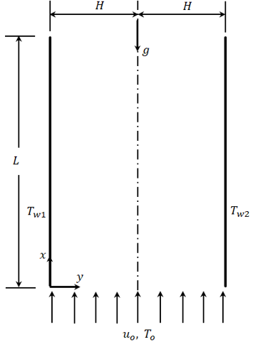
The problem geometry is as shown in Figure 1. A gas with uniform inlet conditions ($u=u_o, T=T_o$) enters a parallel plate channel of gap width 2H, and length L with constant wall temperatures in a gravity opposed flow configuration.
Figure 1. Schematic of the problem geometry: Gravity opposed flow
The problem formulation and governing equations are detailed below, assuming steady, incompressible flow with constant thermo-physical gas properties, and including viscous dissipation and flow work in the model. The complete model is stated below, including both the continuity and the transverse momentum equations. The solutions are then obtained for the case of an infinitely long channel.
$\frac{\partial u}{\partial x}+\frac{\partial v}{\partial y}=0$ (1)
$\begin{aligned} \rho\left(u \frac{\partial u}{\partial x}+v \frac{\partial u}{\partial y}\right) & =-\frac{\partial p}{\partial x}+\mu\left(\frac{\partial^2 u}{\partial x^2}+\frac{\partial^2 u}{\partial y^2}\right) + \left(\frac{T}{T_o}-1\right) \rho g\end{aligned}$ (2)
$\rho\left(u \frac{\partial v}{\partial x}+v \frac{\partial v}{\partial y}\right)=-\frac{\partial p}{\partial y}+\mu\left(\frac{\partial^2 v}{\partial x^2}+\frac{\partial^2 v}{\partial y^2}\right)$ (3)
$\begin{gathered}\rho c_p\left(u \frac{\partial T}{\partial x}+v \frac{\partial T}{\partial y}\right)=k\left(\frac{\partial^2 T}{\partial x^2}+\frac{\partial^2 T}{\partial y^2}\right)+\mu \phi \\ +\beta T\left(u \frac{\partial p}{\partial x} v \frac{\partial p}{\partial y}\right)\end{gathered}$ (4)
where, $\phi$ is the viscous dissipation term given as:
$\phi=2\left[\left(\frac{\partial u}{\partial x}\right)^2+\left(\frac{\partial v}{\partial y}\right)^2\right]+\left(\frac{\partial u}{\partial y}+\frac{\partial v}{\partial x}\right)^2$ (5)
and $\beta$ is the coefficient of thermal expansion.
Using the following dimensionless variables,
$\xi=x / D_h, \quad \eta=y / D_h$ (6)
$U=u / u_o, V=v / u_o, P=p /\left(\rho u_o^2\right), \theta=T / T_o$ (7)
where, $D_h$ is the hydraulic diameter given as:
$D_h=4 H$ (8)
the governing Eqs. (1)–(4) in dimensionless form become:
$\frac{\partial U}{\partial \xi}+\frac{\partial V}{\partial \eta}=0$, (9)
$\begin{gathered}\operatorname{Re}\left(U \frac{\partial U}{\partial \xi}+V \frac{\partial U}{\partial \eta}\right) =-\operatorname{Re} \frac{\partial P}{\partial \xi}+\left(\frac{\partial^2 U}{\partial \xi^2}+\frac{\partial^2 U}{\partial \eta^2}\right)+\frac{\operatorname{Re}}{F r^2}(\theta-1)\end{gathered}$ (10)
$\operatorname{Re}\left(U \frac{\partial V}{\partial \xi}+V \frac{\partial V}{\partial \eta}\right)=-\operatorname{Re} \frac{\partial P}{\partial \eta}+\left(\frac{\partial^2 V}{\partial \xi^2}+\frac{\partial^2 V}{\partial \eta^2}\right)$
$\begin{gathered}\operatorname{Pe}\left(U \frac{\partial \theta}{\partial \xi}+V \frac{\partial \theta}{\partial \eta}\right)=\frac{\partial^2 \theta}{\partial \xi^2}+\frac{\partial^2 \theta}{\partial \eta^2}+(\gamma-1) \operatorname{Pr} M_o^2 \Phi +(\gamma-1) \operatorname{Pe} M_o^2\left(U \frac{\partial P}{\partial \xi}+V \frac{\partial P}{\partial \eta}\right) \theta\end{gathered}$ (12)
where,
$\begin{aligned} & \operatorname{Re}=\frac{\rho u_o D_h}{\mu}, M_o=\frac{u_o}{\sqrt{\gamma R T_o}}, \gamma=\frac{c_p}{c_v}, \\ & \operatorname{Pr}=\frac{\mu c_p}{k}, F r=\frac{u_o}{\sqrt{g D_h}}, \operatorname{Pe}=\operatorname{Re} \cdot \operatorname{Pr}\end{aligned}$ (13)
$\Phi=2\left[\left(\frac{\partial U}{\partial \xi}\right)^2+\left(\frac{\partial V}{\partial \eta}\right)^2\right]+\left(\frac{\partial U}{\partial \eta}+\frac{\partial V}{\partial \xi}\right)^2$ (14)
The term multiplying the viscous dissipation and the flow work terms in the energy Eq. (12) is essentially the Brinkman number, which is the ratio of frictional heating to heat transfer by conduction.
$(\gamma-1) M_o^2 P r=\frac{\mu u_o^2}{k T_o} \equiv B r$
The ratio $R e / F r^2$ appearing in the momentum Eq. (10) is rewritten as:
$\frac{R e}{F r^2}=\frac{\rho u_o D_h}{\mu} \cdot \frac{g D_h}{u_o^2}=\frac{\rho g D_h^2}{\mu u_o}=\frac{Gravity ~forces}{Viscous ~forces \times Intertial ~forces}$
The Ratio $\operatorname{Re} / F r^2$ is somehow similar to the Grashof to Reynolds number ratio (Gr/Re) normally used in mixed and natural convection analysis. Using the parameters implemented in this work, the ratio (Gr/Re) can be written as:
$\frac{G r}{R e}=\frac{\rho g \beta \Delta T D_h^2}{\mu u_o}$ (15)
while using (14) in the buoyancy term of Eq. (10) leads to:
$\begin{gathered}\frac{\operatorname{Re}}{\operatorname{Fr}^2}(\theta-1)=\frac{\rho g D_h^2}{\mu u_o}\left(\frac{T}{T_o}-1\right)=\frac{\rho g \beta\left(T-T_o\right) D_h^2}{\mu u_o} =\frac{\rho g \beta \Delta T D_h^2}{\mu u_o}\end{gathered}$ (16)
which is the same expression as (Gr/Re) above. The difference between the above two expressions is that $\Delta T$ in (Gr/Re) is constant that can be defined as $\Delta T=T_w-T_o$, while $\Delta T$ in the buoyancy term is a variable ($\Delta T=T-T_o$).
2.1 Boundary conditions
The slip flow regime is defined in the Knudsen number range: $0.01<K n<0.1$ [17], where the Knudsen number $K n$ is defined as the ratio of the mean free path to the hydraulic diameter;
$K n=\frac{\lambda}{D_h}$ (17)
The gas taken in this study is air, entering the channel at atmospheric pressure and $T_o=300 \mathrm{~K}$ with the corresponding thermo-physical properties [18]:
$\begin{gathered}R=287 \mathrm{~J} / \mathrm{kg} . \mathrm{K}, \quad v=1.589 \times 10^{-5} \mathrm{~m}^2 / \mathrm{s} \\ \rho=1.1614 \mathrm{~kg} / \mathrm{m}^3 \\ c_p=1007 \mathrm{~J} / \mathrm{kg} . \mathrm{K}, \quad k=0.0263 \mathrm{~W} / \mathrm{m} . \mathrm{K} \\ \operatorname{Pr}=0.707\end{gathered}$
The relation between Reynolds, Knudsen and Mach numbers is given as [17]:
$K n=\sqrt{\frac{\pi \gamma}{2}} \frac{M_o}{R e}$ (18)
The Knudsen number with the given air properties can be calculated using Eq. (18). For even a transitional microchannel with $D_h=10 \mu \mathrm{~m}: K n=6.787 \times 10^{-3}<0.01$. Therefore, slip effects may be considered as negligibly small, and the noslip boundary conditions are used in this analysis. Also, thermal creep effects are zero for an infinitely long channel $(\partial T / \partial x \rightarrow 0)$ with both pressure work and viscous dissipation included in the model [19]. Therefore, the boundary|conditions for this case are simplified to read:
$\begin{gathered}u(x, 0)=u(x, 2 H)=0, T(x, 0)=T_{w 1} \\ T(x, 2 H)=T_{w 2}\end{gathered}$ (19)
$\begin{gathered}U(0)=U(1 / 2)=0, \theta(0)=\theta_{w 1}, \\ \theta(1 / 2)=\theta_{w 2}\end{gathered}$ (20)
2.2 Forced convection in an infinitely long channel
The governing equations of forced convection in an infinitely long channel can be derived from Eqs. (10) and (12), with $\beta=1 / T$:
$\frac{d^2 U}{d \eta^2}=\operatorname{Re} \frac{d P}{d \xi}$ (21)
$\begin{aligned} & \frac{d^2 \theta}{d \eta^2}+(\gamma-1) M_o^2 \operatorname{Pr}\left(\frac{d U}{d \eta}\right)^2 +(\gamma-1) M_o^2 \operatorname{Pr} R e \frac{d P}{d \xi} U=0\end{aligned}$ (22)
The solution of the above equations is:
$U(\eta)=\frac{1}{4} R e \frac{d P}{d \xi}\left(2 \eta^2-\eta\right)$ (23)
Using Eq. (23) and the fact that:
$U_m=\frac{u_m}{u_o}=2 \int_0^{1 / 2} U d \eta=1.0$ (24)
The pressure gradient is given as:
$\operatorname{Re} \frac{d P}{d \xi}=-48$ (25)
and the solution of the energy Eq. (22) is:
$\begin{gathered}\theta(\eta)=\theta_{w 1}+2\left(\theta_{w 2}-\theta_{w 1}\right) \eta -72(\gamma-1) M_o^2 \operatorname{Pr}\left[\eta^2-4 \eta^3+4 \eta^4\right]\end{gathered}$ (26)
The Darcy friction factor is defined as:
$f=\frac{8 \tau_w}{\rho u_o^2}$ (27)
The wall shear stress is evaluated using Eq. (23), and Eq. (27) reduces to the well defined result on both walls:
$f.Re=96$ (28)
The mean temperature is given by:
$\theta_m=2 \int_0^{1 / 2} U \theta d \eta$ (29)
Using Eqs. (23), (25), (26) in Eq. (29), the mean temperature is evaluated as:
$\theta_m=\frac{1}{2}\left(\theta_{w 1}+\theta_{w 2}\right)-\frac{27}{35}(\gamma-1) M_o^2 P r$ (30)
The dimensional and dimensionless wall heat fluxes at both walls are as given in Eqs. (31)–(33) below.
$q_{w 1}=-k\left(\frac{\partial T}{\partial y}\right)_{y=0}, q_{w 2}=-k\left(\frac{\partial T}{\partial y}\right)_{y=2 H}$ (31)
$Q_{w 1}=\frac{q_{w 1} D_h}{k T_o}=\frac{h D_h}{k}\left(\theta_{w 1}-\theta_m\right)=-\left(\frac{\partial \theta}{\partial \eta}\right)_{\eta=0}$ (32)
$Q_{w 2}=\frac{q_{w 2} D_h}{k T_o}=\frac{h D_h}{k}\left(\theta_m-\theta_{w 2}\right)=-\left(\frac{\partial \theta}{\partial \eta}\right)_{\eta=1 / 2}$ (33)
Using Eqs. (26) and (30), the dimensionless wall heat transfer rates are:
$Q_{w 1}=2\left(\theta_{w 1}-\theta_{w 2}\right)$ (34)
$Q_{w 2}=2\left(\theta_{w 1}-\theta_{w 2}\right)$ (35)
and the Nusselt number at both walls can be evaluated as:
$N u_1=\frac{h D_h}{k}=-\frac{1}{\left(\theta_{w 1}-\theta_m\right)}\left(\frac{\partial \theta}{\partial \eta}\right)_{\eta=0}=\frac{Q_{w 1}}{\theta_{w 1}-\theta_m}$ (36)
$N u_2=\frac{h D_h}{k}=-\frac{1}{\left(\theta_m-\theta_{w 2}\right)}\left(\frac{\partial \theta}{\partial \eta}\right)_{\eta=\frac{1}{2}}=\frac{Q_{w 2}}{\theta_m-\theta_{w 2}}$ (37)
$N u_1=\frac{140\left(\theta_{w 1}-\theta_{w 2}\right)}{35\left(\theta_{w 1}-\theta_{w 2}\right)+54(\gamma-1) M_o^2 P r}$ (38)
$N u_2=\frac{140\left(\theta_{w 1}-\theta_{w 2}\right)}{35\left(\theta_{w 1}-\theta_{w 2}\right)-54(\gamma-1) M_o^2 P r}$ (39)
The following special cases can be concluded from Eqs. (38) and (39):
Case 1: For $\theta_{w 1} \neq \theta_{w 2}$, with no viscous dissipation and flow work (i.e., $\left.(\gamma-1) M_o^2 P r=0\right)$):
$N u_1=N u_2=4$ (40)
In agreement with the result reported in the study of Shah and London [20] for $\theta_{w 1} \neq \theta_{w 2}$ and neglecting both the viscous dissipation and flow work.
Case 2: For $\theta_{w 1}=\theta_{w 2}$: with viscous dissipation and flow work:
$N u_1=N u_2=0$ (41)
as reported in the previous study [19].
2.3 Mixed convection in an infinitely long channel
The governing equations of mixed convection in an infinitely long channel can be deduced from Eqs. (10) and (12):
$\frac{d^2 U}{d \eta^2}+\frac{\operatorname{Re}}{F r^2}(\theta-1)=\operatorname{Re} \frac{d P}{d \xi}$ (42)
$\begin{gathered}\frac{d^2 \theta}{d \eta^2}+(\gamma-1) M_o^2 \operatorname{Pr}\left(\frac{d U}{d \eta}\right)^2+(\gamma-1) M_o^2 \operatorname{Pr} \operatorname{Re} \frac{d P}{d \xi} U \theta =0\end{gathered}$ (43)
Eqs. (42) and (43) involve three unknowns: $U, \theta, d P / d \xi$, and are solved numerically by iteration, subject to the condition given by Eq. (24):
The numerical solution procedure of Eqs. (42) and (43) is summarized as follows:
1. Assume $d P / d \xi$ (a good starting point can be taken from the forced convection case (Eq. (25));
$d P / d \xi=-48 / \operatorname{Re}$
2. Solve Eqs. (42) and (43) for the velocity and temperature fields.
3. Calculate the mean velocity Um and check if condition (24) is satisfied with a specified tolerance. If not satisfied, the assumed $d P / d \xi$ is modified and iteration continues up to convergence.
The governing Eqs. (42) and (43) are solved by iteration, using the DBVPFD subroutine of the IMSL library. The subroutine uses a variable order, variable step size finite difference method with deferred corrections. A step size of
5 × 10⁻⁵ is used, with a convergence criterion of 10-10. The forced convection governing equations are solved analytically, and the analytical solutions are used as a comparison with mixed convection, in order to investigate the conditions under which the buoyancy effects are considerable. This comparison also serves as a verification of the accuracy of the numerical solutions as the buoyancy effects vanish. Solutions are obtained for channel hydraulic diameters ranging from 10 to 10000 $\mu \mathrm{m}$, with a range of inlet velocities from 0.01 to 10 m/s. This study therefore covers micro-, mini- and conventional channels. All the results presented pertain to the asymmetric constant wall temperatures $\theta_{w 1}=1.1, \theta_{w 2}=0.9$, unless otherwise stated.
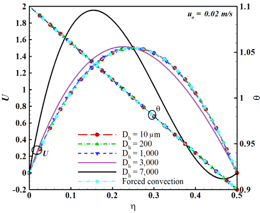
Figure 2. Velocity and temperature profiles with inlet velocity $u_o=0.02 \mathrm{~m} / \mathrm{s}$ in micro-, mini- and conventional channels
Figure 2 shows the velocity and temperature profiles in channels with different hydraulic diameters and inlet velocity $u_o=0.02 \mathrm{~m} / \mathrm{s}$. For Dh = 10, 200, and 1000 μm, the velocity profiles almost coincide with that for forced convection, indicating that the buoyancy is insignificant for $D_h \leq 1000 ~\mu \mathrm{m}$. The velocity peak starts shifting from the channel centerline ($\eta=0.25$) towards the left side of the channel (the hotter wall), as clearly seen in the plots for Dh = 3,000 and 7,000 μm. This indicates that the buoyancy effect progressively increases with increasing hydraulic diameter, where a secondary velocity peak and reverse flow may appear near the right side of the channel (the colder wall), as is clear in the case with $D_h = 7,000 ~\mu \mathrm{m}$ of Figure 2. The buoyancy effect on the temperature distribution seems insignificant, as all the temperature profiles coincide with that corresponding to forced convection.
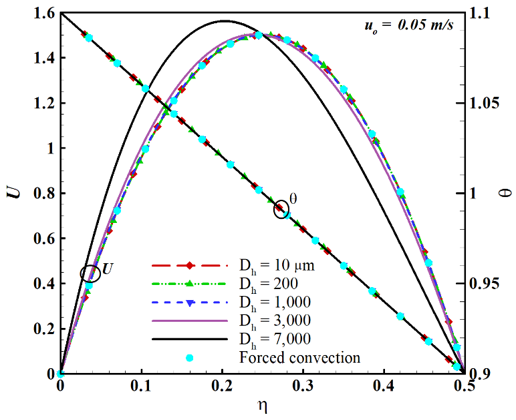
Figure 3. Velocity and temperature profiles with inlet velocity $u_o=0.05 \mathrm{~m} / \mathrm{s}$ in micro-, mini- and conventional channels
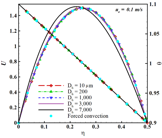
Figure 4. Velocity and temperature profiles with inlet velocity $u_o=0.1 \mathrm{~m} / \mathrm{s}$ in micro-, mini- and conventional channels
Figures 3 and 4 also show the velocity and temperature profiles in channels with different hydraulic diameters, but with velocity $u_o=0.05 \mathrm{~m} / \mathrm{s}$ and $0.1 \mathrm{~m} / \mathrm{s}$, respectively. Figures 2 to 4 show that buoyancy effects become significant with decreasing the inlet velocity and increasing the channel hydraulic diameter.
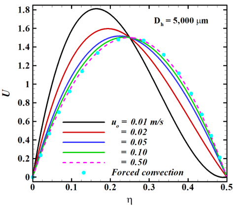
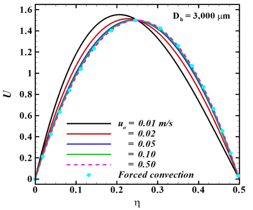
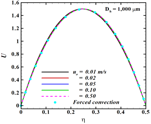
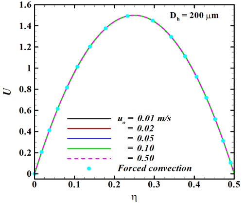
Figures 5–8 present the velocity profiles in channels with $D_h = 5000, 3000, 1000 and 200 ~\mu \mathrm{m}$, respectively, for different inlet velocities. The same conclusions drawn from Figures 2–4 can also be seen in Figures 5–8, in terms of the relation between the buoyancy effect and the inlet velocity as well as the channel hydraulic diameter. The results presented in Figures 2–8 also demonstrate the accuracy of the numerical solutions obtained, in the sense that the numerical solutions obtained for mixed convection approach the analytical solution of the forced convection case as the buoyancy effect becomes vanishingly small, where the numerical solution coincides with the analytical solution for forced convection.
Figure 5. Velocity profiles in a conventional channel with $D_h=5000 ~\mu \mathrm{m}$ for different values of inlet velocity
Figure 6. Velocity profiles in a minichannel with $D_h=3000 ~\mu \mathrm{m}$ for different values of inlet velocity
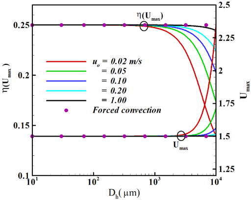
The loci of the maximum velocity $\left(\eta\left(U_{\text {max }}\right)\right)$ in channels with 10 $\mu \mathrm{m} \leq D_h \leq 10000 ~\mu \mathrm{m}$ together with the corresponding maximum velocity are shown in Figure 9, for different values of inlet velocity. For forced convection in channel flow, the maximum velocity is located at the channel centerline (i.e., at $\eta=0.25$) and $U_{\text {max}}=1.5$ as shown in Figure 9, regardless of the channel diameter or the inlet velocity. The locus of the maximum velocity progressively shifts towards the left (hotter) wall with increasing hydraulic diameter and decreasing inlet velocity, indicating the increasing buoyancy effect with increasing $D_h$ and decreasing $u_o$. The results presented in Figure 9 also demonstrate that buoyancy effects become vanishingly small for around $D_h< 500 ~\mu \mathrm{m}$ for the inlet velocity range shown.
Figure 7. Velocity profiles in a minichannel with $D_h=1000 ~\mu \mathrm{m}$ for different values of inlet velocity
Figure 8. Velocity profiles in a microchannel with $D_h=200 \mu \mathrm{m}$ for different values of inlet velocity
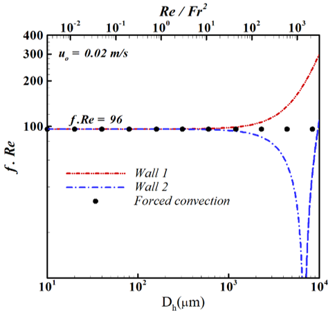
As is seen in the momentum Eq. (42), the buoyancy term includes the dimensionless parameter $\left(R e / F r^2\right)$. It is therefore appropriate to measure the significance of the buoyancy in terms of this dimensionless parameter, rather than the dimensional parameters $D_h$ and $u_o$, hence generalizing the conclusions discussed above in terms of a dimensionless parameter. The variation of the friction factor ($f . R e$) with both $D_h$ and the corresponding $\mathrm{Re} / \mathrm{Fr}^2$ is shown in Figure 10 for an inlet velocity of $u_o=0.02 \mathrm{~m} / \mathrm{s}$.
The well-established result for forced convection in a parallel plate channel $(f . R e=96)$ is also presented on the same plot. Figure 10 shows that the friction factor in mixed convection on both channel walls takes on almost the same value as the forced convection case for $D_h<500 ~\mu \mathrm{m}$, corresponding to $\mathrm{Re} / \mathrm{Fr}^2<10$ with minimal buoyancy effect. The friction factor starts increasing on the hotter wall (wall 1) with increasing $D_h$ and $\operatorname{Re} / F r^2$, due to the increasing buoyancy effect, which results in a higher velocity gradient at the wall. The friction factor on the colder wall (wall 2) decreases with increasing $D_h$ and $\operatorname{Re} / F r^2$ then starts increasing again for $D_h>6800, R e / F r^2>1430$. This is due to the fact that as buoyancy strengthens, the velocity peak shifts toward the hot wall, and the velocity gradient increases on the hot wall (wall 1), but decreases on the cold wall (wall 2). When buoyancy becomes very strong ($D_h>6800, R e /F r^2>1430$), the velocity profile exhibits a secondary peak and the flow reverses direction near the cold wall, causing the velocity gradient to increase again, therefore the friction factor.
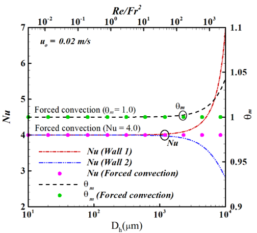
The variation of the Nusselt number and the mean temperature with the hydraulic diameter and the corresponding $\mathrm{Re} / \mathrm{Fr}^2$ is depicted in Figure 11 for an inlet velocity $u_o=$ 0.02 m/s.
Figure 9. Loci of the maximum velocity and corresponding maximum velocity in channel flow as functions of the hydraulic diameter and inlet velocity
Figure 10. Variation of the friction factor with channel hydraulic diameter and the parameter $\operatorname{Re} / F r^2$ for $u_o=0.02 \mathrm{~m} / \mathrm{s}$
Figure 11. Variation of the Nusselt number and the mean temperature with channel hydraulic diameter and the corresponding parameter $\operatorname{Re} / F r^2$ for $u_o=0.02 \mathrm{~m} / \mathrm{s}$
Both the Nusselt number and the mean temperature in mixed convection remain almost constant at the values corresponding to the forced convection case ($N u=4, \theta_m=$ 1) for $D_h<500 ~\mu \mathrm{m}$ and $\operatorname{Re} / F r^2<10$. Therefore, buoyancy effect on Nusselt number and consequently on heat transfer is negligible when $R e / F r^2<10$. Buoyancy effect on heat transfer becomes increasingly more significant as $D_h$ increases beyond $500 ~\mu \mathrm{m}$ and $R e / F r^2$ increases above 10 . Figure 11 also shows that both $N u$ on the hotter wall and $\theta_m$ continually increase with increasing $R e / F r^2$ due to increased buoyancy effects, while $N u$ on the colder wall decreases due to the effect of buoyancy on the temperature gradient at the wall.
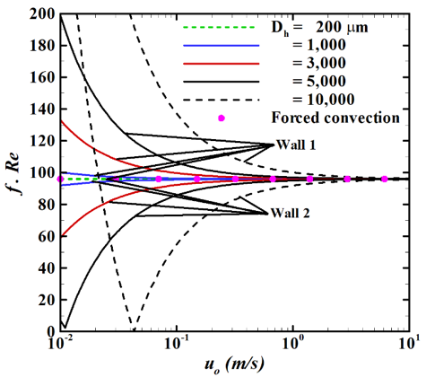
Figure 12. Variation of the friction factor with the inlet velocity in micro-, mini- and conventional channels
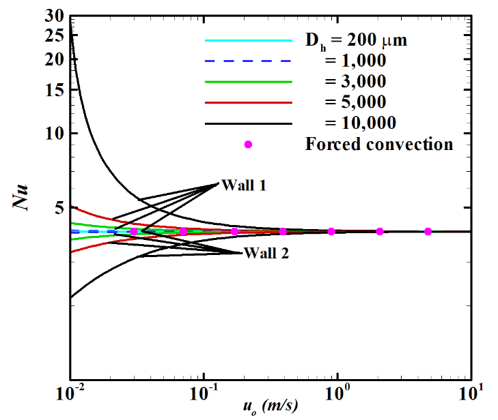
Figures 12 and 13, respectively, demonstrate the variation of the friction factor and Nusselt number with the channel inlet velocity in micro-, mini- and conventional channels. These results show that the lower the inlet velocity and the higher the channel hydraulic diameter, the higher the difference between forced and mixed convection, hence the higher effect of buoyancy. As can be clearly seen in Figures 12 and 13, the friction factor and Nusselt number in a microchannel with Dh = 200 μm are almost the same as for forced convection (i.e., $f . R e \cong 96, N u \cong 4.0)$ for $0.01 \leq u_o \leq 10 \mathrm{~m} / \mathrm{s}$, indicating that buoyancy effects are negligible.
Figure 13. Variation of the Nusselt number with the inlet velocity in micro-, mini- and conventional channels
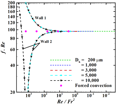
Figure 14. Variation of the friction factor with the $\mathrm{Re} / \mathrm{Fr}^2$ in micro-, mini- and conventional channels corresponding to Figure 12
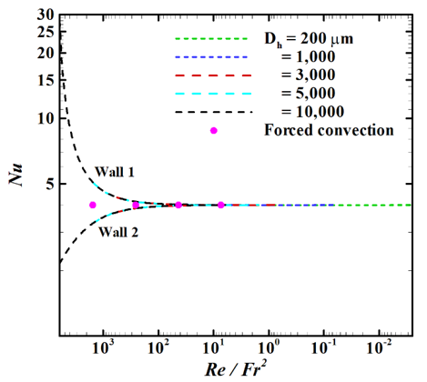
Figures 12 and 13 also show that with inlet velocity $u_o>$ $3 \mathrm{~m} / \mathrm{s}$, the buoyancy effects on fluid flow and heat transfer are negligible even in conventional channels ($D_h=5000,1000$ $\mu \mathrm{m}$). The variations of the friction factor and Nusselt number with the parameter $R e / F r^2$ corresponding to Figures 12 and 13 are presented in Figures 14 and 15, respectively. For $\mathrm{Re} / \mathrm{Fr}^2<10$, Figures 14 and 15 confirm that the friction factor and Nusselt number in mixed convection are almost the same as those with forced convection; hence, as previously concluded, the buoyancy effects on fluid flow and heat transfer can be considered as negligible when $\operatorname{Re} / F r^2<10$, and it becomes progressively more and more significant for $\operatorname{Re} / F r^2>10$.
Figure 15. Variation of Nusselt number with $\operatorname{Re} / F r^2>10$ in micro-, mini- and conventional channels corresponding to Figure 13
This proposed criterion can be validated using the similarity between the normally used mixed convection parameter $\operatorname{Gr} / \operatorname{Re}$ (Eq. (15)) and the buoyancy term of the momentum equation (Eq. (16)) involving the proposed parameter $R e / F r^2$. Evaluating the buoyancy term of the momentum equation at the hot wall, with $R e / F r^2=10$:
$\frac{R e}{F r^2}\left(\theta_{w 1}-1\right)=\frac{\rho g D_h^2}{\mu u_o}\left(\frac{T_{w 1}}{T_o}-1\right)=10 \times(1.1-1)=1$
From Eqs. (15) and (16) and the above result:
$\frac{G r}{R e} \equiv \frac{R e}{F r^2}\left(\theta_{w 1}-1\right)=\frac{\rho g D_h^2}{\mu u_o}\left(\frac{T_{w 1}}{T_o}-1\right)=\frac{\rho g \beta \Delta T D_h^2}{\mu u_o}=1$
Therefore, the criterion $\mathrm{Re} / \mathrm{Fr}^2>10$ is equivalent to $G r / R e>1$, in agreement with the conditions reported in [9] for buoyancy significance in mixed convection.
Mixed convection in infinitely long parallel plate micro-, mini- and conventional channel gas flow is analyzed numerically in this work. The model includes both viscous dissipation and flow work, and uses the Boussinesq approximation for the body force in the momentum equation. The governing equations are solved using the DBVPFD subroutine of the IMSL library with a very low step size of $5 \times 10^{-5}$ and a convergence criterion of 10-10 to ensure a high level of accuracy. The forced convection governing equations are also solved analytically, and comparisons between forced and mixed convection are presented to investigate the significance of buoyancy on fluid flow and heat transfer characteristics. The comparison verifies the accuracy of the numerical results in the limiting case of negligible buoyancy effects. Results are presented for wide ranges of channel hydraulic diameters and inlet velocities. The variations of the Darcy friction factor and Nusselt number with the dimensionless parameter $Re / F r^2$ are also presented and discussed.
The results show that buoyancy effects on fluid flow and heat transfer in channel flow become more significant with decreasing the inlet velocity and increasing the channel hydraulic diameter. Decreasing the inlet velocity and/or increasing the hydraulic diameter leads to an increase in the dimensionless parameter $Re / F r^2=g D_h^2 /\left(v u_o\right)$. The variations of the friction factor and Nusselt number with the parameter $Re / F r^2$ are therefore conveniently presented to conclude a criterion for the significance of buoyancy as related to this dimensionless parameter. The results show that buoyancy effects in parallel plate channels become increasingly more significant as the dimensionless parameter $\operatorname{Re} / F r^2$ increases, and cannot be ignored for around $Re / F r^2>10$. Quantitatively, for a microchannel with Dh = 100 μm, the inlet velocity $u_o$ should be much less than about 0.0025 m for the buoyancy effect to be considerable, while for a microchannel with Dh = 10 μm, buoyancy effects can be considerable when the inlet velocity $u_o$ is much less than about 0.0063 mm/s. Consequently, the buoyancy effects on fluid flow and heat transfer characteristics in microchannel gas flow may be considered as negligibly small and can be ignored for typical values of inlet velocity (higher than 0.01 m/s). Practically, the results presented provide insights for designing and optimizing channel-based thermal systems. The suggested criterion based on $Re / F r^2$ serves as a straightforward tool for predicting when buoyancy effects start to matter and determines if mixed convection modeling is necessary. This is especially relevant for microchannel heat sinks and compact heat exchangers, where neglecting buoyancy could result in incorrect predictions of heat transfer rates and pressure drops. Importantly, these results indicate that natural convection alone is unlikely to effectively drive flow in microchannels and small mini-channels (for example, 200 μm < $D_h$ < 500 μm) due to the low velocities required for buoyancy to be significant. This finding directly impacts the design of passive cooling systems, where relying on buoyancy-driven flow at the microscale may not be feasible. Furthermore, using $Re / F r^2$ as a common parameter allows for direct comparisons across various channel scales, offering a more uniform framework than traditional Grashof-based methods.
This study is carried out with isothermal wall conditions. Such conditions have different applications, particularly in heat exchangers, electronic cooling, and manufacturing processes. An extension of this work for future studies is the investigation of buoyancy significance in micro-, mini- and conventional channel gas flow, with other wall boundary conditions, such as isoflux and convection boundary conditions, in addition to conjugate heat transfer effects. Such conditions also have many different applications in thermal engineering. Future research may also expand this analysis by including additional physical effects, such as compressibility, rarefaction, and varying thermophysical properties. It could also validate the proposed criterion against experimental data. Exploring transient conditions and three-dimensional geometries would further enhance the applicability of these findings.
|
$c_p$ |
Specific heat at constant pressure ($\mathrm{J} / \mathrm{kg} \cdot \mathrm{K}$) |
|
$D_h$ |
Hydraulic diameter ($=4 H$) |
|
Fr |
Froude number ($u_o / \sqrt{g D_h}$) |
|
g |
Gravitational acceleration $=9.81 \mathrm{~m} / \mathrm{s}^2$ |
|
Gr |
Grashof number |
|
H |
Channel half-gap width (m) |
|
k |
Thermal conductivity ($\mathrm{W} / \mathrm{m} \cdot \mathrm{K}$) |
|
Kn |
Knudsen number |
|
Mo |
Mach number at channel inlet ($=u_o / \sqrt{\gamma R T_o}$) |
|
$p$ |
Pressure (N/m2) |
|
P |
Dimensionless Pressure ($=p /\left(\rho u_o^2\right)$) |
|
Pe |
Peclet number ($=\operatorname{Re} \cdot \operatorname{Pr}$) |
|
Pr |
Prandtl number ($=\mu c_p / k$) |
|
qw |
Wall heat flux (W/m2) |
|
R |
Gas constant ($\mathrm{J} / \mathrm{kg} \cdot \mathrm{K}$) |
|
Re |
Reynolds number ($=u_o D_h / v$) |
|
Nu |
Nusselt number |
|
T |
Temperature (K) |
|
u |
Velocity component in the x- direction (m/s) |
|
v |
Velocity component in the y- direction (m/s) |
|
uo |
Inlet velocity (m/s) |
|
U |
Dimensionless velocity ($U=u / u_o$) |
|
Um |
Dimensionless mean velocity |
|
Greek symbols |
|
|
$\mu$ |
Dynamic viscosity (N $\cdot s / \text{m}^2$) |
|
$\tau_w$ |
Wall shear stress (N/m2) |
|
$v$ |
Kinematic viscosity (m2/s) |
|
$\rho$ |
Density (kg/m3) |
|
$\beta$ |
Coefficient of thermal expansion (K-1) |
|
$\gamma$ |
Specific heat ratio ($\gamma=c_p / c_v$) |
|
$\phi$ |
Viscous dissipation function |
|
$\Phi$ |
Dimensionless viscous dissipation function |
|
$\xi$ |
Dimensionless coordinate in the longitudinal direction |
|
$\eta$ |
Dimensionless coordinate in the transverse direction |
|
$\theta$ |
Dimensionless temperature ($=T / T_o$) |
|
$\theta_o$ |
Dimensionless inlet temperature (=1) |
|
$\theta_w$ |
Dimensionless wall temperature ($=T_w / T_o$.) |
|
Subscripts |
|
|
w |
Wall |
|
m |
Mean value |
|
o |
Inlet conditions |
[1] Kandlikar, S.G., Garimella, S., Li, D.Q., Colin, S., King, M.R. (2006). Heat Transfer and Fluid Flow in Minichannels and Microchannels. Amsterdam, Elsevier. https://doi.org/10.1016/B978-0-08-044527-4.X5000-2
[2] Amran, M.F., Sultan, S.M., Tso, C.P. (2024). A comprehensive review of mixed convective heat transfer in tubes and ducts: Effects of Prandtl number, geometry, and orientation. Processes, 12(12): 2749. https://doi.org/10.3390/pr12122749
[3] Zhang, J.Q., Zou, Z.P., Fu, C. (2023). A review of the complex flow and heat transfer characteristics in microchannels. Micromachines, 14(7): 1451. https://doi.org/10.3390/mi14071451
[4] Avramenko, A.A., Tyrinov, A.I., Shevchuk, I.V., Dmitrenko, N.P., Kravchuk, A.V., Shevchuk, V.I. (2017). Mixed convection in a vertical flat microchannel. International Journal of Heat and Mass Transfer, 106: 1164-1173. https://doi.org/10.1016/j.ijheatmasstransfer.2016.10.096
[5] Avramenko, A.A., Tyrinov, A.I., Shevchuk, I.V., Dmitrenko, N.P., Kravchuk, A.V., Shevchuk, V.I. (2017). Mixed convection in a vertical circular microchannel. International Journal of Thermal Sciences, 121: 1-12. https://doi.org/10.1016/j.ijthermalsci.2017.07.001
[6] Avramenko, A.A., Kovetska, Y.Y., Shevchuk, I.V., Tyrinov, A.I., Shevchuk, V.I. (2018). Mixed convection in vertical flat and circular porous microchannels. Transport in Porous Media, 124: 919-941. https://doi.org/10.1007/s11242-018-1104-4
[7] Niazmand, H., Rahimi, B. (2012). Mixed convective slip flows in a vertical parallel plate microchannel with symmetric and asymmetric wall heat fluxes. Transactions of the Canadian Society for Mechanical Engineering, 36(3): 207-218. https://doi.org/10.1139/tcsme-2012-0015
[8] Avci, M., Aydin, O. (2007). Mixed convection in a vertical parallel plate microchannel. ASME Journal of Heat Transfer, 129(2): 162-166. https://doi.org/10.1115/1.2422741
[9] Ghiaasiaan, S.M. (2018). Convective Heat and Mass Transfer, 2nd Edition. CRC Press, Taylor & Francis Group, NW. https://doi.org/10.1201/9781351112758
[10] Buonomo, B., Manca, O. (2010). Natural convection slip flow in a vertical microchannel heated at uniform heat flux. International Journal of Thermal Sciences, 49(8): 1333-1344. http://doi.org/10.1016/j.ijthermalsci.2010.03.005
[11] Jha, B.K., Aina, B., Joseph, S.B. (2014). Natural convection flow in a vertical microchannel with suction/injection. In Proceedings of the Institution of Mechanical Engineers, Part E: Journal of Process Mechanical Engineering, 228(3): 171-180. https://doi.org/10.1177/0954408913492719
[12] Gourari, S., Mebarek-Oudina, F., Hussein, A.K., Kolsi, L., Hassen, W., Younis, O. (2019). Numerical study of natural convection between two coaxial inclined cylinders. International Journal of Heat and Technology, 37(3): 773-779. https://doi.org/10.18280/ijht.370314
[13] Abdulameer, Y.A., Al-Saif, A.J. (2023). FLT-HPM for two-dimensional transient natural convection in a horizontal cylindrical concentric annulus. Power Engineering and Engineering Thermophysics, 2(3): 120-138. https://doi.org/10.56578/peet020301
[14] Jha, B.K., Musa, M.K., Ajibade, A.O. (2024). Natural convection flow in a thermally stratified fluid through an asymmetrically heated and cooled vertical channel with anisotropic porous material. Power Engineering and Engineering Thermophysics, 3(2): 116-133. https://doi.org/10.56578/peet030204
[15] Chae, M.S., Chung, B.J. (2014). Laminar mixed-convection experiments in horizontal pipes and derivation of a semi-empirical buoyancy coefficient. International Journal of Thermal Sciences, 84: 335-346. http://doi.org/10.1016/j.ijthermalsci.2014.06.007
[16] Mohammed, H.A., Salman, Y.K. (2007). Combined natural and forced convection heat transfer for assisting thermally developing flow in a uniformly heated vertical circular cylinder. International Communications in Heat and Mass Transfer, 34(4): 474-491. http://doi.org/10.1016/j.icheatmasstransfer.2007.01.001
[17] Karniadakis, G., Beskok, A., Aluru, N. (2005). Microflows and Nanoflows: Fundamentals and simulation. Springer New York, NY. https://doi.org/10.1007/0-387-28676-4
[18] Incropera, F.P., DeWitt, D. (2007). Fundamentals of Heat and Mass Transfer (6th Edition). John Wiley & Sons. https://www.scirp.org/reference/referencespapers?referenceid=904176.
[19] Ou, J.W., Cheng, K.C. (1973). Effects of pressure work and viscous dissipation on Graetz problem for gas flows in parallel-plate channels. Wärme - und Stoffübertragung, 6: 191-198. https://doi.org/10.1007/BF02575264
[20] Shah, R.K., London, A.L. (1978). Laminar Flow Forced Convection in Ducts (Supplement 1 to Advances in Heat Transfer). Academic Press. https://www.scirp.org/reference/referencespapers?referenceid=1283822.