Amal Oliwie
© 2026 The author. This article is published by IIETA and is licensed under the CC BY 4.0 license (http://creativecommons.org/licenses/by/4.0/).
OPEN ACCESS
This study numerically investigates the thermo-hydraulic performance of three hybrid nanofluids, namely Al2O3–CuO/water Al2O3–TiO2/water, and Al2O3–ZnO/water nanofluid flowing through a dimpled circular pipe equipped with a twisted tape insert under turbulent flow conditions. A validated Computational Fluid Dynamics (CFD) model was employed to analyze the effects of Reynolds number (Re), nanoparticles volume fraction, twist ratio, and dimple geometry on heat transfer and flow behavior under constant heat flux boundary conditions. The simulations were performed for Re ranging from 12,000 to 30,000. The results indicate that the combined use of twisted tape inserts, dimpled geometry, and hybrid nanofluids significantly enhances the thermal performance compared with a plain pipe. The maximum Nusselt number (Nu) enhancement reached approximately 61.8% at high Re, while the thermo-hydraulic performance evaluated using the PEC improved by up to 45% compared to the smooth pipe. Although the friction factor increased by approximately 38% due to the induced swirl flow and surface modifications, the overall thermohydraulic performance remained favorable. The proposed combined enhancement approach demonstrates strong potential for application in compact and high-efficiency heat exchanger systems.
hybrid nanofluids, twisted tape insert, dimpled pipe, Nusselt number, friction factor, thermo-hydraulic performance, Computational Fluid Dynamics
Heat transfer enhancement plays a vital role in improving the efficiency of thermal systems. Passive techniques such as twisted tape inserts and surface dimples have proven effective in enhancing convective heat transfer. Hybrid nanofluids further improve thermal conductivity. However, limited studies investigate the combined effect of twisted tape, dimpled surfaces, and hybrid nanofluids simultaneously [1]. To achieve greater useful heat, the pipe can be combined with turbulators. Techniques for improving productivity can be classified as active or passive, depending on whether they utilize external forces [2]. Altering the properties of the carrier fluid by mixing it with nano-sized particles can lead to higher performance. The primary concept behind using nanomaterials is to address the limitations of conventional fluids in heat absorption [3, 4].
The continuous development of technology and the increasing generation of thermal energy have shown important limitations in traditional heat exchanger designs and base fluids. Such limitations limit the effective heat transfer in compact systems. Therefore, there is a great demand for new methods to enhance the heat transfer and to keep the necessary thermal performance during the operation [5].
Improving the working fluid's thermal conductivity is one of the most crucial of these techniques, and nanofluids as a novel, extremely effective energy transfer medium offer enormous promise for use in a variety of industries [6, 7]. Heat exchanger efficiency can be increased using either passive or active methods [8]. To enable better heat transfer performance, these techniques take advantage of basic phenomena like increasing contact area, encouraging turbulence, altering material microstructures, and creating vortex forms, among others [9]. Using passive techniques accomplishes reliability objectives and enhances the thermal performance and effectiveness of management systems in a range of applications [10].
In such approaches, enhancing the thermal conductivity of the working fluid is essential. Nanofluids, as a novel and highly effective energy transfer medium, have shown significant potential for a wide range of thermal engineering applications. In addition, various active and passive approaches can enhance the efficiency of the heat exchanger [11, 12].
The existing literature can be broadly classified into four categories for successfully identifying the research gap and confirming the originality of the present study, including (1) studies on hybrid nanofluids, (2) studies on dimpled surfaces, (3) studies on twisted tape inserts, and (4) studies on combined heat transfer enhancement techniques. A detailed review of these classifications is given below to clarify the current state of knowledge and the shortcomings of previous studies.
1.1 Hybrid nanofluids
Nanofluids were introduced to improve the thermal performance of heat transfer systems by enhancing the thermophysical properties of conventional working fluids. They are produced by dispersing nanofluids with characteristic dimensions below 100nm into a base fluid. Various highly conductive materials, such as different metals, copper, metal oxides, and carbon nanotubes, have been extensively employed for this purpose due to their ability to improve thermal conductivity and heat transfer characteristics [13]. Numerous investigations have demonstrated the effectiveness of nanofluids in enhancing thermal performance under different operating conditions [14]. More recently, hybrid nanofluids have emerged as an advanced class of heat transfer fluids. These fluids consist of two or more nanoparticle types suspended within a base fluid, enabling the combination of desirable physical and chemical properties from different materials [15, 16].
Owing to their improved thermophysical characteristics, hybrid nanofluids have attracted considerable attention in a variety of engineering applications, including industrial processes, transportation systems, biomedical devices, marine structures, and thermal energy systems. Although significant progress has been achieved in this field, most previous studies have focused on relatively simple flow configurations. Consequently, the thermo-hydraulic performance of hybrid nanofluids in compound enhancement techniques involving both twisted tape inserts and dimpled surfaces remains insufficiently investigated.
1.2 Dimpled pipe /dimpled surfaces
An investigation of thermal flow in dimple pipes demonstrated improved heat transfer in heat exchangers featuring inner wall dimples. Several researchers utilized Computational Fluid Dynamics (CFD) to do three-dimensional calculations to see how dimple pitch, diameter, number, and distance by using Taguchi and response surface as optimization methods. Performance improved by about 35.8% to 36.2% compared to smooth pipes, with a performance evaluation factor (PEF) greater than one [17]. The impact of artificial roughness on dimpled tubes is examined. The study utilizes results related to thermal conduction and pressure reduction [18]. Findings indicate that the roughness of the artificial shape significantly affects pressure drop characteristics more than it influences heat transfer enhancement. Additionally, the shape notably impacts the transition of the pipe to the turbulent flow regime [19]. The simulation focused on the enhancement of vortex heat in turbulent flow within a narrow parallel channel using an inclined oval dimple design. This type of dimple may result in increased pressure losses in the channel, as well as improved heat transfer [20].
In previous studies, the efficiency of heat transfer has been increased by dimpled surfaces due to vortex formation and boundary layer breakdown. However, these studies were mostly limited to conventional working fluids and did not consider the interaction between dimple-induced vortices, twisted tape swirl flow, and the properties of hybrid nanofluids.
1.3 Twisted tape inserts
Twisted tape inserts are a prevalent technique for inducing turbulence near the wall, as they provide an internal swirling flow that extends the fluid flow direction within the pipeline, enhancing fluid dynamics mixing and diminishing the thermal boundary area, hence enhancing the rate of convective heat transfer [21].
Passive heat transfer enhancement techniques have been investigated to improve the thermo-hydraulic performance of heat exchangers and internal flow systems. Among these techniques, wire-coil inserts have shown great potential for the enhancement of turbulence intensity and heat transfer rates. Previous studies have shown that the thermal enhancement performance of the coiled-wire inserts is highly dependent on the geometrical parameters such as the gap spacing and pitch ratio. The optimum configuration was obtained at a pitch ratio of 1 and a gap distance of 1 mm, resulting in an overall thermal performance improvement of about 50% [6].
Swirl flow and increased fluid mixing can be produced by twisted-tape inserts, which are also commonly used. Some studies reported significant enhancement of Nusselt number (Nu) and thermal performance factor for the combination of nanofluids with twisted tapes. In particular, hybrid nanofluids with Al2O3 and CuO nanoparticles showed better heat-transfer features than conventional fluids and mono nanofluids, especially at moderate nanoparticle concentrations and optimum twist ratios [22-24]. The use of twisted tapes and magnetic hybrid nanofluids has enhanced the thermo-hydraulic performance of solar thermal systems. Reported results demonstrated significant improvements in the performance evaluation criterion over a wide range of Reynolds number (Re) by combining passive enhancement devices with advanced working fluids [25].
Previous studies have proven that the combination of twisted tapes and rib-type surface modifications can provide a significant thermo-hydraulic performance enhancement. The twisted tapes are mainly responsible for the mixing of fluid and the generation of swirl, while the V-ribs are mainly responsible for the increase in the intensity of turbulence in the near-wall region. It was reported that the combination of these two enhancement mechanisms led to better heat-transfer augmentation as compared to the use of any of the two techniques alone [26, 27]. Compound enhancement techniques like ribs, wire coils, winglets and twisted tapes have been studied more recently. The investigations revealed that the combined use of several enhancement devices usually provides a larger heat transfer augmentation than the application of a single technique. For example, the simultaneous use of wire coils and twisted tapes resulted in higher Nu and thermal enhancement factors than those obtained by using each insert individually [28, 29]. But most of the published studies have been on smooth tubes or conventional enhancement configurations. The synergistic effect of the dimpled tube geometries with twisted-tape inserts and hybrid nanofluids under turbulent flow conditions is still not well studied. Hence, there is a need for further investigations to elucidate the thermo-hydraulic performance of such compound enhancement systems [28, 29].
1.4 Combined enhancement techniques
To expand our investigation into a numerical analysis of elevated Re within the tube, we aim to address the limitations of the experimental setup at higher mass flow rates. This approach underscores the uniqueness of our research compared to previous studies, as we conduct a numerical examination of the thermal-hydraulic performance enhanced by a pipe heat exchanger [30]. We utilize punched delta-winglet vortex generators (PDWVGs) as the insert device, which has the potential to enhance convective heat transfer. Our results are validated by comparing them with findings from our earlier experimental investigation [31]. The parameters varied in their study included the Re, pitch ratio, and open area ratio. They indicated that the most significant parameter was the open area ratio, which leads to a high thermal performance factor when it is elevated. The results related to thermal performance and friction coefficient demonstrate the impact of attack angles of 15°, 30°, and 45° at various blockage ratios on the winglet vortex generator insert [32]. The heat transfer and pressure drop in a pipe containing coiled wire positioned independently from the pipe wall were examined. Three distinct pitch ratios were utilized: P/D = 1, P/D = 2, and P/D = 3, along with two gap sizes of 1 mm (s = 1 mm) and 2 mm (s = 2 mm). The maximum overall thermal performance of 50% was achieved with the coiled wire at a pitch ratio of 1 and a wire diameter of 1 mm [33].
The use of dimple-based surface modification techniques to augment heat transfer in circular pipe has been investigated, revealing that vortex generation and turbulence intensification significantly enhance thermal performance under optimized geometric conditions [34].
Although several studies have examined combined passive enhancement techniques, most were conducted within relatively moderate Re ranges or employed conventional working fluids. Comprehensive investigations involving the simultaneous use of twisted tape inserts, dimpled pipe geometry, and hybrid nanofluids at high turbulent Re are still scarce in the available literature.
Table 1. Comparison of previous studies and research gap related to heat transfer enhancement techniques
|
Ref. |
Enhancement Technique |
Working Fluid |
Re |
Volume Fraction |
Method |
Performance Parameter |
Limitation Compared with Present Study |
|
[16, 17] |
Dimpled tube |
Water |
1000–2000 |
_ |
CFD |
Nu, f |
Only dimpled geometry no inserts or nanofluid |
|
[18-20] |
Dimpled surfaces |
water |
Moderate |
|
CFD |
Nu, f |
Conventional fluids only |
|
[21] |
Fixed ring inserts and twisted tape |
Al₂O₃–CuO/water |
6000–14,000 |
0.3%, 0.6%, 0.9% |
CFD |
Nu, PEC |
No dimpled geometry |
|
[22] |
Twisted tape |
Al2O3–CuO/water |
850–1500 |
1.8 |
Experimental |
Nu, PEC |
No dimpled tube |
|
[23, 24] |
Twisted tape |
TiO2/water |
4500 |
|
Experimental |
Nu, PEC |
Low Re |
|
[25] |
Twisted tape |
Magnetic hybrid nanofluid |
24000–6000 |
|
Experimental |
PEC |
No dimpled geometry |
|
[26, 27] |
V-cut twisted tape |
water |
4000–10,000 |
|
Experimental |
PEC |
No dimpled geometry |
|
[28] |
Combined nanofluids with wire coil inserts |
TiO2 -SiO2 nanofluids |
2300–12000 |
0.5–3.0% |
Experimental |
PEC |
No dimpled geometry |
|
[31, 32] |
Delta-winglet vortex generators |
water |
9100–17,400. |
|
Experimental |
Nu, f, PEC |
No dimpled geometry |
|
[33] |
Circular tubes with twisted tape wire coil |
water |
Moderate |
|
Numerical, Experimental |
Nu, f |
No dimpled geometry |
|
[34] |
Dimple geometry (surface concavity) |
water |
3000–20000 |
|
CFD |
PEC |
No twisted tape |
|
Present study |
Dimpled tube+ Twisted tape+ hybrid nanofluids |
Al2O3+CuO/water Al2O3+TiO2/water Al2O3+ZnO/water |
12,000–30,000 |
3% |
CFD |
Nu, f, PEC |
High-Re Combined enhancement |
Note: Re = Reynolds number; CFD = computational fluid dynamics; Nu = Nusselt number; f = friction factor; PEC = performance evaluation criterion; Al₂O₃ = aluminum oxide; CuO = copper oxide; TiO₂ = titanium dioxide; SiO₂ = silicon dioxide; ZnO = zinc oxide.
Based on the literature summarized in Table 1, it can be observed that previous studies mainly focused on individual enhancement techniques, including twisted tape inserts, dimpled surfaces, or hybrid nanofluids. Although significant improvements in heat transfer have been reported, most investigations examined these techniques independently or under relatively moderate Re conditions. Studies combining passive enhancement devices with advanced working fluids remain limited, particularly for dimpled tubes equipped with twisted tape inserts. Furthermore, the thermo-hydraulic behavior of hybrid nanofluids under high Re turbulent flow has not been comprehensively investigated. Therefore, the present study aims to address this research gap by numerically evaluating the combined influence of dimpled surfaces, twisted tape inserts, and hybrid nanofluids on heat transfer, friction factor, performance evaluation criterion, and entropy generation over a Re range of 12,000–30,000.
The primary objective of this research is to investigate the synergistic thermo-hydraulic enhancement achieved through the combined utilization of hybrid nanofluids, twisted tape inserts, and dimpled pipe geometry under turbulent flow conditions. Particular attention is given to the trade-off between heat transfer enhancement and pressure drop through a comprehensive performance evaluation.
The novelty of this work lies in the combined investigation of hybrid nanofluids and compound heat transfer enhancement techniques inside a pipe. Unlike previous studies that focused on either twisted tape inserts or dimpled surfaces separately, the present study integrates both techniques in a single configuration to intensify turbulence and heat transfer. In addition, the use of hybrid nanofluids further improves the thermal properties of the working fluid. The main novel aspects of this research can be summarized as follows:
This study presents an integrated investigation of heat transfer enhancement in a twisted tape -inserted dimpled pipe using hybrid nanofluid, focusing on the combined and interactive effects of surface modification and working fluid enhancement rather than treating them separately.
The simultaneous use of twisted tape inserts and dimpled pipe walls together with hybrid nanofluids is analyzed to enhance turbulence intensity, secondary flow structure and thermal mixing, which has been limitedly examined in previous numerical studies.
The analysis is conducted for a relatively high turbulent flow regime (Re = 12,000 – 30,000), extending the applicability of results to more realistic industrial turbulent flow conditions.
A comprehensive assessment is carried out based on Nu, friction factor, and thermal performance criteria (PEC), providing a complete understanding of the heat transfer -pressure drop trade-off.
The study provides physical insights into the interaction between swirl flow generated by twisted tape and secondary vortices induced by dimples, offering practical guidelines for optimizing an enhanced heat transfer system.
2.1 Physical model
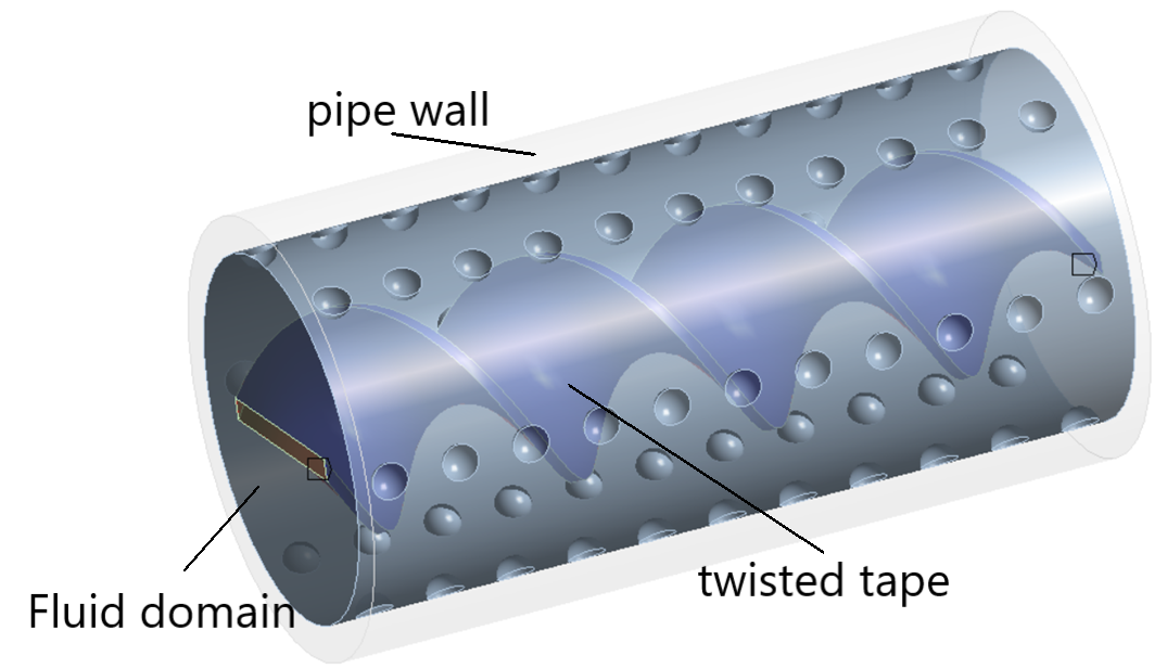
The physical model considered in the present study consists of a copper dimpled circular pipe equipped with an internal aluminum twisted tape insert to enhance thermo-hydraulic performance under turbulent flow conditions. Water-based hybrid nanofluids, including Al2O3–CuO/water, Al2O3–ZnO/water, and Al2O3–TiO2/water, were employed as working fluids and modeled using a single-phase approach.
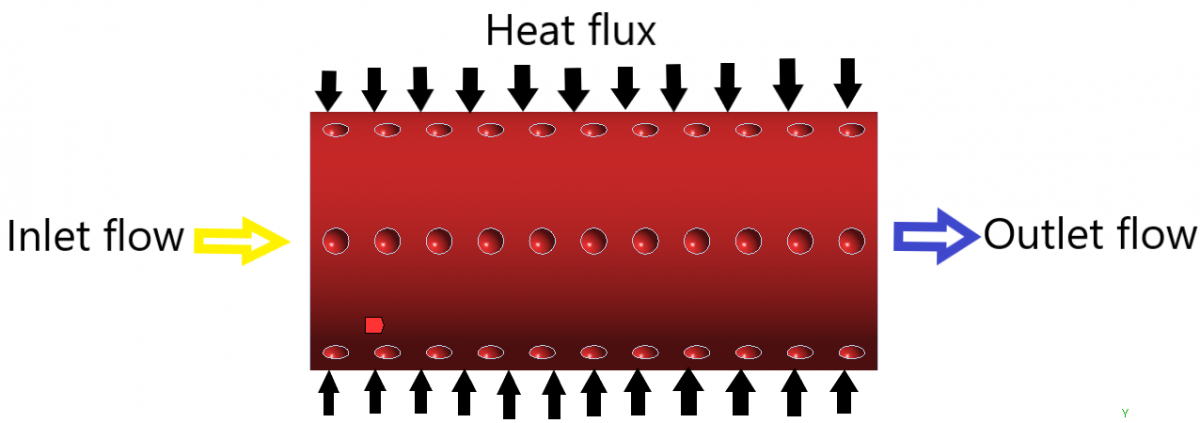
A uniform heat flux was applied to the outer surface of the pipe wall, while the inlet fluid temperature was maintained at 300 K. The flow regime was controlled using Re ranging from 12,000 to 30,000. The geometrical configuration of the dimpled pipe and twisted tape insert was adopted from previous validated studies. Figure 1 illustrates the computational domain and boundary conditions used in the numerical simulation, while the main geometrical and operating parameters are summarized in Table 2.
Figure 1. Computational domain and boundary conditions of the physical model
Table 2. Physical model parameters and operating conditions of the present study
|
Parameters |
Value |
Unit |
|
Pipe length |
609.6 |
mm |
|
Inner diameter (Di) |
16.69 |
mm |
|
Outer diameter (Do) |
17.78 |
mm |
|
Inlet Temperature |
300 |
K |
|
Number of dimple lines |
6 |
– |
|
Nanoparticles volume fraction (ɸ) |
3 |
% |
|
Dimple diameter |
2.5 |
mm |
|
Dimple depth |
1 |
mm |
|
Dimple pitch distance |
10 |
mm |
|
Twisted tape material |
Aluminum |
– |
|
Twisted tape dimension |
30 × 3 |
mm |
|
Number of twists |
4 |
– |
|
Twist Ratio |
0.5 |
– |
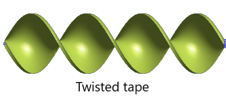
Figure 2 shows the computational domain of the dimpled pipe with a twisted tape insert.
The chosen ranges are intended to reflect practical limits that are commonly encountered in real-world applications. Values outside these limits are likely to lead to geometries that are not manufacturable or compatible with operational constraints. This has also been used in previous studies with similar justifications [35, 36].
(a) Detailed geometry of the dimpled pipe and twisted tape insert
(b) Twisted tape
Figure 2. Computational domain of the dimpled pipe with twisted tape insert
2.2 Mathematical formulation
The governing equations include continuity, momentum, and energy equations under steady, incompressible turbulent flow conditions. The realizable k-epsilon turbulence model was applied [35].
Equation of continuity flow:
$\frac{\partial}{\partial x}\left(\rho u_i\right)=0$ (1)
The components of velocities in three directions X, Y, and Z, are indicated by u, v, and w, respectively.
Equation of momentum flow:
$\frac{\partial}{\partial x_i}\left(\rho u_i u_j\right)=-\frac{\partial p}{\partial x_i}+\frac{\partial y}{\partial x_j}\left[\mu\left(\frac{\partial u_i}{\partial x_j}+\frac{\partial u_j}{\partial x_i}\right)-\frac{2}{3} \mu \frac{\partial u_i}{\partial x_i}+\delta_{i j}\right]$ (2)
Equation of energy flow:
$\begin{gathered}\frac{\partial}{\partial x_i}\left(u_i(\rho E+p)\right) =-\frac{\partial y}{\partial x_i}\left[\left(\lambda+\frac{C p}{P r_t}\right)-\frac{\partial T}{\partial x_J}+\mu\left(T_{i j}\right)_{e f f} \right]\end{gathered}$ (3)
The symbols for fluid density, velocity, and pressure were $\rho, u$ and $p$.
The realizable k-epsilon turbulence model is widely used for analyzing internal turbulent flows characterized by strong swirl and curvature effects, particularly in configurations such as twisted tape and dimpled pipe [35].
$\frac{\partial}{\partial x_i}\left(\rho k u_j\right)=\frac{\partial p}{\partial x_i}\left[\left(\mu+\frac{\mu_t}{\sigma_k}\right) \frac{\partial k}{\partial x_i}\right]+\Gamma-\rho \varepsilon$ (4)
The friction factor f is defined below in equation [12].
$f=\frac{2 \Delta p}{\rho u_i^2} \frac{D_h}{L}$ (5)
To determine the ‘Reynolds number (Re)’ [37].
${Re}=\frac{\rho u D_h}{\mu}$ (6)
$\mu, \rho$ and $D_h$ indicate the dynamic viscosity, density and pipe diameter respectively.
rate of heat was defined as [10]:
$q=m C p \Delta T$ (7)
Also, ‘Nusselt number (Nu)’ represents:
$N u=\frac{h D_h}{\lambda}$ (8)
When heat coefficient and thermal conductivity are represented by h and k.
The criteria of performance evaluation (PEC) are calculated as [12]:
$P E C=\frac{N u / N u_0}{\left(f / f_0\right)^{1 / 3}}$ (9)
Numerical simulations were carried out using ANSYS FLUENT 2025 R1 commercial software. A pressure-based solver with a pressure-velocity coupling algorithm was employed to solve the governing equations.
The gradients of diffusion terms were evaluated using the least-squares cell-based method. Spatial discretization of the momentum and energy equations was performed using a second-order upwind scheme. Convergence was assumed when the residuals of continuity, momentum, turbulent kinetic energy (k) and turbulent dissipation (ε) equations reached 10−6, while the energy equation reached 10−8. The standard wall function approach was adopted for near-wall treatment to avoid direct resolution of the viscous sublayer.
Accordingly, the dimensionless wall distance (y⁺) was maintained within the recommended range of 30–100 to ensure the validity of the wall function formulation.
The turbulence intensity (I) at the inlet was estimated using the widely accepted empirical correlations for fully developed pipe flow, as in the equation below [33]:
$\mathrm{I}=0.16 \mathrm{Re}^{-\frac{1}{8}}$ (10)
Based on the investigated Re range (12,000–30,000), the calculated turbulence intensity varied between approximately 4.4% and 4.9%.
The turbulence length scale was specified as (0.07Dh). These values are consistent with standard CFD practices for turbulent internal flow simulations and ensure the applicability of the selected turbulence model for the investigated dimpled pipe equipped with twisted tape inserts.
The suitability of the Realizable k–ε model for such complex geometries has been well established in previous studies, making it appropriate for predicting the flow and heat transfer characteristics in the present configuration.
Hybrid nanofluid properties were calculated using standard mixture models for density, specific heat, viscosity, and thermal conductivity. Three cases of mixtures (Al2O3-CuO/water, Al2O3-ZnO/water and Al2O3-TiO2/water) were indicated as a single phase in investigations in Table 3 and Table 4.
Table 3. Thermal properties of water and nanoparticles [20]
|
Properties |
Water |
Al2O3 |
CuO |
ZnO |
TiO2 |
|
$\rho\left({ }^{k g} / \mathrm{m}^3\right)$ |
998.2 |
3980 |
6400 |
5700 |
4250 |
|
$\mu$ (pa.s) |
0.001003 |
- |
- |
- |
- |
|
$\lambda$ hnf (W/m.k) |
0.6 |
40 |
76.5 |
60 |
11 |
|
Cp (J/kg.k) |
4182 |
765 |
535.6 |
500 |
710 |
Table 4. Thermal properties of hybrid nanofluids for $\phi$ =3%
|
Properties |
$\rho\left({ }^{k g} / \mathrm{m}^3\right)$ |
$\mu$ (pa.s) |
$\lambda$ (W/m.k) |
Cp (J/kg.K) |
|
Al2O3-CuO/water |
1123.95 |
0.001082 |
0.6539 |
3667.63 |
|
Al2O3-ZnO/water |
1113.45 |
0.001082 |
0.6536 |
3672.68 |
|
Al2O3-TiO2/water |
1091.7 |
0.001082 |
0.6518 |
3828.37 |
The effective thermal properties, such as specific heat capacity $C p_{n f}$, viscosity $\mu_{n f}$, density, and thermal conductivity $k_{n f}$ for the hybrid nanofluids were computed utilizing equations [20].
$\begin{gathered}\emptyset_{ {hybrid\ nanofluid }} =\emptyset_{ {hybrid\ nanoparticle } 1}+\emptyset_{{hybrid\ nanoparticles } 2}\end{gathered}$ (11)
$\rho_{h n f}=\rho_{n p 1} \emptyset_{n p 1}+\rho_{n p 2} \emptyset_{n p 2}+\left(1-\emptyset_{h n f}\right) \rho_{b f}$ (12)
$C_{p_{h n f}}=\frac{C p_{n p 1} \rho_1 \emptyset_{n p 1}+C p_2 \rho_2 \emptyset_{n p 2}+\left(1-\emptyset_{h n f}\right) \rho_f C p_{b f}}{\rho_{h n f}}$ (13)
$\mu_{h n f}=\frac{\mu_{b f}}{\left(1-\emptyset_{n p 1}-\emptyset_{n p 2}\right)^{2.5}}$ (14)
$\lambda_{h n f}=k_{b f} \frac{\left(\frac{\emptyset_{p 1} \lambda_1+\emptyset_{p 2} \lambda_2}{\emptyset_{ {total }}}\right)+2\left(\emptyset_{p 1} \lambda_{p 1}+\emptyset_{p 2} \lambda_{p 2}\right)+2 \lambda_{b f}-2 \emptyset_{ {total }} \lambda_{b f}}{\left(\frac{\emptyset_{p 1} \lambda_1+\emptyset_{p 2} \lambda_2}{\emptyset_{ {total }}}\right)+2 k_{b f}-\left(\emptyset_{p 1} \lambda_{p 1}+\emptyset_{p 2} \lambda_{p 2}\right)+\emptyset_{ {total }} \lambda_{b f}}$ (15)
3.1 Boundary conditions
The numerical simulations were performed under the boundary conditions summarized in Table 5. A uniform velocity profile was imposed at the inlet, while a pressure outlet condition was specified at the outlet. The pipe wall was assumed to be hydraulically smooth, and the Re was varied from 12,000 to 30,000.
Table 5. Boundary conditions and operating parameters used in the Computational Fluid Dynamics (CFD) simulations
|
Parameters |
Specification |
|
Working fluid |
Water and hybrid nanofluids |
|
Nanoparticles volume fraction |
3 vol% (1.5 vol%+1.5 vol%) |
|
Inlet temperature |
300 K |
|
Inlet boundary condition |
Uniform velocity inlet |
|
Outlet boundary condition |
Pressure outlet |
|
Wall condition |
No-slip, hydraulically smooth wall |
|
Wall thermal condition |
Constant heat flux (q") 3000 W/m2 |
|
Reynolds number (Re) range |
12,000-30,000 |
|
Flow regime |
Turbulent |
3.2 Mesh generation and grid independence
Grid Independence refers to the technique of improving results by progressively using smaller cell sizes in investigations. A calculation should yield accurate results, leading to a finer mesh, which is why this concept is termed grid independence. However, two significant challenges arise from this method. First, it can be quite challenging to achieve reliable results even with a single coarse mesh in some CFD software, leading to potential issues. Second, refining a mesh by a factor of two or more can be time-consuming. The Nu and friction factor were computed and analyzed in each case to establish grid independence, as shown in Figure 3. Based on the grid independence study, the mesh containing approximately 1.1 × 10⁶ elements was selected for all subsequent simulations. Further refinement to approximately 6.4 × 10⁶ elements resulted in a variation of less than 0.68%. in the average Nu, while substantially increasing the computational cost and memory requirements.
Table 6. Practical starting targets (cell counts)
|
Mesh Levels |
Number of Elements |
|
Coarse |
512039 |
|
Medium |
801231 |
|
Fine |
1,171,368 |
|
Very-Fine (optional) |
6,423,698 |
Table 7. Grid independence analysis showing the variation of average Nusselt number (Nu) and friction factor for different mesh densities
|
Mesh Level |
Average Nu |
Relative Error (%) |
Friction Factor |
Relative Error (%) |
|
Coarse |
64.85 |
– |
0.028999 |
– |
|
Medium |
64.95 |
0.154 |
0.02989 |
2.981 |
|
Fine |
65.70 |
1.142 |
0.03298 |
9.369 |
|
Very-Fine (optional) |
65.73 |
0.046 |
0.03325 |
0.812 |
Therefore, the selected mesh was considered to provide an appropriate balance between numerical accuracy and computational efficiency. The results obtained are presented in Table 6 and Table 7.
The numerical solution convergence was assessed using residual monitoring of the governing equations. The adopted convergence criteria are summarized in Table 8.
Table 8. Convergence criteria adopted in the present simulations
|
Equation |
Residual Criterion |
|
Continuity |
10-6 |
|
Momentum |
10-6 |
|
Turbulent kinetic energy (k) |
10-6 |
|
Turbulent dissipation rate ($\varepsilon$) |
10-6 |
|
Energy |
10-8 |
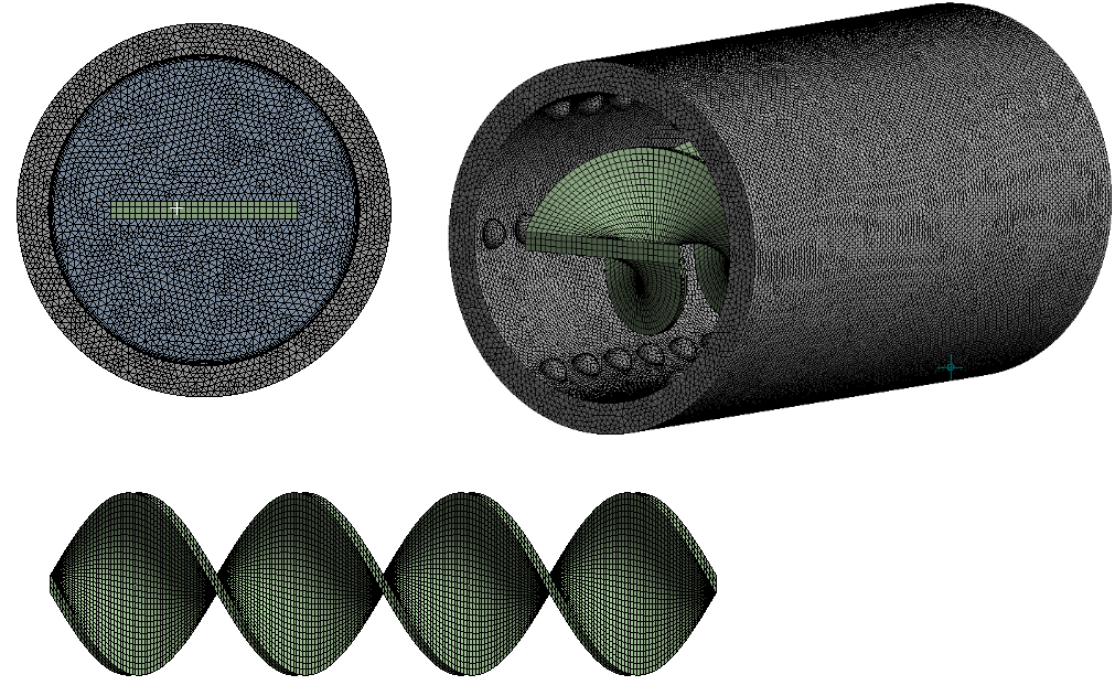
In addition to residual monitoring, the average Nu and friction factor were continuously monitored to ensure solution stability and convergence, as illustrated in Figure 4.
Figure 4. Mesh generation for the domain
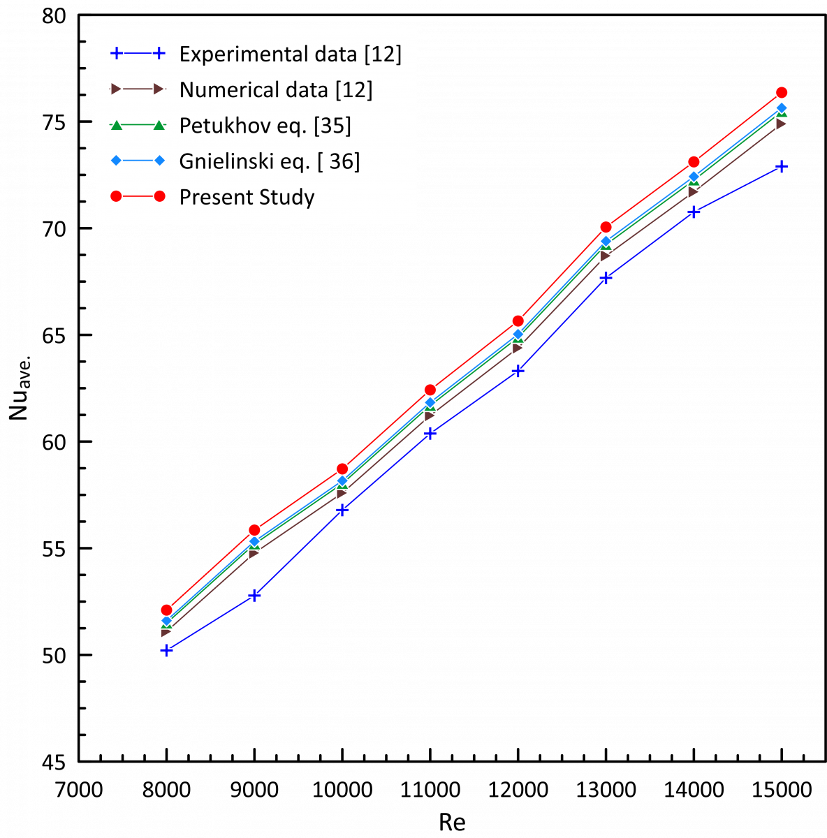
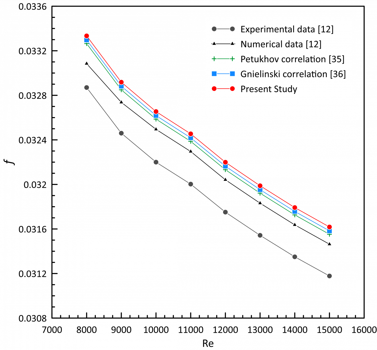
To ensure the reliability and accuracy of the present numerical investigation, a validation was carried out through comparison with well-established empirical correlations of turbulent flow in smooth pipes, as well as by previously published experimental and numerical works. The validation focused on two key parameters: (Nu) and (f), using conventional water as the base fluid in a smooth pipe configuration (without twisted tape and dimples) under the same boundary conditions.
For heat transfer validation, the Petukhov equation [35] and Gnielinski equation [36] were estimated. These equations are widely accepted for turbulent flow in smooth pipes with uniform heat flux. The numerical results of the present model showed very good agreement with the predicted values from this equation over the investigated Re range (8,000–15,000). The deviation between the numerical and theoretical results was found to be within approximately ±3.12–4.7%, which is considered acceptable for CFD simulations.
The Petukhov equation for (104 ˃ Re ˂ 5 × 10⁶) is computed as [35].
$N u=\frac{(f / 8) {Re}. {Pr}}{1.07+12.7(f / 8)^{1 / 2}\left({Pr}^{\frac{2}{3}}-1\right)}$ (16)
The Gnielinski equation for (1 × 10³ ˃ Re ˂ 5 × 10⁶) is estimated as [36]:
$\mathrm{Nu}=\frac{(\mathrm{f} / 8)(\mathrm{Re}-1000) \mathrm{Pr}}{1+12.7(\mathrm{f} / 8)^{1 / 2}\left({Pr}^{\frac{2}{3}}-1\right)}$ (17)
For friction factor validation, the well-known Blasius correlation and Petukhov correlation were used. The predicted friction factor values from the numerical model closely matched the Blasius equation, with deviations ranging between ±3.5–5.2% and ±2.98–4.7%. Furthermore, the enhanced pipe results were qualitatively compared with previously reported experimental and numerical data [12].
The comparison demonstrated good agreement between the present predictions and the reference results. The maximum deviations observed for the average Nu and friction factor were approximately 3.5% and 6.5%, respectively, as illustrated in Figure 5 and Figure 6. The agreement in trends and acceptable quantitative deviations confirms the validity of the numerical approach. Minor discrepancies can be attributed to differences in geometric configurations, turbulence modeling, mesh resolution, and assumptions of nanofluids thermophysical properties.
Figure 5. Validation of Nu for smooth pipe
Figure 6. Validation of the factor of friction in a smooth pipe
The validation results indicate that the present numerical model is sufficiently accurate and reliable for predicting the Nu and friction factor of hybrid nanofluids in twisted tape dimpled tubes and can be confidently used for further analysis and optimization.
The Petukhov correlation is determined as [35]:
$f=(0.790 \ln R e-1.64)^{-2}$ (18)
The Blasius correlation is computed as [36]:
$f=0.3164 R e^{-0.25}$ (19)
It is important to mention that the current validation against the correlations of Petukhov, Gnielinski, and Blasius is intended to verify the prediction of turbulent flow, heat transfer, and friction characteristics in a smooth tube. There were no direct experimental data available in the open literature for the exact configuration investigated in this work, namely a dimpled pipe equipped with twisted tape inserts and operating with hybrid nanofluids.
Therefore, the validation of the enhanced configuration relies on established numerical methodologies and thermophysical property correlations reported in previous studies. Future experimental investigations are recommended to further verify the numerical predictions under identical operating conditions.
The results are discussed, highlighting the interaction of swirl flow, vortices generated by the dimple, and properties of hybrid nanofluids, and their combined effect on thermo-hydraulic performance.
5.1 Velocity distribution analysis for different Reynolds number and hybrid nanofluids
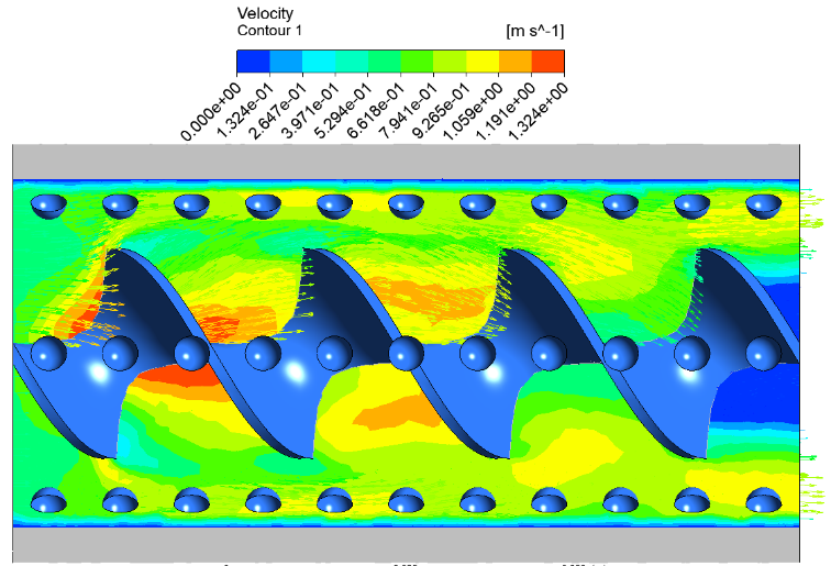
The velocity distribution in the twisted tape dimpled pipe is significantly influenced by the increase in (Re = 12,000 – 30,000) and the hybrid nanofluid type, namely (Al₂O₃-ZnO/water), (Al₂O₃-TiO₂/water), and (Al₂O₃-CuO/water). As the Re increases, the flow becomes more and more turbulent, the inertial forces become stronger and stronger, and better mixing in the fluid domain is achieved. It directly affects the velocity contours which tend to become more complex and non-uniform along the pipe length.
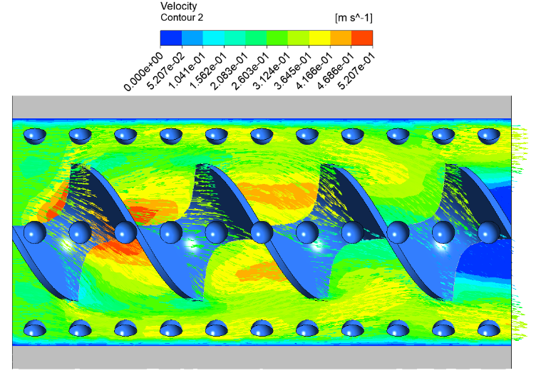
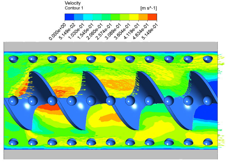
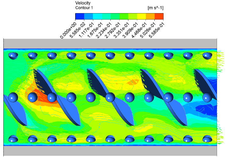
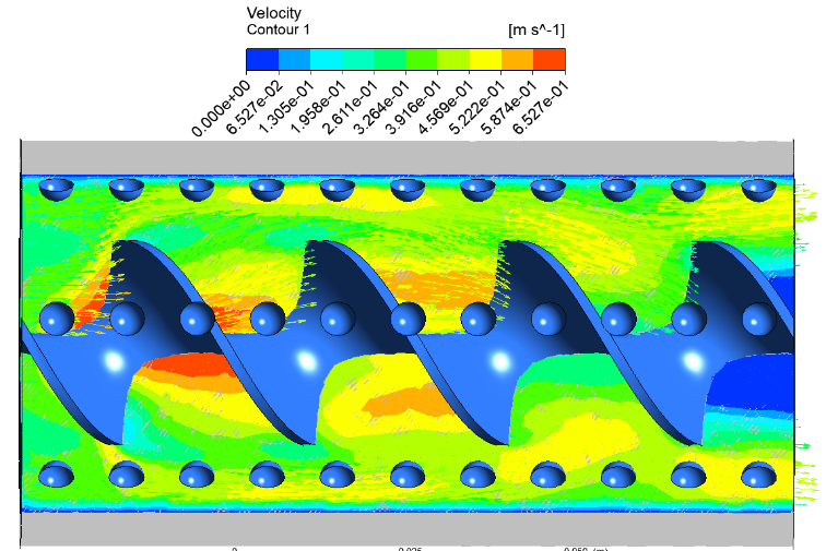
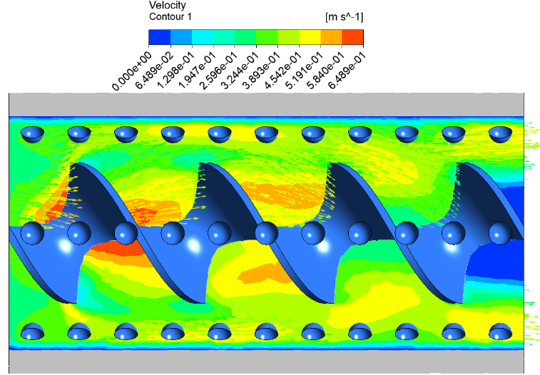
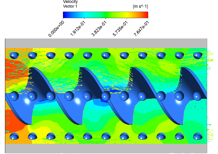
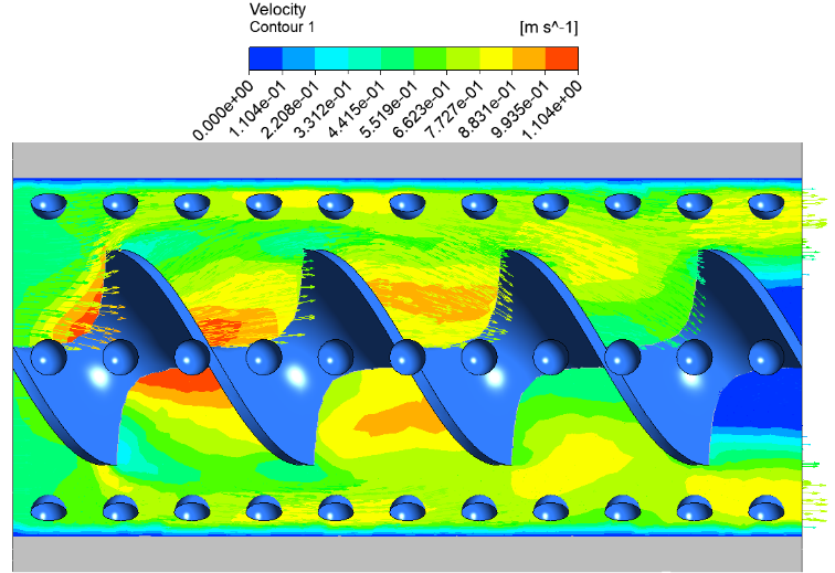
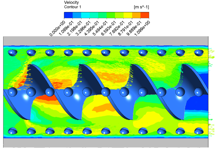
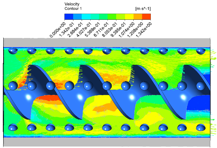
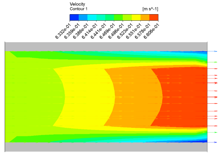
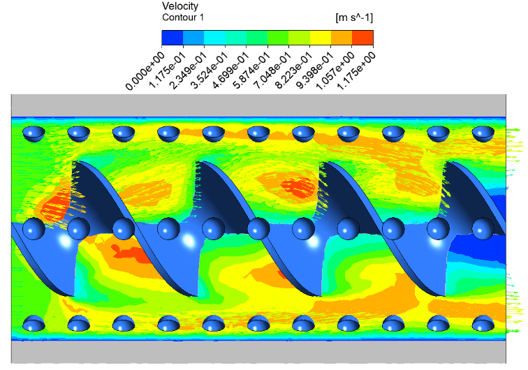
The velocity distribution is comparatively smoother at the lower (Re ≈ 12,000). The core region is more uniform with limited disturbance near the walls, as shown in Figure 7. The presence of twisted tape induces a mild swirling effect, creating helical flow patterns that slightly distort the axial velocity profile. The contour plot shows that the color distribution starts from the moderate shades (green to light yellow) at the inlet, which represents medium velocity magnitudes. Small low-velocity zones (blue regions) are seen near the pipe walls and in the dimples due to localized recirculation. As shown in Figure 8, when the Re increases to 15,000 and 20,000, the swirl intensity caused by the twisted tape is stronger, and the secondary flow structure is more obvious. The interaction of the dimpled surface with the swirling motion leads to the formation of localized vortices in the interior and downstream of each dimple cavity. These vortices enhance mixing of the fluid and disrupt the boundary layer, resulting in increased velocity gradients. This behavior is seen in the contour plots as an extension of the region of high velocities (yellow to orange colors) along the central core, whereas the recirculating regions of low velocities (dark blue) are more confined within the dimples.
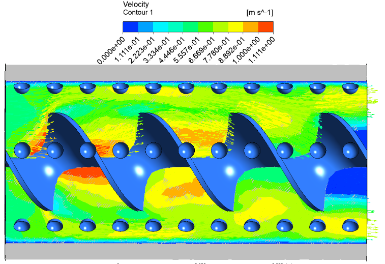
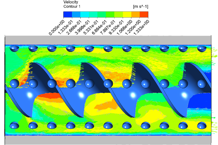
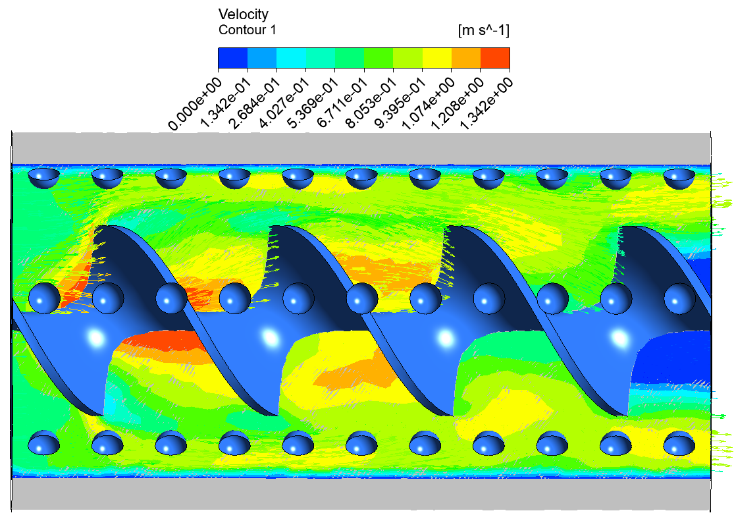
At high (Re = 25,000 and 30,000), the flow is highly turbulent, and velocity fluctuations are highly intensified by the combination of twisted tape and dimples, as shown in Figure 9 and Figure 10. The core region shows very high velocities (orange to red zones), indicating strong axial momentum, whereas the near-wall regions show rapid changes in velocity due to continuous vortex shedding and reattachment. The contour colors clearly show a transition from green at the inlet to red at the outlet, indicating the acceleration and redistribution of flow along the tube. Also, the dimples act as turbulence promoters, creating repetitive zones of flow detachment and reattachment that appear as alternating blue and yellow patches in the contour plots. Influence of the hybrid nanofluids aspects. The velocity distribution has obvious differences with the variations of the density and viscosity. The viscosity values for the (Al2O3- CuO/water) hybrid nanofluid are found to be generally slightly higher, which dampens the velocity magnitude near the walls but enhances the momentum diffusion, leading to a more uniform velocity gradient across the cross-section. On the other hand, (Al₂O₃-TiO₂/water) exhibits a balanced behavior between viscosity and density, resulting in stable and well-distributed velocity contours. On the other hand, (Al₂O₃-ZnO/water) has relatively higher peaks in velocity in the core region because of its relatively lower resistance to flow.
The evolution of the contour along the pipe shows a clear transition from cooler colors (blue and green) at low Re and near wall regions to warmer colors (yellow, orange and red) at higher Re and in the core flow. This shows the continuous improvement in flow mixing, turbulence intensity and velocity magnitude owing to the synergetic effects of twisted tape inserts, dimpled surfaces and hybrid nanofluids. This kind of behavior is very important for improving the heat transfer performance as the increased velocity gradient and turbulence are helpful for disruption of the thermal boundary layer.
5.2 Pressure distribution analysis under varying Reynolds number and hybrid nanofluids
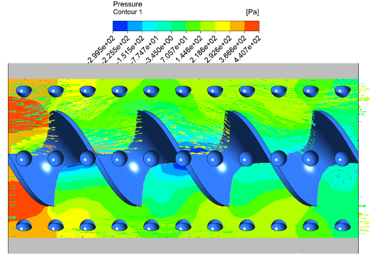
The pressure distribution inside the twisted tape dimpled pipe is strongly affected by the increase in (Re = 12,000 – 30,000) as well as the type of hybrid nanofluid used, namely (Al₂O₃-ZnO/water), (Al₂O₃-TiO₂/water), and (Al₂O₃-CuO/water). In general, the presence of twisted tape inserts and surface dimples introduces significant flow resistance, leading to a complex pressure field characterized by continuous pressure drop along the pipe and localized fluctuations due to secondary flow structures.
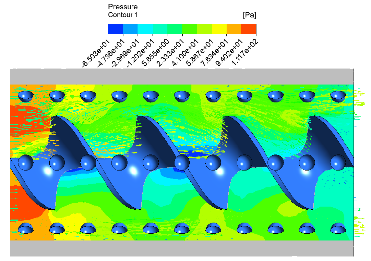
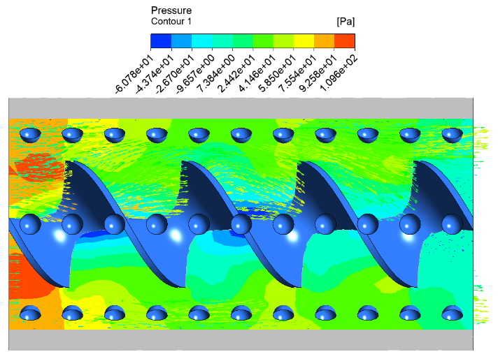
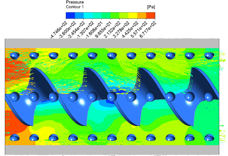
At the lowest (Re ≈ 12,000), the pressure distribution is rather smooth and decreases gently from inlet to outlet, as illustrated in Figure 11. The contour plot indicates that the high-pressure regions (red to orange colors) are concentrated near the inlet where the fluid first encounters the twisted tape obstruction. As the flow passes, the pressure drops gradually and then turns to yellow and green colors along the pipe length. Inside the dimples and in their wake, weak recirculation and flow separation lead to the development of localized low-pressure zones (blue regions), but these effects are contained at this flow condition.
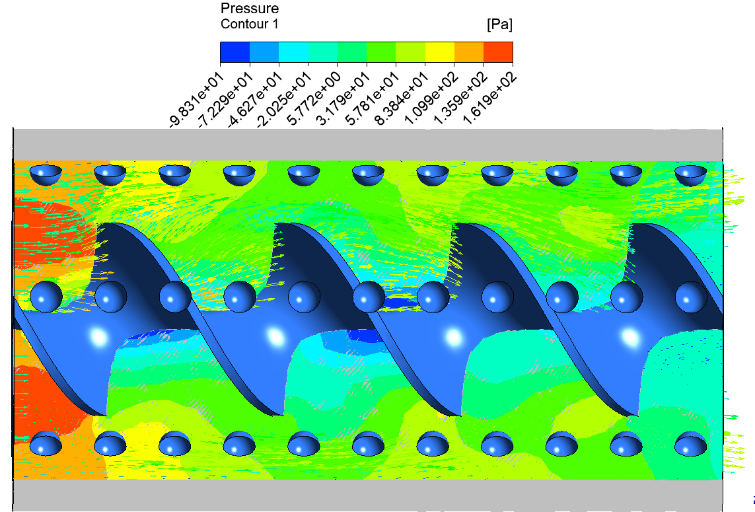
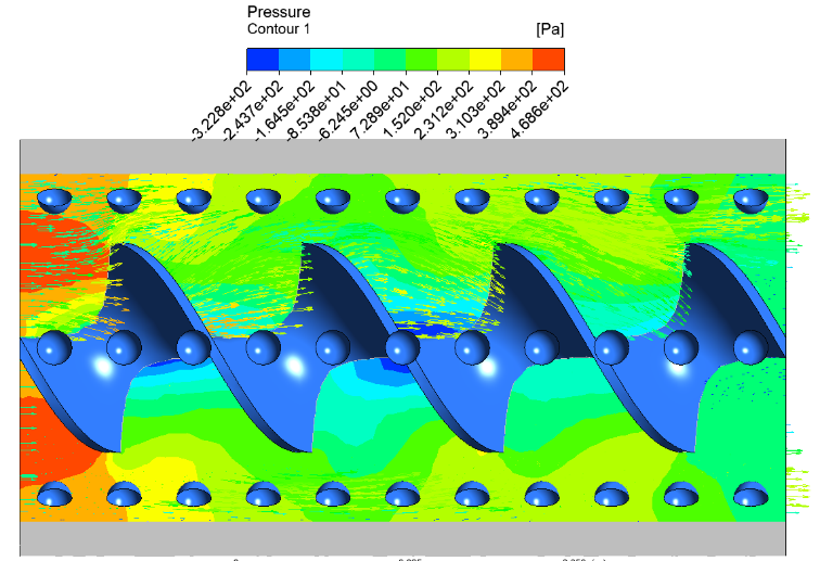
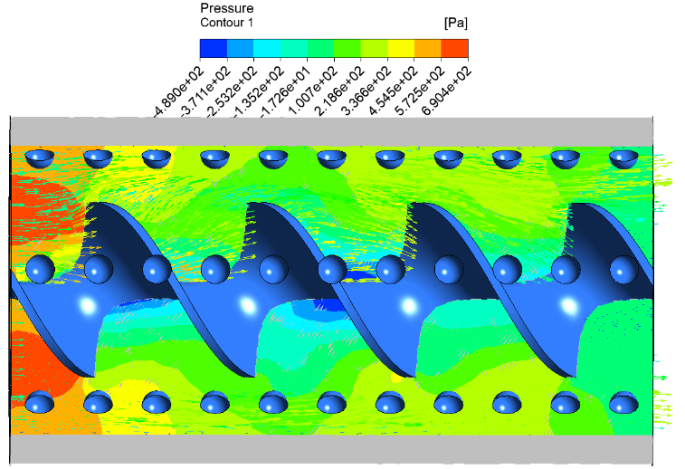
As Re increases to 15,000 and 20,000, the pressure drop becomes more pronounced due to the increase in inertial forces and turbulence intensity, as illustrated in Figure 12. The twisted tape causes a swirling motion which increases the frictional losses and the dimples cause flow separation and reattachment repeatedly. This causes large pressure fluctuations along the pipe wall. In the contour plots, the high-pressure region near the inlet remains dominant (red), but the pressure decays more rapidly along the axial direction, with a clear transition from red to yellow and then green over a shorter distance. The low-pressure zones (dark blue) inside the dimples become more distinct and larger in size, indicating stronger recirculation and vortex formation.
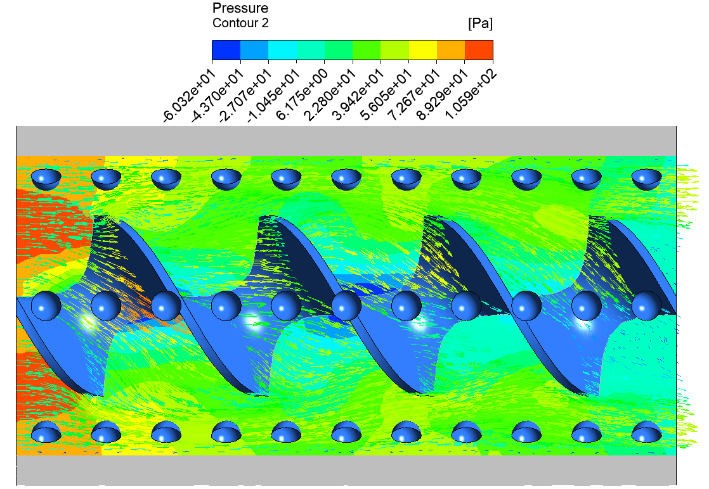
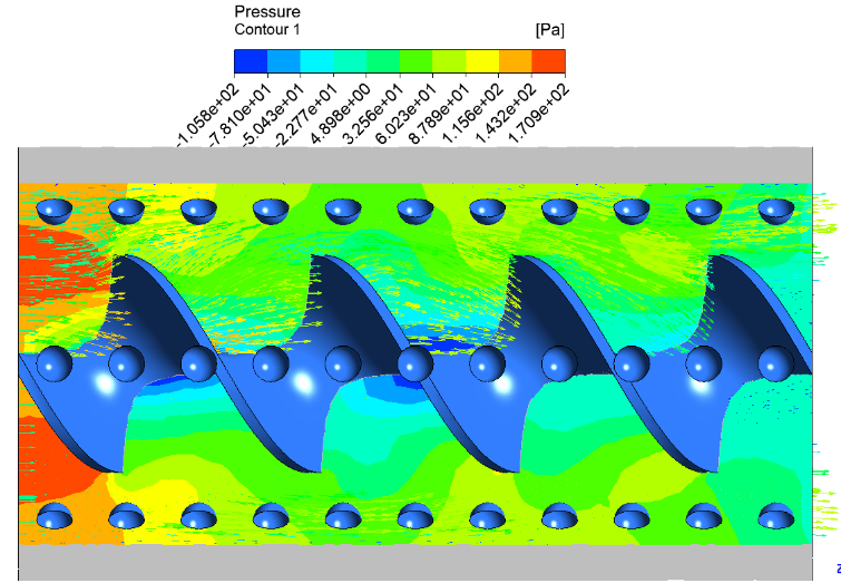
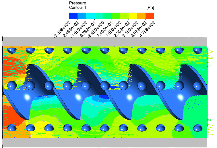
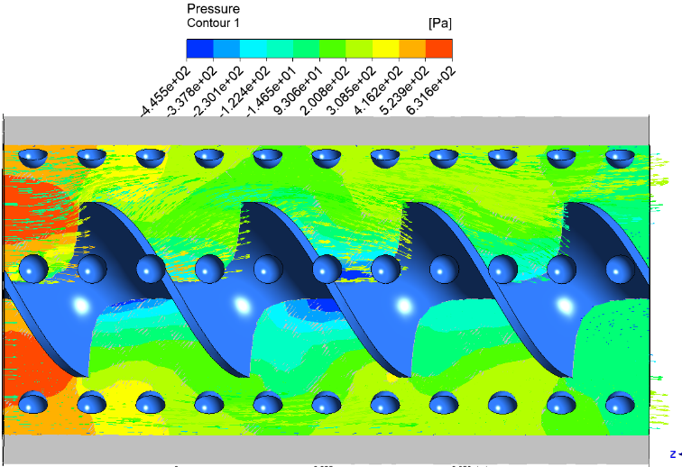
Figure 13 and Figure 14 show the behavior of pressure along pipe at higher (Re = 25,000 and 30,000), the pressure distribution becomes highly non-uniform due to intense turbulence and strong interaction between swirl flow and dimple-induced vortices. The overall pressure drops across the pipe significantly increases, reflecting higher frictional resistance. The contour colors show a steep gradient with an intense red color at the inlet and a fast transition to green and blue colors at the outlet. The flow around the dimples, especially near the wall, features continuous vortex shedding and reattachment, leading to alternating zones of high and low pressure. These are displayed as irregular patches of yellow, green and blue, representing dynamic pressure variations. The effect of hybrid nanofluids on pressure distribution is also demonstrated. The (Al2O3-CuO/water) hybrid nanofluid usually leads to the highest pressure drop due to its relatively higher viscosity and density which enhance the flow resistance and energy dissipation. This is seen in the contour plots as a faster transition to low pressure regions (green to blue) along the tube. The (Al2O3-TiO2/water) nanofluid has moderate pressure loss and a more uniform distribution of pressure contours. On the other hand, (Al₂O₃-ZnO/water) generally exhibits relatively lower pressure drop and higher-pressure levels over a longer axial distance as seen through the extended presence of yellow and light green colors in the contours.
The evolution of pressure contour along the twisted dimpled pipe clearly shows a transition from high pressure zones (red and orange) at the inlet to low pressure zones (green and blue) at the outlet. The higher Re the steeper the gradient is. This is because of the combined effects of the turbulence, swirl flow and the surface induced disturbances.
The formation of localized low-pressure regions within the dimples and their downstream areas plays a critical role in enhancing mixing but also contributes to increased pressure losses.
5.3 Temperature distribution analysis under varying Reynolds number and hybrid nanofluids
The temperature distribution within the twisted tape dimpled pipe is significantly influenced by the increase in (Re = 12,000 – 30,000) and the type of hybrid nanofluid employed, namely (Al₂O₃-ZnO/water), (Al₂O₃-TiO₂/water), and (Al₂O₃-CuO/water). The combined use of twisted tape inserts and surface dimples enhances mixing and disrupts the thermal boundary layer, which directly affects the temperature field and its contour evolution along the pipe.
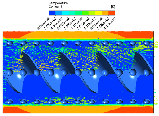
At the lower (Re ≈ 12,000), the flow exhibits relatively weaker turbulence, and heat transfer is mainly governed by conduction near the wall and limited convection in the core region, as illustrated in Figure 15. The contours of temperature show a gradual increase from the inlet to the outlet, which is due to the heat flux applied. The inlet region is typically cooler in color (blue to green) indicating lower fluid temperatures and the outlet region becomes warmer in color (yellow to light orange). Especially in the vicinity of the dimples a relatively thick thermal boundary layer is formed near the wall and some localized hot spots (orange regions) start to appear due to the reduced fluid motion and weak recirculation.
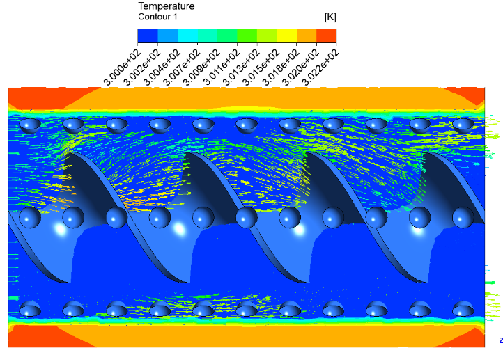
As Re increases to 15,000 and 20,000, the enhancement in turbulence intensity leads to improved convective heat transfer, as illustrated in Figure 16. The swirling flow generated by the twisted tape significantly intensifies radial mixing, transporting heat from the wall toward the core region more effectively. The dimples create localized vortices that continuously disrupt the thermal boundary layer. So, the temperature distribution becomes more uniform in the cross section. The transition of colors in the contour plots is livelier, with the high temperature regions close to the wall being less dominant. The hot regions (orange to red) become thinner and more dispersed, and the cooler regions (green to yellow) extend further toward the wall, indicating better heat removal.
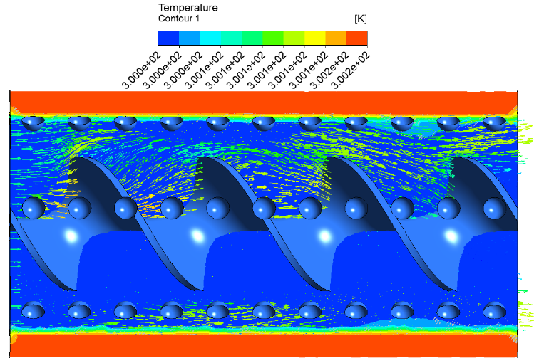
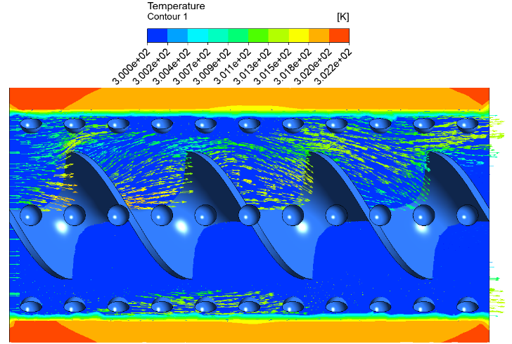
Figure 17 and Figure 18 show the behavior of temperature along pipe at higher (Re = 25,000 and 30,000), the flow becomes highly turbulent, and the combined effect of twisted tape and dimples produces strong mixing throughout the tube. This leads to a significant reduction in the thermal boundary layer thickness and a more homogeneous temperature field. The temperature contours clearly show a smoother gradient from inlet to outlet with a noticeable change in color distribution. Continuous heating results in the increase of the fluid temperature along the pipe but the maximum temperature values are lower than those for lower Re due to increased heat transfer rates. The contour colors are commonly blue/green at the inlet, yellow/orange at the outlet and less intense red areas. This means that thermal transport is efficient. In the vicinity of the dimples, small local color variations (green patches and yellow patches) show continuous mixing and reattachment of the flow.
The type of hybrid nanofluid also plays a crucial role in determining the temperature distribution. The hybrid nanofluid of (Al2O3-CuO/water) has better thermal conductivity, so it is more efficient in heat transfer and the total temperature levels in the pipe are lower. This is visible on the contours by a reduction of high temperature zones (less red/orange) and a more homogeneous distribution of moderate (green to yellow). The (Al₂O₃-TiO₂/water) nanofluid exhibits moderate enhancement with balanced temperature distribution, presenting significant enhancement over the base fluid. The hybrid nanofluid (Al2O3-ZnO/water), on the other hand tends to have relatively higher temperature regions near the wall indicating relatively lower thermal performance.
Afterwards, the evolution of the temperature contours clearly shows a transition from cooler colors (blue and green) at the inlet to warmer colors (yellow and orange) at the outlet, which reflects the heating process. With increasing Re, the cross-section temperature gradients become less steep due to an enhanced mixing and this results in a reduction of high temperature areas near the wall. Twisted tape inserts, dimpled surfaces and hybrid nanofluids are providing highly efficient heat transfer process because of the continuous disruption of the thermal boundary layer resulting in better energy transfer. This behavior demonstrates the effectiveness of the proposed configuration in achieving better thermal performance in heat exchanger applications.
5.4 Friction factor behavior under varying re and hybrid nanofluids
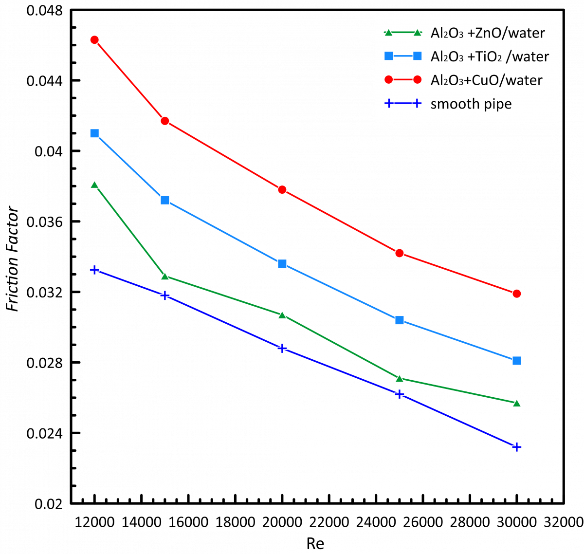
The friction factor behavior inside the twisted tape dimpled pipe is strongly influenced by the increase in (Re = 12,000 – 30,000) and the type of hybrid nanofluid used, namely (Al₂O₃-ZnO/water), (Al₂O₃-TiO₂/water), and (Al₂O₃- CuO/water), as presented in Figure 19. The presence of twisted tape inserts and surface dimples introduces additional flow resistance compared to a smooth tube, leading to higher friction losses; however, this increase is closely linked to the enhancement in turbulence and mixing within the flow.
Figure 19. Friction factor variation with Reynolds number (Re) for different hybrid nanofluids
At the lowest (Re ≈ 12,000), the friction factor shows relatively higher values than the higher Re because of the inverse relationship between friction factor and Re in turbulent flow. The flow has moderate swirl intensity from the twisted tape, and the dimples create localized disturbances. The friction factor shows a small variation along the pipeline length, with higher values in the near inlet, due to the flow development and the interaction with the twisted tape leading edge. Below each dimple, some minor fluctuations are observed; localized increases in shear stress are observed where there are flow separation and reattachment.
As the Re increases to 15,000 and 20,000, the friction factor decreases in its overall magnitude; however, the flow resistance remains significantly higher than that of a plain pipe due to intensified turbulence. The wall shear stress increases due to the intensified swirl flow and the interaction of the rotating flow with dimple-induced vortices. The fluid is repeatedly accelerated and decelerated along the pipe, which leads to a more oscillatory friction factor distribution. At Re = 15,000 and Re = 20,000 the friction factor is reduced by about 9–14% and 18–20%, respectively, compared to the value at Re = 12,000, but it is still high due to the combination of enhancement techniques.
At higher Re (Re = 25,000 and 30,000), the friction factor continues to decrease in trend with increasing Re; however, the absolute pressure losses remain significant because of the high flow velocity and strong turbulence intensity. The swirling motion induced by the twisted tape becomes highly energetic, and the dimples generate continuous vortex shedding, increasing energy dissipation near the wall. The friction factor distribution along the pipe shows relatively smoother behavior compared to lower Re, but localized peaks still exist at dimple locations. The reduction in friction factor reaches approximately 26–29% at Re = 25,000 and up to 31–33% at Re = 30,000 relative to the baseline case at Re = 12,000.
The type of hybrid nanofluid also has a significant effect on the behavior of the friction factor. The (Al2O3-CuO/water) hybrid nanofluid has the maximum value of the friction factor generally due to the higher values of the effective viscosity and density that increases the resistance to flow and the wall shear stress. This nanofluid may have an increment of about 13-16% in friction factor compared to (Al2O3-TiO2/water) and up to 21-25 % compared to (Al2O3-ZnO/water). (Al2O3-TiO2/water) nanofluid shows a moderate behavior. Generally, (Al2O3-ZnO/water) provides the lowest friction factor among the tested cases.
The behavior of the friction factor is greatly influenced by the nature of the hybrid nanofluid. The friction factor of the hybrid nanofluid (Al2O3-CuO/water) is generally maximum due to the higher values of effective viscosity and density that increase the resistance to flow and the wall shear stress. This nanofluid may have an increment of about 10-20% in the friction factor as compared to (Al2O3-TiO2/water) and up to 20-30% as compared to (Al2O3-ZnO/water). The nanofluid (Al2O3-TiO2/water) behaves in a moderate way. In the tested cases, the smallest friction factor is usually obtained by (Al2O3-ZnO/water).
Results show that the friction factor decreases with the increasing Re, but the overall pressure drop increases due to higher velocities. The use of hybrid nanofluids results in a small increase of the friction losses, especially for the higher viscosity mixtures such as (Al₂O₃-CuO/water). The simultaneous application of twisted tape and dimples results in a compromise between heat transfer enhancement and flow resistance. However, the observed percentage variations in friction factor with a significant enhancement in heat transfer performance confirm the effectiveness of the proposed configuration for advanced thermal applications.
5.5 Nusselt number behavior under varying Reynolds number and hybrid nanofluids
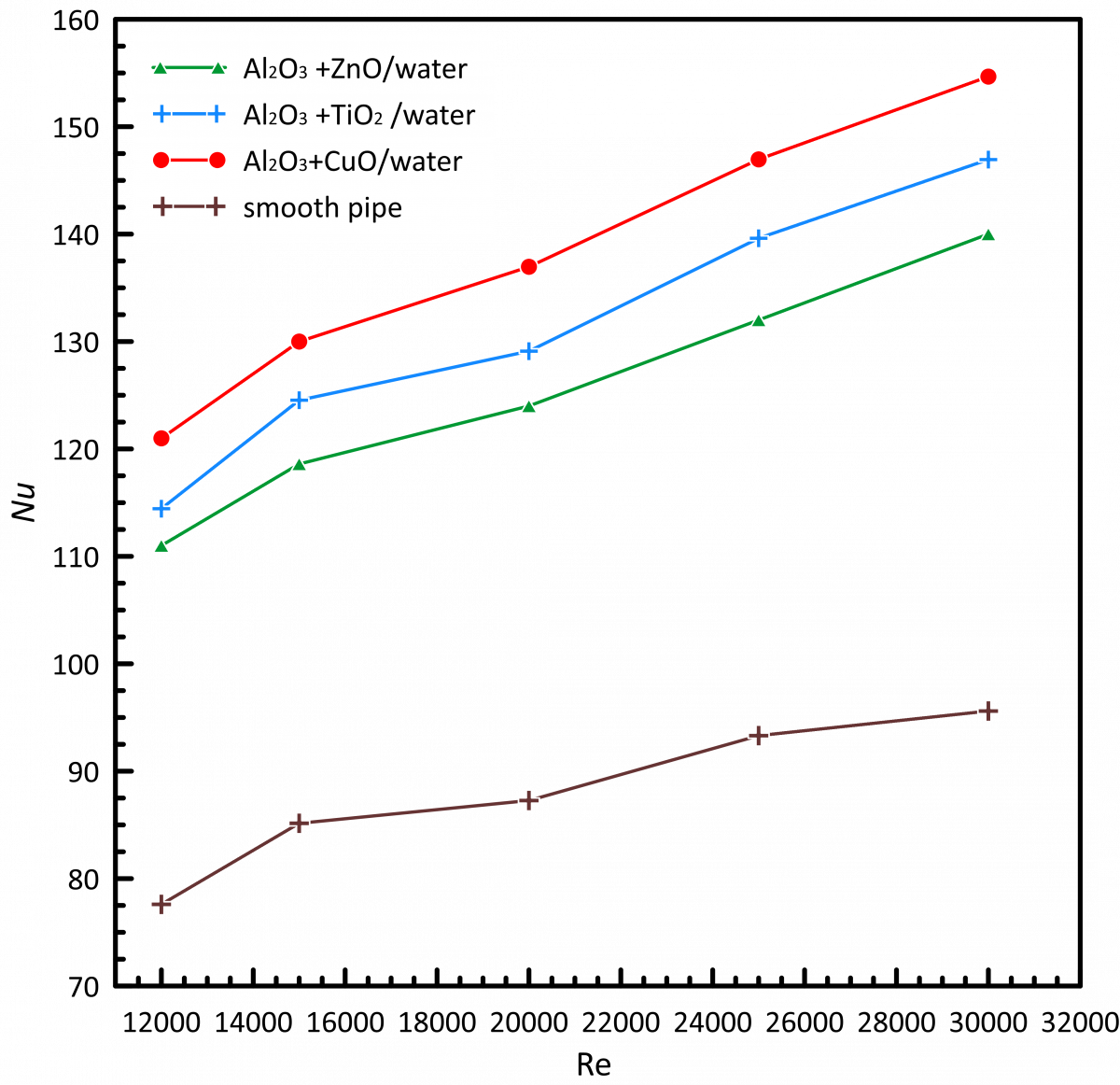
Figure 20 illustrates that the variation of the Nu along the twisted tape dimpled pipe is strongly dependent on the increase in (Re = 12,000–30,000) and the type of hybrid nanofluid used, namely (Al₂O₃-ZnO/water), (Al₂O₃-TiO₂/water), and (Al₂O₃-CuO/water), as illustrated in. The Nu, which represents the convective heat transfer enhancement relative to conduction, reflects the combined effects of turbulence intensity, thermal boundary layer disruption, and thermophysical properties of the working fluid.
Figure 20. Nusselt number (Nu) variation along twisted dimpled pipe for different hybrid nanofluids
At the lower (Re ≈ 12,000), the Nu shows moderate values along the pipe length. Near the inlet, relatively high local Nu are observed due to the initial thermal gradient and the flow developing region. However, the Nu decreases gradually as the fluid moves downstream, and it stabilizes when the thermal boundary layer becomes thicker. The presence of the twisted tape and dimples causes local enhancement, and as a result, small peaks are observed in the Nu distribution, especially downstream of each dimple where the flow reattachment occurs. It is observed that (Al2O3-CuO/water) nanofluid has the highest Nu among the hybrid nanofluids followed by (Al2O3-TiO2/water) and (Al2O3-ZnO/water) nanofluids due to the difference in the thermal conductivity.
At increasing Re of 15,000 and 20,000 the Nu increases remarkably along the whole tube. The increased swirl flow resulting from the twisted tape improves the mixing of fluid between the core and the near-wall regions, and the dimples break up the thermal boundary layer continuously. This results in increased convective heat transfer rates and more pronounced fluctuations of the local Nu. The Nu distribution along the tube shows periodic peaks at the dimple locations, which means the local heat transfer is strongly enhanced. The average Nu enhancement is approximately 7-9% at Re = 15,000 and 12-13% at Re = 20,000 (depending on the type of nanofluid) when compared to Re = 12,000.
At higher (Re = 25,000 and 30,000), the Nu reaches significantly higher values due to the highly turbulent flow regime. The combined effect of swirl motion and dimple-induced vortices results in continuous thinning and regeneration of the thermal boundary layer. The local Nu distribution becomes more uniform along the tube, although small oscillations persist due to repeated flow separation and reattachment. The enhancement becomes more substantial, with the average Nu increasing by approximately 19–22% at Re = 25,000 and up to 26–28% at Re = 30,000 compared to the baseline case at Re = 12,000. The (Al₂O₃ + CuO + water) hybrid nanofluid consistently achieves the highest enhancement, with an additional improvement of about 5–7% over (Al₂O₃-TiO₂/water) and 10–13% over (Al₂O₃-ZnO/water).
Nu distribution along the pipe length is generally higher near the inlet section due to the developing thermal boundary layer and then gradually decreases with the downstream distance, with periodic increases at the locations of dimples. The contour representation of Nu would show a change from moderate values near the inlet to higher values along the tube, especially at higher Re. Nu are higher in the regions near the dimples and the rotating core, which indicate better heat transfer, while the values are much lower in the small regions where the flow is temporarily steady.
The results clearly show that increasing the Re significantly increases the Nu and attributed to stronger turbulence and mixing. Further enhancement is achieved using hybrid nanofluids by improving the thermal properties of the fluid. The synergic effect of the twisted tape inserts and the dimpled surfaces provide the maximum heat transfer performance.
All these findings confirm that the presented configuration is highly effective for enhancing convective heat transfer, with substantial percentage increases in Nu across the investigated operating conditions, making it suitable for advanced thermal engineering applications.
5.6 Thermo-hydraulic performance analysis under varying Reynolds number and hybrid nanofluids
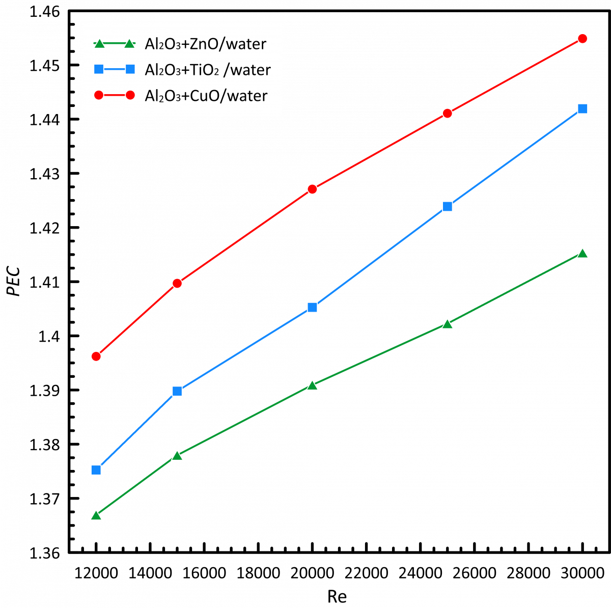
Figure 21 shows that the increase in (Re = 12,000 – 30,000) and the type of hybrid nanofluid used, which are (Al₂O₃-ZnO/water), (Al₂O₃-TiO₂/water) and (Al₂O₃-CuO/water), significantly affect the thermo-hydraulic performance of the twisted tape dimpled tube, which is usually evaluated using the Performance Evaluation Criterion (PEC). This parameter is the ratio of heat transfer enhancement Nu to the penalty in friction factor, thus giving a complete picture of the total system efficiency.
Figure 21. Thermo-hydraulic performance varies with different mixtures of hybrid nanofluids
At the lowest (Re ≈ 12,000), the thermo-hydraulic performance shows moderate improvement compared to a smooth pipe baseline. The enhancement in heat transfer due to the combined action of twisted tape-induced swirl flow and dimple-generated vortices is present but not fully developed. PEC values are slightly above unity, generally in the range of 1.37-1.46, indicating a beneficial but limited enhancement. Along the pipe length, higher performance near the inlet due to strong thermal gradients and developing flow conditions is observed. The performance then levels off downstream as the flow becomes more developed.
Thermo-hydraulic performance is remarkably improved with the Re increasing to 15,000 and 20,000. The increased turbulence improves the mixing between core and near-wall regions, which leads to a significant increase in the heat transfer rate that compensates for the increased friction losses. The PEC increases up to about 1.37–1.4 at Re = 15,000 and 1.39–1.42 at Re = 20,000. The distribution of performance becomes more uniform along the tube, with significant local enhancements occurring at the locations of the dimples due to the repeated disruption of the thermal boundary layer. The overall thermo-hydraulic performance is improved 2-3% at Re = 15,000 and 3-5% at Re = 20,000 than Re = 12,000.
At higher (Re = 25,000 and 30,000), the thermo-hydraulic performance reaches its maximum values within the investigated range. The strong interaction between the swirling flow induced by the twisted tape and the vortices generated by the dimples leads to highly efficient heat transfer. Although the friction factor penalty becomes more significant at these high flow rates, the gain in heat transfer dominates, resulting in PEC values ranging from approximately 1.4 to 1.46 at Re = 25,000 and up to 1.41–1.46 at Re = 30,000. This corresponds to an improvement of about 3–5% at Re = 25,000 and up to 4–6 % at Re = 30,000 compared to the baseline case at Re = 12,000.
The type of hybrid nanofluid has a great effect on the thermo-hydraulic performance. The highest PEC values are always observed in the (Al2O3-CuO/water) hybrid nanofluid due to the highest thermal conductivity, which remarkably enhances the heat transfer despite a moderate increase in the friction factor. It generally shows an additional enhancement of ~1–3% over (Al₂O₃-TiO₂/water) and 2–4% over (Al₂O₃-ZnO/water). The nanofluid (Al₂O₃-TiO₂/water) shows a good compromise. The (Al₂O₃-ZnO/ water) has the lowest PEC values because of its relatively lower enhancement in the thermal properties.
The thermo-hydraulic performance along the pipe length presents a characteristic trend, with higher values observed near the inlet due to developing flow and steep thermal gradients, followed by a relatively stable distribution with slight periodic increases at the dimple locations. These local peaks show the regions where the synergy between the swirl flow and the surface geometry makes the heat transfer to friction loss ratio maximum. The flow at the outlet is fully developed turbulent, and the performance is more uniform.
The results show that the thermo-hydraulic performance is significantly improved by increasing the Re due to better turbulence and mixing. This effect is also enhanced by the usage of hybrid nanofluids, especially for (Al2O3-CuO/water). There is a strong synergistic effect between twisted tape inserts and dimpled surfaces, leading to significant percentage improvements in performance. The results confirm that the proposed configuration is a very promising solution for achieving optimal thermal system efficiency and advanced heat exchanger applications.
5.7 Contribution of geometry and hybrid nanofluid to thermo-hydraulic enhancement
5.7.1 Comparative analysis of thermo-hydraulic performance
Table 9 presents a comparative assessment of the baseline smooth tube, the dimpled pipe fitted with a twisted tape insert using water, and the corresponding hybrid nanofluid cases. The results demonstrate that the geometric modifications constitute the primary source of heat-transfer enhancement. The dimples generate secondary vortical structures through repeated flow separation and reattachment, whereas the twisted tape induces a strong swirling motion that promotes radial mixing and increases fluid residence time within the heated section. Consequently, the thermal boundary layer is continuously disrupted, leading to higher Nu than those obtained in the smooth tube.
Table 9. Evaluation of the synergistic effects of dimples, twisted tape inserts, and hybrid nanofluid on thermos-hydraulic performance at Re = 30000
|
Cases |
Nu |
f |
PEC |
|
Smooth pipe +water |
95.6 |
0.0232 |
1 |
|
Dimpled pipe +Twisted Tape +water |
135 |
0.0250 |
1.38 |
|
Dimpled pipe + Twisted Tape + Al2O3-CuO/water |
154.66 |
0.0320 |
1.45 |
|
Dimpled pipe + Twisted Tape +Al2O3-TiO2/water |
146.9 |
0.0281 |
1.44 |
|
Dimpled pipe + Twisted Tape +Al2O3-ZnO/water |
140.0 |
0.0257 |
1.41 |
The introduction of hybrid nanofluids into the enhanced geometry provides an additional improvement in thermo-hydraulic performance. Owing to their superior effective thermal conductivity, hybrid nanofluids facilitate heat diffusion from the heated wall to the bulk fluid more efficiently than water. Although the presence of nanoparticles increases the effective viscosity and friction losses, the resulting heat-transfer enhancement remains dominant, leading to improved PEC values.
Among the investigated nanofluids, Al₂O₃–CuO/water consistently exhibits the highest thermo-hydraulic performance. This behavior is attributed to the relatively high thermal conductivity of CuO nanoparticles, which increases the effective thermal conductivity of the suspension and strengthens heat transport mechanisms within the flow field. As a result, the enhancement in heat transfer outweighs the associated increase in pressure losses, producing the highest PEC values among all investigated cases.
5.7.2 Flow and thermal field analysis
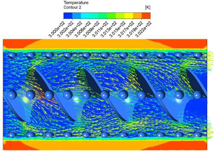
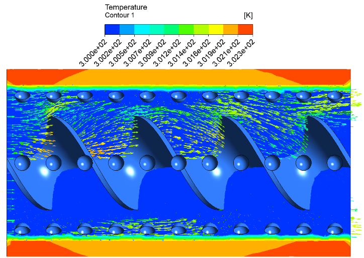
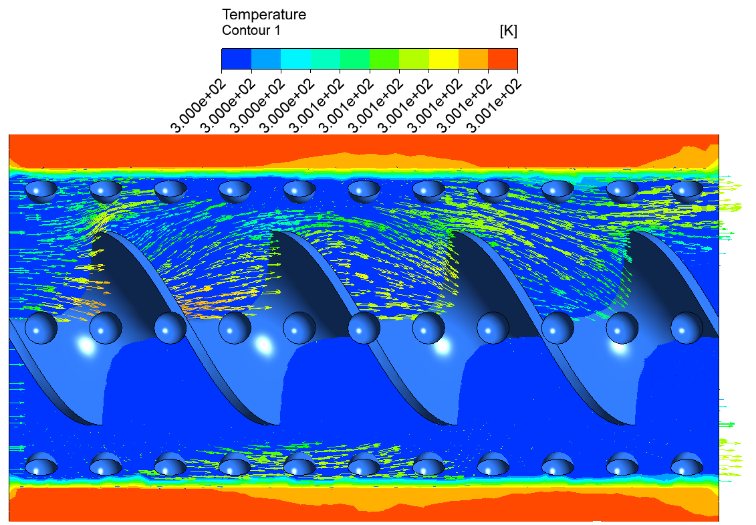
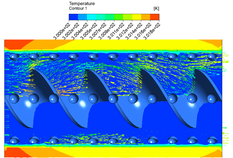
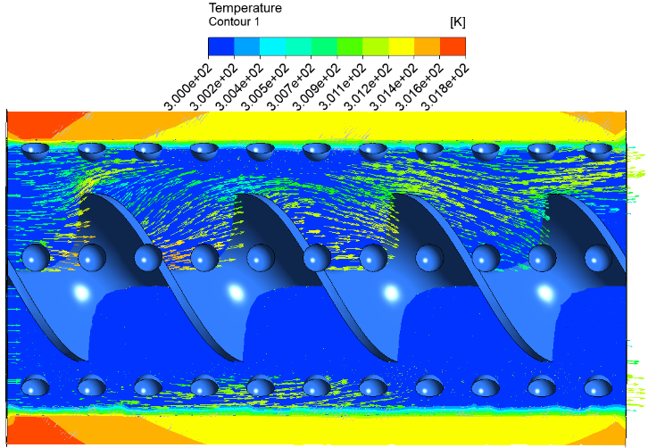
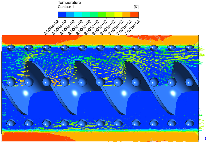
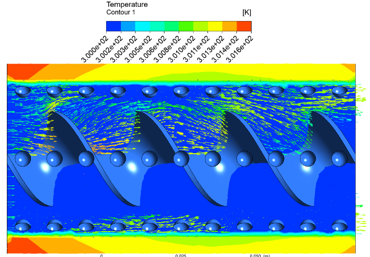
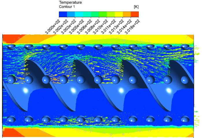
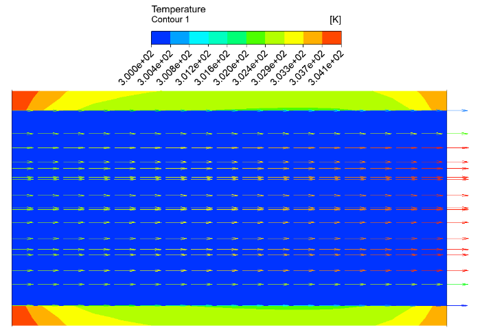
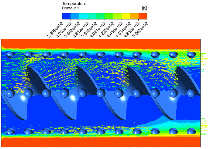
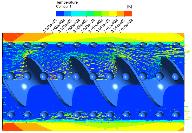
Figure 22 shows the temperature contours of the investigated hybrid nanofluids in the dimpled pipe fitted with a twisted tape insert. The contour plots provide further insight into the enhancement mechanisms responsible for the observed thermo-hydraulic behavior. The temperature contours indicate a progressive reduction in thermal boundary-layer thickness within the dimpled pipe fitted with twisted tape compared with the baseline configuration.
This behavior is attributed to the combined action of dimple-induced vortices and the swirl flow generated by the twisted tape, both of which intensify fluid mixing near the heated wall.
The evolution of pressure contour along the twisted dimpled pipe clearly shows a transition from high pressure zones (red and orange) at the inlet to low pressure zones (green and blue) at the outlet. The higher Re the steeper the gradient is. This is because of the combined effects of the turbulence, swirl flow and the surface induced disturbances.
The formation of localized low-pressure regions within the dimples and their downstream areas plays a critical role in enhancing mixing but also contributes to increased pressure losses.
These mechanisms continuously transport high-energy fluid from the pipe core toward the wall while simultaneously removing heated fluid from the near-wall region, thereby enhancing convective heat transfer. All the hybrid nanofluid cases exhibit a more homogeneous thermal field compared with water due to their improved effective thermal conductivity. The case of Al₂O₃–CuO/water nanofluid demonstrates the most uniform temperature distribution and the lowest thermal gradients near the wall. This behavior can be attributed to the relatively high thermal conductivity of CuO nanoparticles, which facilitates heat diffusion throughout the fluid domain. The combined effects of geometric modifications and enhanced thermophysical properties lead to superior heat-transfer performance, consistent with the observed increase in Nu and PEC values.
It can be observed that the temperature gradients near the heated wall decrease due to the enhanced mixing generated by the swirl flow and secondary vortices. The combined effect of the dimples and twisted tape continuously disrupts the thermal boundary layer, leading to improved heat transfer. The Al₂O₃–CuO/water hybrid nanofluid exhibits a more uniform temperature distribution compared with Al₂O₃–TiO₂/water and Al₂O₃–ZnO/water, owing to its superior effective thermal conductivity. All observations are consistent with the higher Nu and PEC values obtained for the Al₂O₃–CuO/water case.
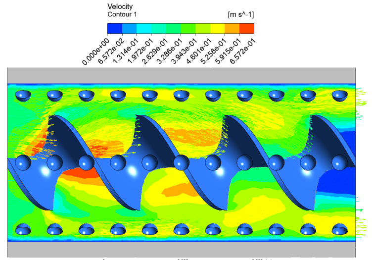
Figure 23 illustrates the velocity contours of the investigated hybrid nanofluids at Re = 30000. The velocity contours provide a clear visualization of the flow modification induced by the dimpled surface and twisted tape insert.
In the smooth tube, the velocity distribution remains relatively uniform, with limited radial motion and weak interaction between the core flow and the near-wall region.
However, the presence of dimples and twisted tape significantly alters the flow structure by generating swirl flow and secondary vortices throughout the pipe length. These flow structures increase fluid mixing and promote continuous momentum exchange between the core and wall regions.
Higher velocity gradients can be observed in the vicinity of the dimples and along the twisted tape surfaces, indicating local flow acceleration and enhanced turbulence intensity. Furthermore, repeated flow separation and reattachment occur around the dimples, producing recirculation zones that contribute to stronger mixing and improved transport of momentum and thermal energy. As the Re increases, the intensity of these vortical structures becomes more pronounced, leading to greater disruption of the hydrodynamic boundary layer and consequently higher heat-transfer rates.
The hybrid nanofluids exhibit flow patterns similar to those of water; however, the combined effect of enhanced fluid properties and intensified mixing results in superior thermo-hydraulic performance. Therefore, the velocity contours support the observed increases in Nu and PEC values and confirm the beneficial interaction between the geometric enhancement techniques and hybrid nanofluids.
A three-dimensional CFD investigation was performed to evaluate the thermo-hydraulic performance of a dimpled pipe fitted with a twisted tape insert using Al₂O₃–CuO/water, Al₂O₃–TiO₂/water, and Al₂O₃–ZnO/water hybrid nanofluids under turbulent flow conditions (Re = 12,000–30,000).
•The main finding of this study is that the synergistic effect of hybrid nanofluids, twisted tape inserts and dimpled pipe geometries provides substantial thermo-hydraulic enhancement compared to conventional enhancement methods over a Re range of 12,000-30,000.
•For all the cases studied, the Nu increased with Re due to the increased turbulence intensity, stronger secondary flow structures, and enhanced fluid mixing originating from the joint effect of the dimples and twisted tape insert.
•The friction factor decreased with increasing Re; however, it remained higher than that of a smooth pipe because of the additional flow resistance induced by the dimples and swirl flow generated by the twisted tape.
•The Al2O3-CuO/water showed the best heat-transfer performance and PEC values among the hybrid nanofluids investigated. This behavior is attributed to the superior effective thermal conductivity of the Al₂O₃–CuO/water suspension compared with the other investigated hybrid nanofluids.
•The comparative analysis showed that the geometric modifications are the main enhancement mechanism via vortex generation, swirl flow and thermal boundary-layer disruption, while the hybrid nanofluids provide enhancement through the improvement of the working fluid’s thermophysical properties.
•The simultaneous application of dimples, twisted tape inserts, and hybrid nanofluids produced the highest thermo-hydraulic performance, confirming a beneficial synergistic interaction between geometric enhancement and fluid-property enhancement techniques.
•The study configuration demonstrated promising thermo-hydraulic characteristics, the present investigation is limited to numerical simulations. Therefore, further experimental studies are recommended to assess nanoparticle stability, fouling behavior, long-term deposition effects, pumping-power requirements, and manufacturing feasibility before practical implementation.
|
B |
Dimensionless heat source length |
|
CP |
Specific heat, J·kg-1·K-1 |
|
Dh |
Hydraulic Diameter, m |
|
E |
Total energy per unit mass, J/kg |
|
f |
Darcy friction factor |
|
g |
Gravitational acceleration, m·s-2 |
|
h |
Heat transfer coefficient, W/m2·K |
|
k |
Turbulent kinetic energy, m2/s2 |
|
L |
Pipe length, m |
|
m |
Mass flow rate, Kg/s |
|
µ |
Dynamic viscosity, Pa·s |
|
µt |
Turbulent viscosity, Pa·s |
|
Nu |
Nusselt number |
|
p |
Pressure, Pa |
|
Prt |
Turbulent Prandtl number |
|
PEC |
Performance Evaluation Criterion |
|
∆p |
Pressure drop, Pa |
|
q |
Heat transfer rate, W |
|
Re |
Reynolds number |
|
u, v, w |
Velocity components in x,y,z directions, m/s |
|
ui |
Velocity vector component, m/s |
|
xi |
Cartesian coordinates, m |
|
T |
Temperature, K |
|
$\tau$ |
Stress tensor (effective), pa |
|
$\varepsilon$ |
Turbulent dissipation rate, m2/s2 |
|
$\lambda$ |
Thermal conductivity, W·m-1·K-1 |
|
ɸ |
Volume fraction nanoparticles |
|
ρ |
Fluid density, kg/m3 |
|
δij |
Kronecker delta |
|
Г |
Turbulence production term |
|
Subscripts |
|
|
bf |
Base fluid |
|
nf |
nanofluid |
|
hnf |
Hybrid nanofluid |
|
np1 |
Nanoparticle type 1 |
|
np2 |
Nanoparticle type 2 |
|
p |
Nanoparticle |
|
t |
Turbulent |
|
o |
Reference condition |
[1] Ajeel, R.K., Fayyadh, S.N., Ibrahim, A., Sultan, S.M., Najeh, T. (2024). Comprehensive analysis of heat transfer and pressure drop in square multiple impingement jets employing innovative hybrid nanofluids. Results in Engineering, 21: 101858. https://doi.org/10.1016/j.rineng.2024.101858
[2] Liu, W., Yang, K., Liu, Z.C., Ming, T.Z., Fan, A.W., Yang, C. (2010). Mechanism of heat transfer enhancement in the core flow of a tube and its numerical simulation. The Open Transport Phenomena Journal, 2: 9-15.
[3] Marzouk, S.A., Abou Al-Sood, M.M., El-Said, E.M.S., Younes, M.M., El-Fakharany, M.K. (2023). A comprehensive review of methods of heat transfer enhancement in shell and tube heat exchangers. Journal of Thermal Analysis and Calorimetry, 148: 7533-7564. https://doi.org/10.1007/s10973-023-12265-3
[4] Bdaiwi, M., Akroot, A., Abdul Wahhab, H.A., Hamoudi Assaf, Y., Nawaf, M.Y., Talal, W. (2023). Enhancement Heat exchanger performance by insert dimple surface ball inside tubes: A review. Results in Engineering, 19: 101323. https://doi.org/10.1016/j.rineng.2023.101323
[5] Sheikh, N.A., Ching, D.L.C., Khan, I. (2020). A comprehensive review on theoretical aspects of nanofluids: Exact solutions and analysis. Symmetry, 12(5): 725. https://doi.org/10.3390/sym12050725
[6] Tamna, S., Kaewkohkiat, Y., Skullong, S., Promvonge, P. (2016). Heat transfer enhancement in tubular heat exchanger with double V-ribbed twisted-tapes. Case Studies in Thermal Engineering, 7: 14-24. https://doi.org/10.1016/j.csite.2016.01.002
[7] Alesbe, I., Ibrahim, S.H., Aljabair, S. (2021). Mixed convection heat transfer in multi-Lid-driven trapezoidal annulus filled with hybrid nanofluid. Journal of Physics: Conference Series, 1973(1): 012065. https://doi.org/10.1088/1742-6596/1973/1/012065
[8] Mousavi Ajarostaghi, S.S., Zaboli, M., Javadi, H., Badenes, B., Urchueguia, J.F. (2022). A review of recent passive heat transfer enhancement methods. Energies, 15(3): 986. https://doi.org/10.3390/en15030986
[9] Ghachem, K., Aich, W., Kolsi, L. (2021). Computational analysis of hybrid nanofluid enhanced heat transfer in cross flow micro heat exchanger with rectangular wavy channels. Case Studies in Thermal Engineering, 24: 100822. https://doi.org/10.1016/j.csite.2020.100822
[10] Salam, B., Biswas, S., Saha, S., Bhuiya, M.M.K. (2013). Heat transfer enhancement in a tube using rectangular-cut twisted tape insert. Procedia Engineering, 56: 96-103. https://doi.org/10.1016/j.proeng.2013.03.094
[11] Alamgholilou, A., Esmaeilzadeh, E. (2012). Experimental investigation on hydrodynamics and heat transfer of fluid flow into channel for cooling of rectangular ribs by passive and EHD active enhancement methods. Experimental Thermal and Fluid Science, 38, 61-73. https://doi.org/10.1016/j.expthermflusci.2011.11.008
[12] Wijayanta, A.T., Pranowo, Mirmanto, Kristiawan, B., Aziz, M. (2019). Internal flow in an enhanced tube having square-cut twisted tape insert. Energies, 12(2): 306. https://doi.org/10.3390/en12020306
[13] Das, P.K., Santra, A.K., Ganguly, R., et al. (2024). An extensive review of preparation, stabilization, and application of single and hybrid nanofluids. Journal of Thermal Analysis and Calorimetry, 149(17): 9523-9557. https://doi.org/10.1007/s10973-024-13449-1
[14] Abdulhamed, A.J., Al-Akam, A., Khudhayer, W.J., Allw, A.S. (2024). Tubular heat enhancement using twisted tape inserts with large holes. Energy Engineering, 121(2): 273-290. https://doi.org/10.32604/ee.2023.045583
[15] Bhattad, A., Sarkar, J., Ghosh, P. (2020). Hydrothermal performance of different alumina hybrid nanofluid types in plate heat exchanger. Journal of Thermal Analysis and Calorimetry, 139(6): 3777-3787. https://doi.org/10.1007/s10973-019-08682-y
[16] Al-Obaidi, A.R., Alwatban, A. (2025). Improvement of thermohydraulic performance of flow based on novel dimpled tubes on response surface methodology and Taguchi technique-fitted experiment design. International Journal of Thermofluids, 25: 101038. https://doi.org/10.1016/j.ijft.2024.101038
[17] Liao, W.L., Jing, Z.B. (2024). Flow characteristics and heat transfer performance in tubes with dimples-protrusions. Case Studies in Thermal Engineering, 61: 104945. https://doi.org/10.1016/j.csite.2024.104945
[18] Alhamid, J., Al-Obaidi, A.R. (2021). Effect of concavity configuration parameters on hydrodynamic and thermal performance in 3D circular pipe using Al2O3 nanofluid based on CFD simulation. Journal of Physics: Conference Series, 1845(1): 012060. https://doi.org/10.1088/1742-6596/1845/1/012060
[19] Isaev, S., Leontiev, A., Chudnovsky, Y., Nikushchenko, D., Popov, I., Sudakov, A. (2019). Simulation of vortex heat transfer enhancement in the turbulent water flow in the narrow plane-parallel channel with an inclined oval-trench dimple of fixed depth and spot area. Energies, 12(7): 1296. https://doi.org/10.3390/en12071296
[20] Bellos, E., Tzivanidis, C. (2018). Enhancing the performance of evacuated and non-evacuated parabolic trough collectors using twisted tape inserts, perforated plate inserts and internally finned absorber. Energies, 11(5): 1129. https://doi.org/10.3390/en11051129
[21] Assaf, Y.H., Akroot, A., Alnamasi, K., Ismail, M.A. (2025). Investigation of heat transfer performance in heat exchangers using hybrid nanofluids and twisted tape inserts with fixed special rings. Scientific Reports, 15: 18450. https://doi.org/10.1038/s41598-025-02135-3
[22] Hamali, W., Almusawa, M.Y. (2022). Efficiency of nanoparticles on heat transfer of working fluid in presence of twisted tape. Case Studies in Thermal Engineering, 36: 102178. https://doi.org/10.1016/j.csite.2022.102178
[23] Aljabair, S., Mohammed, A.A., Alesbe, I. (2020). Natural convection heat transfer in corrugated annuli with H2O-Al2O3 nanofluid. Heliyon, 6(11): e05568. https://doi.org/10.1016/j.heliyon.2020.e05568
[24] Khafaji, H.Q.A., Wahhab, H.A.A., Alsaedi, S.S., Al-maliki, W.A.K., Alobaid, F., Epple, B. (2022). Thermal performance evaluation of a tubular heat exchanger fitted with combined basket–twisted tape inserts. Applied Sciences, 12(10): 4807. https://doi.org/10.3390/app12104807
[25] Ahmed, B.O., Ibrahim, A., Azeez, H.L., Dol, S.S., Al-Waeli, A.H.A., Jaber, M. (2024). Energy and exergy analysis of a newly designed photovoltaic thermal system featuring ribs, petal array, and coiled twisted tapes: Experimental analysis. Case Studies in Thermal Engineering, 63: 105388. https://doi.org/10.1016/j.csite.2024.105388
[26] Chu, W.X., Tsai, C.A., Lee, B.H., Cheng, K.Y., Wang, C.C. (2020). Experimental investigation on heat transfer enhancement with twisted tape having various V-cut configurations. Applied Thermal Engineering, 172: 115148. https://doi.org/10.1016/j.applthermaleng.2020.115148
[27] Ghazanfari, V., Shadman, M.M., Mansourzade, F., Amini, Y. (2024). Numerical investigation of thermal-hydraulic performance enhancement in helical coil heat exchangers with twisted tube geometries. Case Studies in Thermal Engineering, 60: 104744. https://doi.org/10.1016/j.csite.2024.104744
[28] Hamid, K.A., Azmi, W.H., Mamat, R., Sharma, K.V. (2019). Heat transfer performance of TiO2–SiO2 nanofluids in a tube with wire coil inserts. Applied Thermal Engineering, 152: 275-286. https://doi.org/10.1016/j.applthermaleng.2019.02.083
[29] Heeraman, J., Kumar, R., Chaurasiya, P.K., Beloev, H.I., Iliev, I.K. (2023). Experimental evaluation and thermal performance analysis of a twisted tape with dimple configuration in a heat exchanger. Case Studies in Thermal Engineering, 46: 103003. https://doi.org/10.1016/j.csite.2023.103003
[30] Hanafi, N.S.M., Ghopa, W.A.W., Zulkifli, R., Abdullah, S., Harun, Z., Abu Mansor, M.R. (2022). Numerical simulation on the effectiveness of hybrid nanofluid in jet impingement cooling application. Energy Reports, 8: 764-775. https://doi.org/10.1016/j.egyr.2022.07.096
[31] Wijayanta, A.T., Aziz, M., Kariya, K., Miyara, A. (2018). Numerical study of heat transfer enhancement of internal flow using double-sided delta-winglet tape insert. Energies, 11(11): 3170. https://doi.org/10.3390/en11113170
[32] Xu, Y., Islam, M.D., Kharoua, N. (2017). Numerical study of winglets vortex generator effects on thermal performance in a circular pipe. International Journal of Thermal Sciences, 112: 304-317. https://doi.org/10.1016/j.ijthermalsci.2016.10.015
[33] Wang, S., Wang, K., Lu, K., Zhang, Q. (2020). Experimental and numerical analysis for thermal-hydraulic characteristics in circular tubes with twisted tape and wire coil inserts. In E3S Web of Conferences, EDP Sciences, 165: 06051.
[34] Isaev, S., Nikushchenko, D., Sudakov, A., et al. (2022). Numerical Simulation of Heat Transfer Enhancement in the Paths of Propulsion Systems with Single-Row Spherical and Oval Dimples on the Wall. Energies, 15(19): 7198. https://doi.org/10.3390/en15197198
[35] Cengel, Y.A., Ghajar, A.J. (2015). Heat and Mass Transfer: Fundamentals and Applications (5th ed.). McGraw-Hill: New York, NY, USA.
[36] White, F.M. (2011). Fluid Mechanics (7th ed.). McGraw-Hill: New York, NY, USA. https://www.scirp.org/reference/referencespapers?referenceid=357707.
[37] Saha, S.K., Tiwari, M., Sundén, B., Wu, Z. (2016). Advances in Heat Transfer Enhancement. Springer Cham. https://doi.org/10.1007/978-3-319-29480-3