Mohammed A. Talal | Mohammed A. Mashrei*
© 2026 The authors. This article is published by IIETA and is licensed under the CC BY 4.0 license (http://creativecommons.org/licenses/by/4.0/).
OPEN ACCESS
Strengthening concrete beams with fiber-reinforced polymer (FRP) is an effective strengthening method. However, achieving a balance between strength and ductility remains challenging. This study evaluated carbon fiber-reinforced polymer (CFRP), basalt fiber-reinforced polymer (BFRP), and hybrid fiber-reinforced polymer (HFRP). Both externally bonded reinforcement (EBR) and externally bonded reinforcement on groove (EBROG) techniques were investigated. The influence of transverse grooves was also examined. Nine beams were tested, one of which was an unstrengthened beam. The results showed that EBROG outperformed EBR due to improved bonding. CFRP achieved an 84.5% increase in ultimate load with brittle failure behavior, while BFRP achieved a 71.7% increase with close deflection to the reference beam (RB) and a ductile failure mode. HFRP achieved the best balance between strength and ductility, with an 86.4% increase in ultimate load and a 19.75% decrease in deflection. The transverse grooves also contributed to enhancing the efficiency of EBROG, achieving a 131.6% increase in ultimate load when seven grooves were used with HFRP. In conclusion, HFRP with EBROG demonstrated outstanding structural performance in terms of resistance, stiffness and ductility while reducing the cost of strengthening, thus enhancing its practical applicability.
flexure, strengthening, basalt fiber-reinforced polymer, externally bonded reinforcement on groove, carbon fiber-reinforced polymer
Reinforced concrete (RC) structures may deteriorate due to several factors. These factors include poor construction practices, design errors, corrosion, chloride exposure, and excessive loading. Therefore, strengthening, repair, and rehabilitation techniques are often preferred. These methods reduce the need for complete reconstruction. The use of fiber-reinforced polymer (FRP) composites in strengthening structural elements has proven to be highly effective due to their clear advantages and structural benefits [1]. Carbon fiber-reinforced polymer (CFRP) composites are among the most widely used materials for strengthening and are characterized by high tensile strength, low weight, high corrosion resistance, and low thermal conductivity compared to steel [2]. Strengthening with this material improves elements' resistance to bending and shear, extending their lifespans, and allows for various methods of bonding them to structural elements such as beams, columns, and slabs [3]. Numerous proposals have been made for bonding FRP materials in their various forms to structural elements. Some research has employed the near-surface mounting (NSM) technique, which involves creating a groove into which a bar is inserted and applying an adhesive for fixation [4-6]. Other studies have focused on the externally bonded reinforcement (EBR) technique, which involves bonding FRP sheets to the tension or shear surface. This is one of the most widespread strengthening techniques used to improve the flexural strength of concrete beams [7-11]. This technique is easy to implement and widely used. It also provides acceptable strengthening performance. However, premature debonding remains its major drawback. This occurs because the strengthening fails before achieving the full mechanical properties of the FRP due to poor bonding with the concrete surface [12-15].
Studies then focused on developing the EBR technique to address its shortcomings. Mostofinejad et al. [16] developed the externally bonded strengthening on grooves (EBROG) technique. In this method, longitudinal grooves are created on the concrete surface and filled with a suitable epoxy. FRP is then applied and bonded to the concrete surface to increase the bond area. Several studies evaluating and understanding flexural behavior indicated that the use of the EBROG technique can negate, or at least delay, the onset of debonding [16].
The effects of groove shape (triangular, curved, rectangular), number of layers, and groove orientation have previously been studied. It was found that a rectangular groove shape, two FRP layers, and the use of both longitudinal and transverse grooves yielded the best results [17]. Other studies evaluating the failure mode found that the failure mode shifted from debonding at the EBR to rupture of the fiber or concrete cover separation in EBROG [18, 19]. Various other variables were examined, including the effects of groove dimensions (length, width, depth) [20], the use of inclined grooves [21], the addition of U-wrap anchorage [22], the effects of concrete strength on the technique [23], and the effects of the strengthening material type (sheet, laminate) and number of grooves [19]. There is a second form of this technique, externally bonded reinforcement in grooves (EBRIG), which is remarkably similar to the EBROG technique, with the exception that FRP panels are inserted into the grooves. This technique is somewhat more difficult to implement [17]. All previous studies have shown that the EBROG technique is a good development and, in all cases, gives better results than the EBR technique. Despite its advantages, CFRP exhibits brittle behavior. Its ultimate tensile strain is approximately 1.7% [24]. CFRP-strengthened elements may fail suddenly after reaching their ultimate capacity. Consequently, the structural ductility is reduced [25]. The strengthened beams showed less ductile behavior than the control beam, despite the increased load capacity of the samples [26-28]. A higher safety factor or a limit on the ultimate load capacity was proposed to prevent sudden collapse upon reaching the ultimate possible load [29]. This necessitated development to improve the structural strengthening performance to meet higher safety levels. Therefore, studies emerged on the use of hybrid composites combining carbon fibers with aramid fiber reinforcement polymer (AFRP), glass fiber reinforcement polymer (GFRP), and basalt fiber-reinforced polymer (BFRP) to overcome such issues [30-32].
Hybrid composites have not been investigated sufficiently. Therefore, further studies are needed to better understand and develop this concept. One study investigated the use of carbon and basalt composites as a hybrid strengthening system using only the EBR technique. The results indicated an increase in strength and deformability, but debonding failure was prevalent in the specimens due to the use of the EBR [33].
Although BFRP provides higher deformability and lower cost than CFRP, its application within hybrid strengthening systems remains insufficiently investigated, which includes good ductility, with an ultimate tensile strain of 3.2% [34], and high fire resistance, as it retains 90% of its strength below 600 ℃, compared to carbon and glass, which lose strength at this temperature. Basalt fibers are extracted from basalt rocks after the melting process, cut into small pieces, and then converted into fibers without the addition of any other materials, which reduces production costs. It also has higher alkali resistance than carbon [29]. Table 1 shows a summary of previous studies. Previous studies have demonstrated the effectiveness of FRP materials for strengthening RC elements. These materials significantly improve structural performance and load-carrying capacity. They have also confirmed that CFRP is characterized by high tensile strength, light weight, and excellent corrosion resistance. However, its most prominent drawbacks are brittle behavior and low ductility. In contrast, studies have shown that BFRP possesses higher ductility, good fire resistance, and relatively lower cost. Furthermore, studies agree that EBR is one of the most widely used strengthening techniques due to its ease of implementation, but it suffers from premature debonding. EBROG, on the other hand, has proven superior in improving the bond between FRP and concrete and reducing or even eliminating premature debonding failure compared to EBR.
Table 1. Summary of previous studies
|
Literature |
Variables |
Outcomes |
||||
|
Type of Technology |
Type of Material |
No. of Layers |
Type of Grooves |
No. of Grooves |
||
|
El Gamal et al. [6] |
EBR |
CFRP |
1 |
---- |
---- |
Increase in loading capacity by 32.6% with debonding failure |
|
EBR |
CFRP |
2 |
---- |
---- |
Increase in loading capacity by 56.1% with debonding failure |
|
|
Hawileh et al. [9] |
EBR |
CFRP |
1 |
---- |
---- |
Increase in loading capacity by 57.3%, and decrease in ductility by 38.0% with debonding failure |
|
EBR |
GFRP |
1 |
---- |
---- |
Increase in loading capacity by 30.7%, and decrease in ductility by 20.0% with debonding failure |
|
|
EBR |
GFRP + CFRP |
2 |
---- |
---- |
Increase in loading capacity by 83.0%, and decrease in ductility by 42.0% with debonding failure |
|
|
EBR |
GFRP + CFRP + GFRP |
3 |
---- |
---- |
Increase in loading capacity by 98.0% and decrease in ductility by 54.0% with debonding failure |
|
|
Mostofinejad and Mahmoudabadi [16] |
EBROG |
CFRP |
1 |
Transverse, length 80 mm, width 3 mm, depth 2 mm |
9 |
Increase in bond strength by 8.0% |
|
EBROG |
CFRP |
1 |
Diagonal, length 80 mm, width 3 mm, depth 2 mm |
12 |
Increase in bond strength by 10.0% |
|
|
EBROG |
CFRP |
1 |
Longitudinal, length 370 mm, width 3 mm, depth 2 mm |
5 |
Increase in bond strength by 24.0% |
|
|
EBROG |
CFRP |
1 |
Longitudinal, length 370 mm, width 3 mm, depth 10 mm |
5 |
Increase in bond strength by 37.0% |
|
|
Mashrei et al. [17] |
EBR |
CFRP |
1 |
---- |
---- |
Increase in loading capacity by 16.2% with debonding failure |
|
EBROG |
CFRP |
1 |
Longitudinal, triangular shape |
3 |
Increase in loading capacity by 35.5% with cover separation failure |
|
|
EBROG |
CFRP |
1 |
Longitudinal, rectangular shape |
3 |
Increase in loading capacity by 62.0% with cover separation failure |
|
|
EBROG |
CFRP |
1 |
Longitudinal, curved shape |
3 |
Increase in loading capacity by 42.0% with cover separation failure |
|
|
EBROG |
CFRP |
1 |
Transverse, rectangular shape |
8 |
Increase in loading capacity by 42.0% with cover separation failure |
|
|
EBROG |
CFRP |
2 |
Transverse, rectangular shape |
8 |
Increase in loading capacity by 103% with cover separation failure |
|
|
Mostofinejad et al. [18] |
EBR |
CFRP |
1 |
---- |
---- |
Increase in loading capacity by 51.1% with debonding failure |
|
EBR |
CFRP |
2 |
---- |
---- |
Increase in loading capacity by 62.6% with debonding failure |
|
|
EBROG |
CFRP |
1 |
Longitudinal |
3 |
Increase in loading capacity by 52.7% with rupture CFRP failure |
|
|
EBROG |
CFRP |
2 |
Longitudinal |
3 |
Increase in loading capacity by 101.4% with cover separation failure |
|
|
Abed et al. [19] |
EBROG |
CFRP (sheet) |
1 |
Longitudinal |
3 |
Increase in loading capacity by 65.4% with cover separation failure |
|
EBROG |
CFRP (laminate) |
1 |
Longitudinal |
3 |
Increase in loading capacity by 32.0% with cover separation failure |
|
|
Han et al. [20] |
EBROG |
CFRP |
1 |
Longitudinal, length 200 mm, width 5 mm, depth 5 mm |
3 |
Increase in bond strength by 21.0% |
|
EBROG |
CFRP |
1 |
Longitudinal, length 200 mm, width 10 mm, depth 10 mm |
3 |
Increase in bond strength by 32.0% |
|
|
EBROG |
CFRP |
1 |
Longitudinal, length 200 mm, width 15 mm, depth 15 mm |
3 |
Increase in bond strength by 47.0% |
|
|
EBROG |
CFRP |
1 |
Longitudinal, length 200 mm, width 20 mm, depth 20 mm |
3 |
Increase in bond strength by 61.0% |
|
|
Mostofinejad et al. [28] |
EBR |
CFRP |
3 |
---- |
---- |
Increase in loading capacity by 87.0%, and decrease in area under curve by 64.0% with debonding failure |
|
EBROG |
CFRP |
3 |
Longitudinal |
3 |
Increase in loading capacity by 122.0%, and decrease in area under curve by 14.0% with debonding and cover separation failure |
|
|
EBRIG |
CFRP |
3 |
Longitudinal |
3 |
Increase in loading capacity by 132.0% and decrease in area under curve by 3.0% with cover separation failure |
|
|
Choobbor et al. [33] |
EBR |
CFRP |
2 |
---- |
---- |
Increase in loading capacity by 72.0%, and ductility is 1.75 with cover separation failure |
|
EBR |
BFRP |
2 |
---- |
---- |
Increase in loading capacity by 62.0%, and ductility is 3.64 with rupture BFRP failure |
|
|
EBR |
CFRP + BFRP |
2 |
---- |
---- |
Increase in loading capacity by 66.0%, and ductility is 2.02 with flexural failure |
|
Despite this, the efficiency of hybrid systems and a comprehensive understanding of their structural behavior remain insufficiently studied, particularly regarding the possibility of combining the high strength offered by CFRP with the superior ductility of BFRP within a single strengthening system. Furthermore, the use of the CFRP–BFRP hybrid system with the EBROG technique has not been studied, according to a review of previous studies, representing a key research gap in this study.
This study addresses the existing research gap by investigating the structural performance of CFRP–BFRP hybrid strengthening systems combined with EBROG technology. Particular attention is given to the effects of material type, strengthening technique, and transverse grooves on load capacity, stiffness, ductility, and failure mode.
Nine RC beams were cast and tested under four-point loading. The study evaluated the effects of hybrid FRP composites (CFRP and BFRP) and the EBR and EBROG techniques on flexural behavior. Two EBR beams and six EBROG beams were tested, the results from which were compared to a reference beam (RB) that was fabricated without strengthening. Several variables were investigated. These variables included CFRP strengthening, BFRP strengthening, and hybrid strengthening. The effects of longitudinal grooves and transverse grooves were also examined. The material properties, beam specimen details, experimental equipment, and testing procedures are presented in detail below.
2.1 Material properties
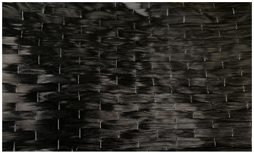
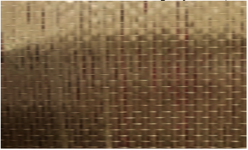
The materials used in this study include CFRP and BFRP sheets, cement, fine and coarse aggregates, steel reinforcing bars, and epoxy adhesive. The cement met the requirements of ASTM-C150 [35]. The coarse and fine aggregates met the requirements of ASTM-C33 [36]. The 8 mm diameter steel bars used for longitudinal and stirrup reinforcement, whose properties are reported in Table 2, were tested according to BS 4449-2009. Table 2 also shows the properties of the adhesive (epoxy-Sikadur C330) [37] and the FRP sheets (according to the manufacturer) [34, 38]. Figure 1 shows the unidirectional carbon fiber and basalt used for strengthening.
(a) Carbon fiber-reinforced polymer (CFRP)
(b) Basalt fiber-reinforced polymer (BFRP)
Figure 1. Unidirectional carbon fibers and basalt
Table 2. Material properties
|
Materials |
Property |
Value |
|
Steel bar |
Bar Diameter (mm) |
8 |
|
Yield Strength (MPa) |
478 |
|
|
Ultimate Tensile Strength (MPa) |
606 |
|
|
Elongation (%) |
15 |
|
|
CFRP sheet |
Ultimate Tensile Strength (MPa) |
4000 |
|
Tensile Elastic Modulus (GPa) |
230 |
|
|
Ultimate Tensile Strain (%) |
1.7 |
|
|
Mass per area (g/m²) |
304 |
|
|
Thickness (mm) |
0.167 |
|
|
BFRP sheet |
Ultimate Tensile Strength (MPa) |
2800 |
|
Tensile Elastic Modulus (GPa) |
85 |
|
|
Ultimate Tensile Strain (%) |
3.2 |
|
|
Mass per area (g/m²) |
300 |
|
|
Thickness (mm) |
0.15 |
|
|
Epoxy resin |
Tensile Strength (MPa) |
33.8 |
|
Flexural Strength (MPa) |
60.6 |
|
|
Flexural Modulus (GPa) |
3.489 |
|
|
Compressive strength (MPa) |
80 |
|
|
Elongation (%) |
1.2 |
|
|
Mixing ratio (A:B) |
4:1 |
|
|
Cure time (tack-free time) (hours) |
4-5 |
|
|
Minimum application temperature (℃) |
4 |
|
|
Maximum application temperature (℃) |
35 |
2.2 Mixing, casting, and curing
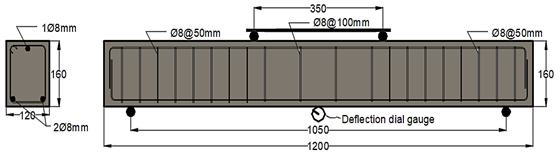
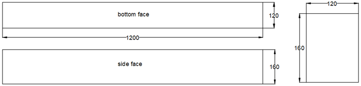
A tested concrete mix with a compressive strength, f'c, of 45 MPa, as per the proportions reported in Table 3, was used to cast the beams. The beam dimensions were 1200 × 160 × 120 mm. Each beam was longitudinally reinforced with two 8 mm diameter steel bars at the tension face and one bar at the compression face to secure the stirrups. To resist and prevent shear failure in all cases, 8 mm diameter stirrups were used with a spacing of 50 mm between them in the shear zones, and 100 mm in the bending zone center-to-center.
Table 3. Concrete mix (kg/m3)
|
Cement |
Fine Aggregate |
Coarse Aggregate |
Water |
Plasticizer |
|
410 |
738 |
1033 |
148 |
2.5 |
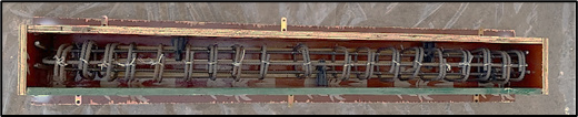
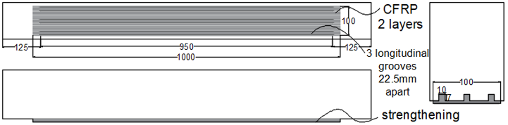
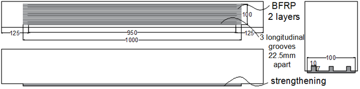
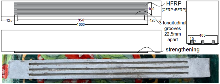
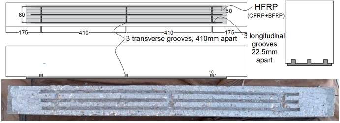
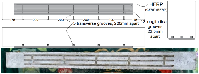
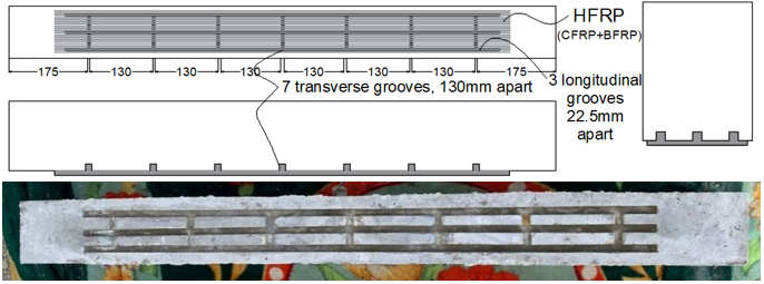
Figure 2 illustrates the details of the beam reinforcement. Wooden inserts were fixed to the formwork at the required locations to create grooves with a 7 mm deep and 10 mm wide cross-section, with a length of 950 mm for the longitudinal grooves and 80 mm for the transverse grooves. The forms were cast after thorough mixing of the materials. Figure 3 illustrates details of groove formation and casting. The molds were removed 24 hours after casting and cured for 28 days by covering them with a damp cloth and plastic sheeting to prevent moisture loss. The strengthening procedure was then performed.
Figure 2. Beam reinforcement details (all dimensions in mm)
(a) Groove formation
(b) Fixing the reinforcement
(c) Concrete filling and vibration
Figure 3. Details of groove formation and casting
2.3 Details of beam specimens
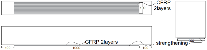
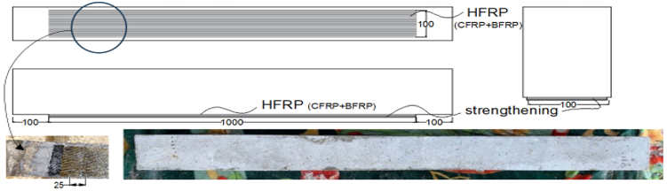
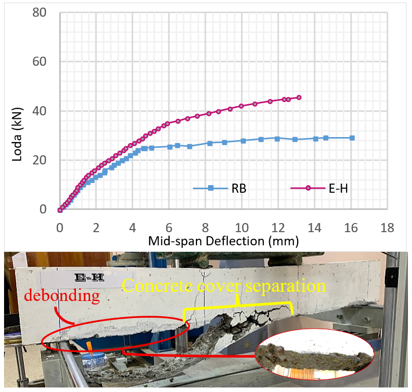
Nine specimens were fabricated, consisting of the RB and two beams strengthened via EBR technique. The first beam, designated E-2C, used two layers of CFRP, while the second, designated E-H, used HFRP. Three beams were strengthened using EBROG technique with three adjacent longitudinal grooves on the underside (tensile face). Each groove was 950 mm long, but the first beam had two layers of CFRP, the second two layers of BFRP, and the third two layers of HFRP, designated G-2C3L, G-2B3L, and GH3L, respectively. The last three beams were strengthened using EBROG with HFRP, employing three longitudinal grooves after being enhanced with transverse grooves: three for the first beam, five for the second, and seven for the third. These specimens were designated G-H3L3T, G-H3L5T, and G-H3L7T, respectively. The cross-section of the grooves was 10 mm wide and 7 mm deep. Figure 4 shows details of the specimens, while Table 4 summarizes these details.
(a) Reference beam (RB)
(b) Externally bounded reinforcement-two layers of CFRP (E-2C)
(c) Externally bounded reinforcement – HFRP layers (E-H)
(d) Externally bounded reinforcement on groove – two layers of CFRP, three longitudinal grooves (G-2C3L)
(e) Externally bounded reinforcement on groove – two layers of BFRP, three longitudinal grooves (G-2B3L)
(f) Externally bounded reinforcement on groove – HFRP layers, three longitudinal grooves (G-H3L)
(g) Externally bounded reinforcement on groove – HFRP layers, three longitudinal and three transverse grooves (G-H3L3T)
(h) Externally bounded reinforcement on groove – HFRP layers, three longitudinal and five transverse grooves (G-H3L5T)
(i) Externally bounded reinforcement on groove – HFRP layers, three longitudinal and seven transverse grooves (G-H3L7T)
(j) Two-layer CFRP, BFRP and HFRP at the tension face
Table 4. Details of beam specimens
|
Specimen Designation |
No. of Longitudinal Grooves |
No. of Transverse Grooves |
No. of CFRP Layers |
No. of BFRP Layers |
Variables Material, Groove Layout, Interface Condition |
|
RB |
--- |
--- |
--- |
--- |
Without strengthening |
|
E-2C |
--- |
--- |
2 |
--- |
2-layer CFRP, without grooves; the surface is roughened by grinding. |
|
E-H |
--- |
--- |
1 |
1 |
HFRP (1-layer CFRP + 1-layer BFRP), without grooves, the surface is roughened by grinding. |
|
G-2C3L |
3 |
--- |
2 |
--- |
2-layer CFRP, 3 longitudinal grooves, the surface is roughened by grinding. |
|
G-2B3L |
3 |
--- |
--- |
2 |
2-layer BFRP, 3 longitudinal grooves, the surface is roughened by grinding. |
|
G-H3L |
3 |
--- |
1 |
1 |
HFRP, 3 longitudinal grooves, the surface is roughened by grinding. |
|
G-H3L3T |
3 |
3 |
1 |
1 |
HFRP, 3 longitudinal and 3 transverse grooves, the surface is roughened by grinding. |
|
G-H3L5T |
3 |
5 |
1 |
1 |
HFRP, 3 longitudinal and 5 transverse grooves, the surface is roughened by grinding. |
|
G-H3L7T |
3 |
7 |
1 |
1 |
HFRP, 3 longitudinal and 7 transverse grooves, the surface is roughened by grinding. |
2.4 Strengthening procedures
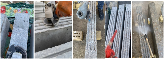
Twenty-eight days subsequent to the casting date, the beams were strengthened by preparing the underside of the beam using a grinding machine and a suitable disc to remove the weak surface layer; this included the entire surface area of the grooves. The surface was then thoroughly cleaned using compressed air and water, followed by drying with compressed air. It was then left to dry completely, and its cleanliness was maintained until the strengthening was applied.
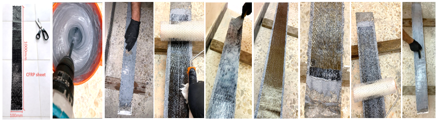
Figure 5 shows the preparation, cleaning, and washing process. The strengthening bonding process, according to the EBR strengthening technique, involved the application of a layer of adhesive epoxy using a scraper blade. A layer of FRP sheet (1000 mm long, 100 mm wide) was then applied after being saturated with epoxy. This was then pressed using a special roller to remove bubbles. Another layer of epoxy was applied, followed by a second layer of epoxy-saturated FRP sheet, shorter than the first layer, in accordance with ACI PRC 440.2-2023.
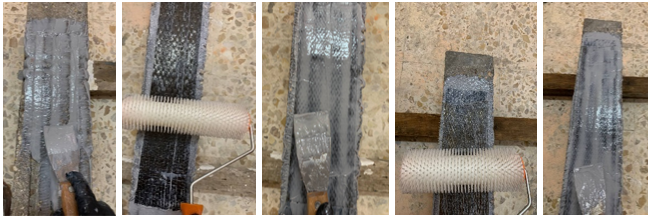
Figure 6 shows the EBR strengthening process. The EBROG technique is similar, with the main difference being that the grooves are first filled with epoxy, then the entire surface is covered, and the strengthening layers are adhered to it, as described in the EBR technique. It should be noted that a CFRP layer was applied first, followed by a BFRP layer, in the HFRP hybrid system. All strengthened samples were cured for seven days according to the manufacturing instructions. Figure 7 shows the EBROG strengthening process.
Figure 5. Preparation, roughing, cleaning, and washing process
Figure 6. Externally bonded reinforcement (EBR) strengthening process
Figure 7. Externally bonded reinforcement on groove (EBROG) strengthening process
2.5 Test method for the loading machine
A four-point loading system with a load capacity of 200 kN was used. The beam was placed on simple circular supports with a diameter of 25 mm and a clear span of 1050 mm between the supports. A load of 0.25 kN/s was applied through two circular loading points with a diameter of 25 mm at the midpoint of the beam, spaced 350 mm apart. The load capacity was measured using a monitor, and the deflection was measured using a digital dial gauge (0.1 mm accuracy) at the midpoint of the lower span of the beam. Crack propagation was carefully monitored visually and with a camera, as shown in Figure 8.
Figure 8. Four-point load testing
This section presents the results of the load-deflection curve, cracking load (Pcr), ultimate load (Pu), deflection (∆u), the percentage increase or decrease relative to RB (e.g., (Pcr − Pcr, RB) / Pcr, RB), failure mode for each beam, ductility, stiffness, and study variables.
3.1 Load-deflection curves and failure mode
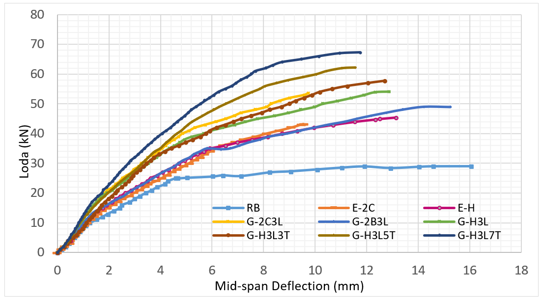
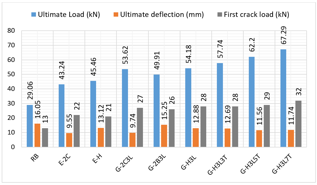
Figure 9 presents the load–deflection curves at midspan for all tested specimens. These include the RB and the strengthened beams. This curve provides a clear picture of the overall structural behavior, including the development of strength and the extent of deformation up to failure. In the initial loading stage, all specimens exhibited nearly linear elastic behavior. The associated curves were characterized by a steep slope, indicating high initial stiffness, reflecting a combined elastic response of the concrete and steel prior to the onset of initial cracking. As the load increased, cracking began to appear in the tensile zone, representing the second stage of behavior. In the final stage, a gradual decrease in the slope of the curve was observed due to a decrease in the effective stiffness of the section. Strengthening significantly increased the ultimate load. It also improved the post-cracking stiffness. This was attributed to the strengthening materials' contribution to the element’s ability to withstand tensile forces, which reduces stress concentration in the strengthening and delays the development of large cracks. The experimental results are summarized in Table 5 and illustrated in Figure 10.
Figure 9. Load-deflection curves
Figure 10. First crack, ultimate load, and deflection bar chart
Table 5. Experimental results
|
No. |
Spe. |
Pcr (KN) |
Pcr (%) |
Pu (KN) |
Pu (%) |
∆u (mm) |
∆u (%) |
Mode of Failure |
|
1 |
RB |
13. |
0.0 |
29.06 |
0.0 |
16.05 |
0.00 |
Flexural with crashing of concrete |
|
2 |
E-2C |
22 |
69.2 |
43.24 |
48.8 |
9.55 |
−40.50 |
Slight debonding followed by concrete cover separation |
|
3 |
E-H |
21 |
61.5 |
45.46 |
56.4 |
13.12 |
−18.26 |
Debonding followed by concrete cover separation |
|
4 |
G-2C3L |
27 |
107.7 |
53.62 |
84.5 |
9.74 |
−39.31 |
Concrete cover separation |
|
5 |
G-2B3L |
26 |
100.0 |
49.91 |
71.7 |
15.25 |
−4.98 |
Flexural with crashing of concrete |
|
6 |
G-H3L |
28 |
115.4 |
54.18 |
86.4 |
12.88 |
−19.75 |
Concrete cover separation |
|
7 |
G-H3L3T |
28 |
115.4 |
57.74 |
98.7 |
12.69 |
−20.93 |
Concrete cover separation |
|
8 |
G-H3L5T |
29 |
123.1 |
62.20 |
114.0 |
11.56 |
−27.98 |
Concrete cover separation |
|
9 |
G-H3L7T |
32 |
146.2 |
67.29 |
131.6 |
11.74 |
−26.85 |
Concrete cover separation |
3.1.1 Reference beam
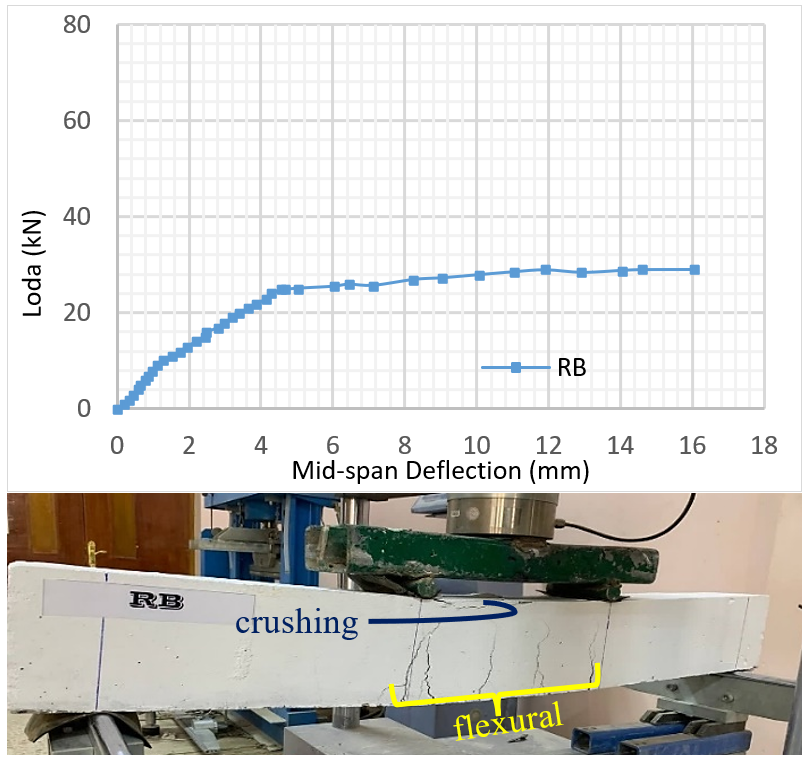
This is a reinforced and unstrengthened concrete beam, which showed a clear decrease in stiffness after cracking at a load of 13 kN. The load continued to increase at a slow rate until reaching an ultimate load of 29.06 kN, followed by a stage of gradual decrease in strength with continued increasing displacement until reaching a final deflection of 16.05 mm. This indicates relatively ductile behavior characterized by an extended softening stage prior to final failure in a flexural mode. This behavior can be attributed to the development of cracks and the subsequent yielding of the reinforcing steel, followed by crushing of the concrete in the compression zone, as illustrated in Figure 11.
Figure 11. Load-deflection curve and mode of failure (RB)
3.1.2 Beam (E-2C)
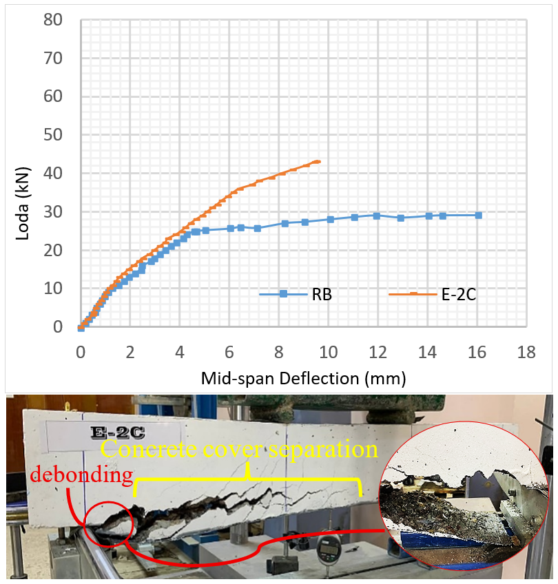
This beam was strengthened via EBR technology with two layers of CFRP. The curve in Figure 12 shows a significant improvement in structural performance compared to the RB. During the first stage, the elastic behavior was similar to that of the reference specimen, indicating the significance of the contribution of the concrete and reinforcing steel at this stage. The curve then gradually increases with a 69% delay in the appearance of the first crack. The curve subsequently becomes less steep, leading to failure at an ultimate load that was increased by more than 48% compared to the reference. This reflects the contribution of the strengthening to improving the load capacity until it was hindered by the failure of the strengthening with simple premature debonding and separation of the concrete cover. With this improvement, the final deflection was found to be decreased by more than 40%, indicating more sudden failure.
Figure 12. Load-deflection curve and mode of failure (E-2C)
3.1.3 Beam (E-H)
The load-deflection curve for specimen E-H shows a clear improvement in strength compared to the RB, with a 61% delay in the onset of the first crack and a 56% improvement in ultimate load. This indicates the contribution of the strengthening to withstanding tensile forces and reducing stress concentration in the reinforcement. Note the slight decrease of 18% in the final deformation, indicating that a fair amount of deflection occurred prior to failure, resulting from separation, followed by separation of the concrete cover, as illustrated in Figure 13.
Figure 13. Load-deflection curve and mode of failure (E-H)
3.1.4 Beam (G-2C3L)
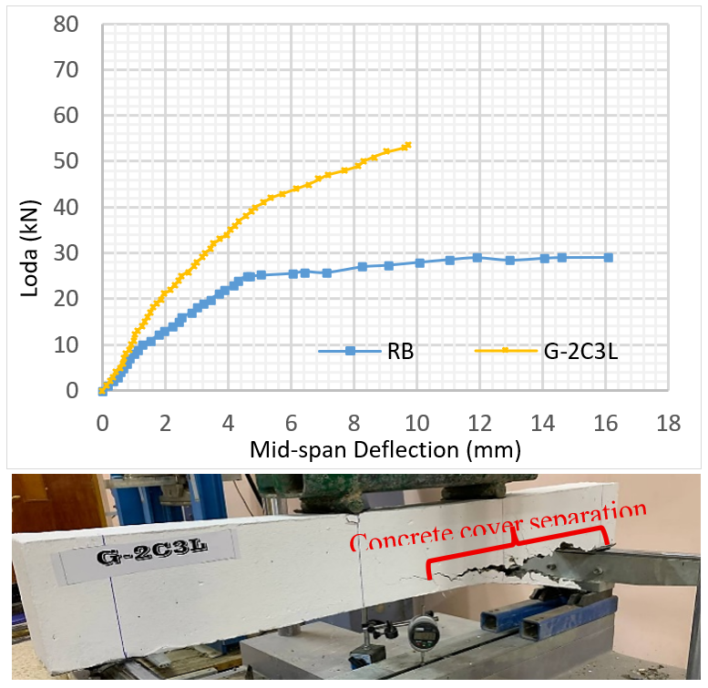
This beam was strengthened via the EBROG technique, employing three longitudinal grooves and two layers of CFRP. This technique significantly enhanced the structural performance, as evidenced by the increase in the first cracking load and ultimate load, delaying the onset of the first crack by more than 107%. The strengthening response became evident after this stage, as the curve height increased, resulting in an increase in the ultimate load of more than 84% compared to the RB. The observed increase is attributed to the enhanced tensile resistance provided by the strengthening system. This increase was accompanied by a sharp decrease in the final deformation, with the ultimate deflection decreasing by approximately 40%. Separation of the concrete cover was the ultimate failure mode of this specimen, as illustrated in Figure 14.
Figure 14. Load-deflection curve and mode of failure (G-2C3L)
3.1.5 Beam (G-2B3L)
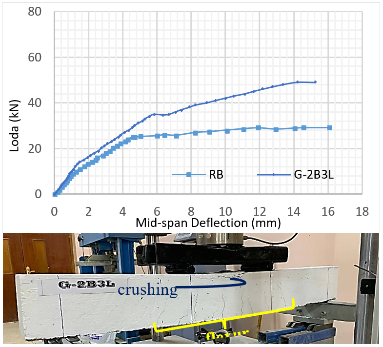
This beam was strengthened using two layers of BFRP via the EBROG technique and three longitudinal grooves. As shown in Figure 15, the specimen exhibited behavior comparable to that of the RB in terms of deformation capacity and failure mode. The ultimate deflection was remarkably similar, with a reduction of only 5% compared to the reference. The failure mode was the same as that for the RB: flexural failure with slight crushing in the compression zone. In addition to this desirable similarity in behavior, the flexural performance was also significantly improved, increasing the first crack and ultimate loads by 100% and 72%, respectively.
Figure 15. Load-deflection curve and mode of failure (G-2B3L)
3.1.6 Beam (G-H3L)
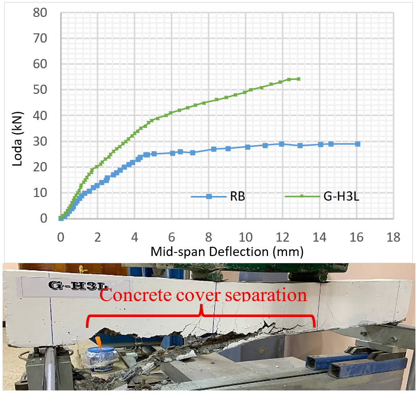
This beam utilizes hybrid strengthening materials with three longitudinal grooves. This strengthening delayed the first cracking load by 115% and the ultimate load by 86% compared to the RB, while achieving a final deflection of 12.88 mm, approximately 20% less than the RB. The failure mode was the separation of the concrete cover, starting from the strengthening end towards the middle, as shown in Figure 16.
Figure 16. Load-deflection curve and mode of failure (G-H3L)
3.1.7 Beam (G-H3L3T)
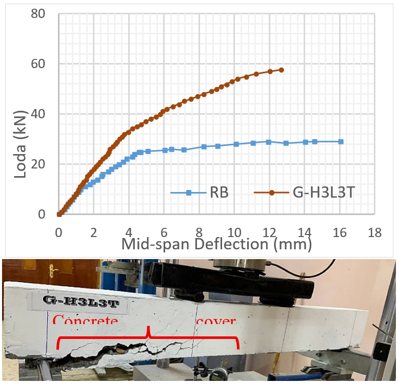
This beam was strengthened via the EBROG technique, employing three longitudinal and three transverse grooves distributed equally and with the use of HFRP. The strengthening contributed to increasing the load-carrying capacity, as it increased the first cracking load by 115%, while increasing ultimate load by 99%, but decreasing the ultimate deflection by approximately 21% compared to the RB. The failure pattern was the separation of the concrete cover from the edges of the strengthening to the middle, as illustrated in Figure 17.
Figure 17. Load-deflection curve and mode of failure (G-H3L3T)
3.1.8 Beam (G-H3L5T)
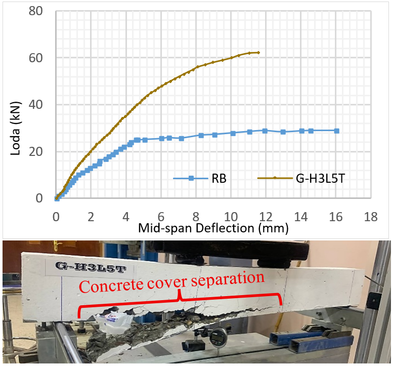
Five transverse grooves and three longitudinal grooves were used for HFRP strengthening. Improved stress transfer and bond performance were achieved. Concrete cover separation was observed at a relatively advanced loading stage when the ultimate load reached 62.2 kN, which was 114% higher than the RB. The load at first crack appearance was increased by 123%, and ultimate deflection decreased by 28%, as illustrated in Figure 18.
Figure 18. Load-deflection curve and mode of failure (G-2C3L5T)
3.1.9 Beam (G-H3L7T)
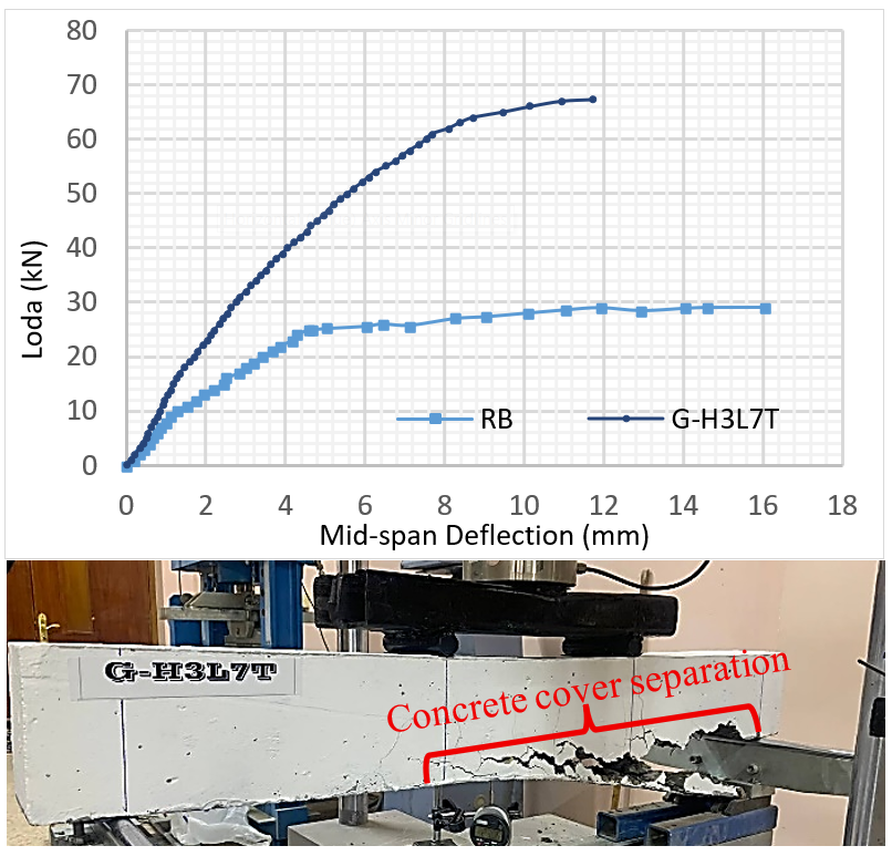
HFRP was used to strengthen this beam using the EBROG technique. Seven transverse grooves and three longitudinal grooves were provided. The highest first-crack load was recorded for this specimen, with a 146% increase compared to the RB. The ultimate load was found to have increased by more than 131%, and the final deflection decreased by approximately 27%. The failure mode was deep separation of the concrete cover. Figure 19 shows the load-deflection curve for beam G-H3L7T and its mode of failure.
Figure 19. Load-deflection curve and mode of failure (G-2C3L7T)
3.2 Ductility and stiffness
Ductility is the ability of a structural element to withstand significant deformation after reaching its yield point without sudden failure, while still maintaining its ability to resist loads. Stiffness is defined as the resistance of a structural element to deformation under the influence of loads. Given the importance of ductility in this study and the difficulty and imprecision in determining the yield point, the area under the curve (A), representing the extent of energy absorption before failure, was used as an indirect indicator of ductility. This was determined based on the limits of integration up to failure, which were determined along with the ultimate load from the stress-strain curve. The secant stiffness method was used to calculate the stiffness (K) [39].
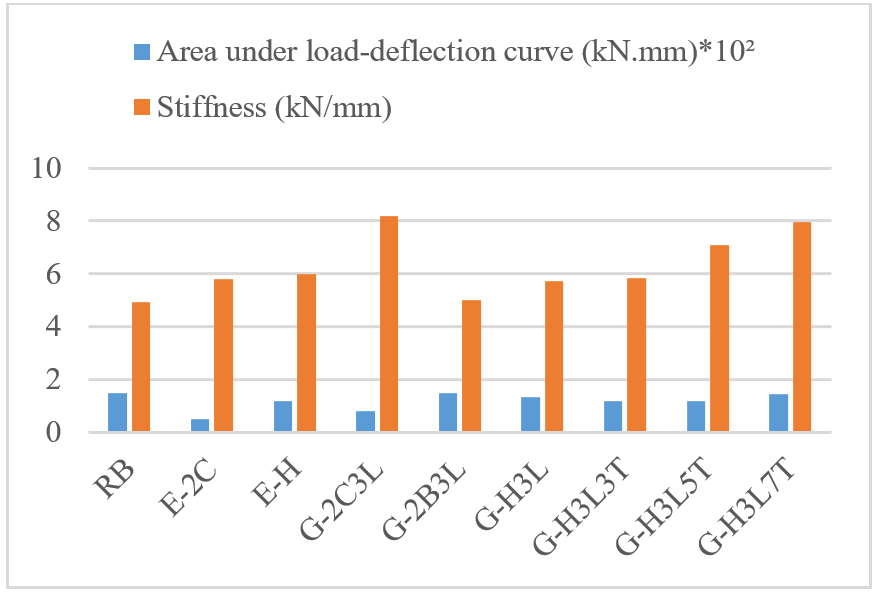
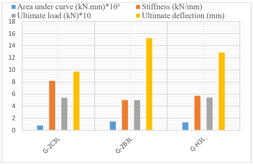
Table 6 and Figure 20 present the results for the area under the curve and stiffness. A reduction in the area under the load–deflection curve was observed in beams strengthened with CFRP. For beam E-2C, strengthened using the EBR technique, the area decreased by 67% compared with the RB. For beam G-2C3L, strengthened using the EBROG technique, the reduction was limited to 47%. These results indicate that EBROG partially improved the ductility loss associated with CFRP strengthening. This indicates a decrease in ductility when strengthening with CFRP due to the material's nature and the brittle behavior of carbon fiber, while ductility was somewhat improved by EBROG. The area under the curve approached that of the RB, with a difference of only 1% for beam G-2B3L due to the use of two BFRP layers, which have greater ductility than CFRP. As for the HFRP-strengthened beams, their load-deflection curves showed a slight decrease in area, 21% for beam E-H, while the area under the curve approached that of the RB for the EBROG-strengthened beams, with decreases ranging between 3% and 21%. The stiffness of all the strengthened beams was found to be significantly improved. EBR strengthening resulted in a 21% increase in stiffness, while the EBROG strengthening technique resulted in an even greater increase. Further strengthening of the technique led to increased stiffness, with beam G-H3L7T achieving a 61% increase. In contrast, the stiffness of beam G-2B3L improved by only 2% when using BFRP alone, while beam G-2C3L realized a 66% increase due to the superior stiffness of carbon fiber.
Table 6. Area under the curve and stiffness results
|
Specimens |
A (kN·mm) |
K (kN·mm) |
A/A_RB |
K/K_RB |
|
RB |
147.70 |
4.93 |
1.00 |
1.00 |
|
E-2C |
48.10 |
5.78 |
0.33 |
1.17 |
|
E-H |
116.70 |
5.97 |
0.79 |
1.21 |
|
G-2C3L |
78.86 |
8.20 |
0.53 |
1.66 |
|
G-2B3L |
146.80 |
5.02 |
0.99 |
1.02 |
|
G-H3L |
132.50 |
5.73 |
0.90 |
1.16 |
|
G-H3L3T |
117.70 |
5.83 |
0.80 |
1.18 |
|
G-H3L5T |
116.90 |
7.08 |
0.79 |
1.44 |
|
G-H3L7T |
143.70 |
7.96 |
0.97 |
1.61 |
Figure 20. Area under curve and stiffness results bar chart
3.3 Study variables
3.3.1 Effect of strength technique
Under the present test conditions, EBROG provided higher cracking and ultimate loads than EBR. For example, the first-crack load increased from 22 kN in beam E-2C to 27 kN in beam G-2C3L, while the ultimate load increased from 43.24 kN to 53.62 kN. The superiority of EBROG was also reflected in stiffness and ductility. Both parameters improved when the same CFRP strengthening material was used. Similar behavior was observed for beams E-H and G-H3L. In contrast, the strengthening technique had little influence on the ultimate deflection.
3.3.2 Effect of the type of strengthening material
The difference in performance was clearly evident and was due to the different strengthening materials used. CFRP is known to have high tensile strength and low elongation [39], while BFRP has lower tensile strength than carbon fiber but greater elongation [29, 34]. These properties were clearly reflected in the structural performance of the tested beams. A clear difference was observed among beams G-2C3L, G-2B3L, and G-H3L. The BFRP-strengthened beam exhibited the lowest ultimate load. However, it achieved the highest ultimate deflection and showed superior ductility. In addition, its stiffness was lower than that of the CFRP-strengthened beam. The beam strengthened with carbon fiber alone exhibited the least deformation prior to failure, the greatest stiffness, and the lowest ductility. The beam strengthened with hybrid fiber combined high load capacity, suitable deflection, ductility, and stiffness. Although these three beams had the same interface conditions, this difference was due to the different materials used. These results fulfilled the primary objective of the study and demonstrated the effectiveness of the proposed strengthening approach; further, it encourages the use of basalt fiber with carbon fiber due to its good structural performance, and reduces the cost of strengthening due to the low cost of producing basalt [29]. Figure 21 compares the structural performance of beams strengthened with CFRP, BFRP, and HFRP systems.
Figure 21. Effect of the type of material used
3.3.3 Effect of adding transverse grooves
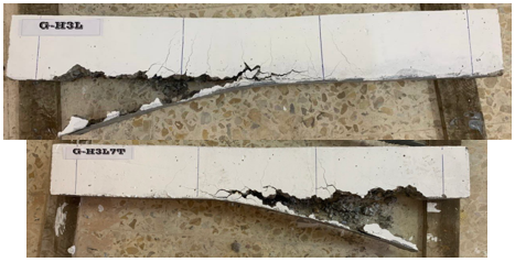
Transverse grooves were introduced to enhance the effectiveness of the EBROG technique. They improved stress distribution and increased the interaction area between the strengthening system and the concrete substrate. This observation was supported by the greater depth of concrete cover separation, as shown in Figure 22.
Figure 22. Cover separation depth for G-H3L, G-H3L7T
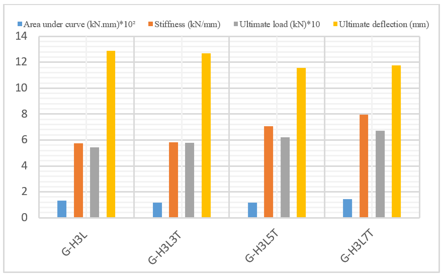
Figure 23. Effect of adding transverse grooves
The addition of transverse grooves resulted in a progressive increase in ultimate load. The load capacity increased from 54.18 kN for beam G-H3L to 57.74 kN, 62.20 kN, and 67.29 kN for beams G-H3L3T, G-H3L5T, and G-H3L7T, respectively. Ultimate deflection and ductility were not significantly affected by the number of grooves. However, stiffness improved as the number of transverse grooves increased, indicating enhanced strengthening efficiency. Figure 23 presents a comparison of the effects of transverse grooves on beam performance.
The conclusions presented in this study are limited to the investigated specimens and test conditions. Different beam dimensions, material properties, and strengthening configurations may lead to different outcomes. However, they provide an important insight into the performance of strengthening under the influence of the studied variables.
|
RC |
reinforced concrete |
|
FRP |
fiber-reinforced polymer |
|
CFRP |
carbon fiber-reinforced polymer |
|
BFRP |
basalt fiber-reinforced polymer |
|
HFRP |
hybrid fiber-reinforced polymer |
|
EBR |
externally bonded reinforcement |
|
EBROG |
externally bonded reinforcement on groove |
|
Pcr |
first crack load |
|
Pu |
ultimate load |
|
∆u |
ultimate deflection |
|
A |
area under curve |
|
K |
stiffness |
[1] Nguyen, D.M., Chan, T.K., Cheong, H.K. (2001). Brittle failure and bond development length of CFRP-concrete beams. Journal of Composites for Construction, 5(1): 12-17. https://doi.org/10.1061/(ASCE)1090-0268(2001)5:1(12)
[2] De Lorenzis, L., Teng, J.G. (2007). Near-surface mounted FRP reinforcement: An emerging technique for strengthening structures. Composites Part B: Engineering, 38(2): 119-143. https://doi.org/10.1016/j.compositesb.2006.08.003
[3] El-Gamal, S., Al-Salloum, Y., Alsayed, S., Aqel, M. (2012). Performance of near surface mounted glass fiber reinforced polymer bars in concrete. Journal of Reinforced Plastics and Composites, 31(22): 1501-1515. https://doi.org/10.1177/0731684412464088
[4] Soliman, S.M., El-Salakawy, E., Benmokrane, B. (2011). Bond performance of near-surface-mounted FRP bars. Journal of Composites for Construction, 15(1): 103-111. https://doi.org/10.1061/(ASCE)CC.1943-5614.0000150
[5] Sharaky, I.A., Torres, L., Comas, J., Barris, C. (2014). Flexural response of reinforced concrete (RC) beams strengthened with near surface mounted (NSM) fibre reinforced polymer (FRP) bars. Composite Structures, 109: 8-22. https://doi.org/10.1016/j.compstruct.2013.10.051
[6] El Gamal, S.E., Al Nuaimi, A., Al-Saidy, A., Al-Shanfari, K. (2019). Flexural behavior of RC beams strengthned with CFRP sheets using different strengthening techniques. Journal of Engineering Research, 16(1): 35-43. https://doi.org/10.24200/tjer.vol16iss1pp35-43
[7] Toutanji, H., Zhao, L., Zhang, Y. (2006). Flexural behavior of reinforced concrete beams externally strengthened with CFRP sheets bonded with an inorganic matrix. Engineering Structures, 28(4): 557-566. https://doi.org/10.1016/j.engstruct.2005.09.011
[8] Li, Y.F., Xie, Y.M., Tsai, M.J. (2009). Enhancement of the flexural performance of retrofitted wood beams using CFRP composite sheets. Construction and Building Materials, 23(1): 411-422. https://doi.org/10.1016/j.conbuildmat.2007.11.005
[9] Hawileh, R.A., Rasheed, H.A., Abdalla, J.A., Al-Tamimi, A.K. (2014). Behavior of reinforced concrete beams strengthened with externally bonded hybrid fiber reinforced polymer systems. Materials & Design, 53: 972-982. https://doi.org/10.1016/j.matdes.2013.07.087
[10] Al-Saidy, A.H., Saadatmanesh, H., El-Gamal, S., Al-Jabri, K.S., Waris, B.M. (2016). Structural behavior of corroded RC beams with/without stirrups repaired with CFRP sheets. Materials and Structures, 49(9): 3733-3747. https://doi.org/10.1617/s11527-015-0751-y
[11] Lavorato, D., Bergami, A.V., Fiorentino, G., Fiore, A., Santini, S., Nuti, C. (2018). Experimental tests on existing RC beams strengthened in flexure and retrofitted for shear by C-FRP in presence of negative moments. International Journal of Advanced Structural Engineering, 10(3): 211-232. https://doi.org/10.1007/s40091-018-0193-1
[12] Fareed, S. (2014). Behaviour of reinforced concrete beams strengthened by CFRP wraps with and without end anchorages. Procedia Engineering, 77: 123-130. https://doi.org/10.1016/j.proeng.2014.07.011
[13] Sattarifar, A.R., Sharbatdar, M.K., Dalvand, A. (2015). RC connections strengthened with FRP sheets using grooves on the surface. International Journal of Civil Engineering, 13(4): 432-443. https://doi.org/10.22068/IJCE.13.4.432
[14] Yuan, C., Chen, W.S., Pham, T.M., Chen, L., Cui, J., Shi, Y.C., Hao, H. (2019). Effect of aggregate size on the dynamic interfacial bond behaviour between basalt fiber reinforced polymer sheets and concrete. Construction and Building Materials, 227: 116584. https://doi.org/10.1016/j.conbuildmat.2019.07.310
[15] Yuan, C., Chen, W.S., Pham, T.M., Hao, H., Cui, J., Shi, Y.C. (2020). Influence of concrete strength on dynamic interfacial fracture behaviour between fibre reinforced polymer sheets and concrete. Engineering Fracture Mechanics, 229: 106934. https://doi.org/10.1016/j.engfracmech.2020.106934
[16] Mostofinejad, D., Mahmoudabadi, E. (2010). Grooving as alternative method of surface preparation to postpone debonding of FRP laminates in concrete beams. Journal of Composites for Construction, 14(6): 804-811. https://doi.org/10.1061/(ASCE)CC.1943-5614.0000117
[17] Mashrei, M.A., Makki, J.S., Sultan, A.A. (2019). Flexural strengthening of reinforced concrete beams by carbon fiber reinforced polymer (CFRP) sheets with grooves. Latin American Journal of Solids and Structures, 16(4): 1-13. https://doi.org/10.1590/1679-78255514
[18] Mostofinejad, D., Shameli, S.M., Hosseini, A. (2012). Experimental study on the effectiveness of EBROG method for flexural strengthening of RC beams. In the 6th International Conference on FRP Composites in Civil Engineering (CICE 2012), Rome, Italy.
[19] Abed, R.J., Mashrei, M.A., Sultan, A.A. (2022). Flexural behavior of reinforced concrete beams strengthened by carbon fiber reinforced polymer using different strengthening techniques. Advances in Structural Engineering, 25(2): 355-373. https://doi.org/10.1177/13694332211049992
[20] Han, Z.H., Gao, J., Song, H.H., Xu, G.Y. (2024). Bond properties of CFRP externally bonded reinforcement on groove in concrete. International Journal of Concrete Structures and Materials, 18(1): 32. https://doi.org/10.1186/s40069-024-00678-9
[21] Qassim, H.J., Mashrei, M.A. (2024). Flexural strength of RC continuous beams strengthened by CFRP using EBR and EBROG methods: Experimental and analytical study. Civil and Environmental Engineering, 20(1): 580-592. https://doi.org/10.2478/cee-2024-0044
[22] Nurbaiah, M.N., Hanizah, A.H., Farhana, I.N. (2014). Flexural behavior of reinforced concrete (RC) beams with externally bonded (EB) carbon fiber reinforced polymer (CFRP) sheets. In InCIEC 2013: Proceedings of the International Civil and Infrastructure Engineering Conference 2013, pp. 637-648. https://doi.org/10.1007/978-981-4585-02-6_55
[23] Maid, A.A., Mashrei, M.A. (2025). Investigation the behavior fibrous-RC beams strengthening by CFRP on grooves with different compressive strengths of concrete. Revue des Composites et des Matériaux Avancés-Journal of Composite and Advanced Materials, 35(4): 697-707. https://doi.org/10.18280/rcma.350412
[24] Abdalla, J.A., Abu-Obeidah, A.S., Hawileh, R.A., Rasheed, H.A. (2016). Shear strengthening of reinforced concrete beams using externally-bonded aluminum alloy plates: An experimental study. Construction and Building Materials, 128: 24-37. https://doi.org/10.1016/j.conbuildmat.2016.10.071
[25] Saleem, M.U., Qureshi, H.J., Amin, M.N., Khan, K., Khurshid, H. (2019). Cracking behavior of RC beams strengthened with different amounts and layouts of CFRP. Applied Sciences, 9(5): 1017. https://doi.org/10.3390/app9051017
[26] Rabinovitch, O., Frostig, Y. (2003). Experiments and analytical comparison of RC beams strengthened with CFRP composites. Composites Part B: Engineering, 34(8): 663-677. https://doi.org/10.1016/S1359-8368(03)00090-8
[27] Ashour, A.F., El-Refaie, S.A., Garrity, S.W. (2004). Flexural strengthening of RC continuous beams using CFRP laminates. Cement and Concrete Composites, 26(7): 765-775. https://doi.org/10.1016/j.cemconcomp.2003.07.002
[28] Mostofinejad, D., Shameli, S.M., Hosseini, A. (2014). EBROG and EBRIG methods for strengthening of RC beams by FRP sheets. European Journal of Environmental and Civil Engineering, 18(6): 652-668. https://doi.org/10.1080/19648189.2014.900523
[29] Sim, J., Park, C., Moon, D.Y. (2005). Characteristics of basalt fiber as a strengthening material for concrete structures. Composites Part B: Engineering, 36(6-7): 504-512. https://doi.org/10.1016/j.compositesb.2005.02.002
[30] Siddika, A., Al Mamun, M.A., Alyousef, R., Amran, Y.H.M. (2019). Strengthening of reinforced concrete beams by using fiber-reinforced polymer composites: A review. Journal of Building Engineering, 25: 100798. https://doi.org/10.1016/j.jobe.2019.100798
[31] Kadhim, S., Özakça, M. (2022). Flexural performance of RC beams externally strengthened with a single-layer of basalt fiber reinforced polymer sheets. Composites and Advanced Materials, 31: 26349833221102471. https://doi.org/10.1177/26349833221102471
[32] Lin, B.X., Chun, Q., Mi, Z.D. (2024). Flexural behavior of historical RC beams strengthened with hybrid FRP sheets. Case Studies in Construction Materials, 20: e03410. https://doi.org/10.1016/j.cscm.2024.e03410
[33] Choobbor, S.S., Hawileh, R.A., Abu-Obeidah, A., Abdalla, J.A. (2019). Performance of hybrid carbon and basalt FRP sheets in strengthening concrete beams in flexure. Composite Structures, 227: 111337. https://doi.org/10.1016/j.compstruct.2019.111337
[34] Basalt UD Fabric – Technical Datasheet. Jiujiang Yaray Composite Material Co., Ltd., China. http://www.yaray.com.cn/.
[35] ASTM C150/C150M-19. (2019). Standard Specification for Portland Cement. ASTM International. https://doi.org/10.1520/C0150_C0150M-19
[36] ASTM C33/C33M-08. (2018). Standard Specification for Concrete Aggregates. ASTM International. https://doi.org/10.1520/C0033_C0033M-08
[37] Sikadur®-330 Product Data Sheet. (2025). https://usa.sika.com/content/dam/dms/us01/0/sikadur_-330.pdf.
[38] SikaWrap®-300 C. (2023). Woven unidirectional carbon fiber fabric, designed for structural strengthening applications as part of the Sika® strengthening system. https://phl.sika.com/en/construction/structural-strengthening/frp-fabrics/sikawrap-300-c.html.
[39] Park, P. (1989). Evaluation of ductility of structures and structural assemblages from laboratory testing. Bulletin of the New Zealand Society for Earthquake Engineering, 22(3): 155-166. https://doi.org/10.5459/bnzsee.22.3.155-166