Yiyun Yang
© 2021 IIETA. This article is published by IIETA and is licensed under the CC BY 4.0 license (http://creativecommons.org/licenses/by/4.0/).
OPEN ACCESS
Slope instability may be caused by the action of external load or the lack of internal shear strength. The traditional limit equilibrium method cannot accurately calculate the safety coefficient of slopes enhanced by fiber-reinforced cement piles. Few scholars have discussed the anti-slip property, structural form, and design calculation of fiber-reinforced composite cement piles. Therefore, this paper chooses to analyze the influence of basalt fiber-reinforced cement-based composite (BFRCBC) on slope stability. On the one hand, the authors analyzed the anti-crack mechanism of BFRCBC: the strength analysis was carried out by the rule of mixtures, the anti-crack analysis was implemented by the fiber spacing theory, and the entire anti-crack process was discussed in details. On the other hand, the authors constructed a slope model, and performed the relevant stability analysis. Experimental results show that the BFRCBC cement piles can effectively enhance the stability of the slope.
basalt fiber, composite, slope reinforcement, stability analysis
Slope is the most common form in engineering construction. Under natural and human interferences, some instable slopes will suffer from landslide, slump, collapse, or spalling, and evolve into a geological disaster that threatens lives and properties [1-3]. Slope instability is mainly caused by the action of external load or the lack of internal shear strength [4-6]. Capable of enhancing slope stability, fiber-reinforced composite cement piles have attracted more and more attention from scholars.
Researchers from different fields have researched extensively into the stability of pure soil slopes, and obtained various effective research methods [7-9]. Rusydy et al. [10] explored the properties and change laws of compaction, strength, and deformation of remolded cement-modified soil with different mix ratios, water contents, and compactness, carried out grey correlation analysis and numerical simulation of factors affecting slope stability, and optimized the mix ratio of cement-modified soil that maximizes the stability of high fill slope.
The stability of tall and long slopes is threated by the silty clay, fill soil and unstable rock-soil layers [11-14]. There is not yet a unified code for the stability evaluation criteria of cement pile-reinforced slopes. To fill the gap, Dassanayake et al. [15] analyzed the strength and deformation features of cement pile-reinforced slopes in terms of uniaxial compression, radial splitting, and triaxial compression, and applied the limit equilibrium method and finite-element strength reduction to the numerical simulation of anti-sliding mechanism of such slopes.
Deep mixing or high-pressure jet grouting have been widely used to prepare the cement piles for reinforcement of foundation pits, slopes, and embankments [16-21]. De Vita et al. [22] constructed a horizontal shear test model for concrete pile composite foundation with a geometric similarity constant of 15:1, and conducted simplified calculation of overall stability and shear strength comparison of discrete cement soil piles and cement soil shear walls. Ramer et al. [23] introduced support vector machine (SVM), particle swarm optimization (PSO), and strength reduction method to optimize the design variables of the shear walls for cement concrete-reinforced slopes, and guaranteed the safety and stability of the slopes at the same time. Focusing on ecological permeable concrete with numerous pores and voids, Chang et al. [24] evaluated the overall protection and greening functions of the concrete in slope protection, and designed the concrete mix ratio meeting the application standards. Based on material mechanics method and finite-element method, Pang et al. [25] analyzed the slope stability and deformation of concrete gravity dams under different conditions, evaluated the seismic safety of each dam through compressive and tensile strength tests, and determined the stability safe coefficient (SSC) of concrete gravity dams under each condition.
Currently, there is no unified code for stability analysis on cement pile-reinforced slopes. Few scholars have discussed the anti-slip property, structural form, and design calculation of fiber-reinforced composite cement piles. In addition, the traditional limit equilibrium method cannot accurately calculate the safety coefficient of slopes enhanced by fiber-reinforced cement piles.
Therefore, this paper chooses to analyze the influence of basalt fiber-reinforced cement-based composite (BFRCBC) on slope stability. Specifically, Section 2 analyzes the anti-crack mechanism of BFRCBC: the strength analysis was carried out by the rule of mixtures, the anti-crack analysis was implemented by the fiber spacing theory, and the entire anti-crack process was discussed in details. Section 3 sets up a slope model, and completes the relevant stability analysis. Experimental results show that the BFRCBC cement piles can effectively enhance the stability of the slope.
2.1 Strength analysis
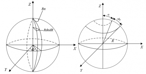
Slope stability is greatly affected by the physical-mechanical properties of the reinforced cement piles. The mixture of basalt fibers effectively improves the crack resistance of the piles. In actual slope projects, the basalt fibers are distributed in various directions across the cement matrix. Figure 1 shows the three-dimensional distribution of the fibers. To deeply explore the anti-crack mechanism of BFRCBC, this paper proposes the rule of mixtures for this composite.
Figure 1. Three-dimensional distribution of the basalt fibers
Let SQW, ΦQW, and TMQW be the stressed area, stress, and elastic modulus of basalt fibers, respectively; SJT, ΦJT, and TMJT be the stressed area, stress, and elastic modulus of cement matrix, respectively; SFH, ΦFH, and TMFH be the stressed area, stress, and elastic modulus of BFRCBC, respectively; ηQW and ηJT be the volume fractions of basalt fibers and cement matrix in BFRCBC, respectively; ΦFD be the tensile strength of BFRCBC; ΦQD* and ΦJT* be the tensile stresses at break of basalt fibers and cement matrix, respectively.
Suppose basalt fibers, cement matrix, and BFRCBC have the same strains (ρQW=ρJT=ρFH). Then, ρQW, ρJT, and ρFH satisfy ΦFH=TMFH+ρFH, ΦQW=TMQW+ρQW, and ΦJT=TMJT+ρJT. Then, the strength of randomly distributed BFRCBC can be derived as:
${{\Phi }_{FD}}={{\psi }_{j}}{{\Phi }_{QD}}{{\eta }_{QW}}+\Phi _{JT}^{'}\left( 1-{{\eta }_{QW}} \right)$ (1)
The elastic modulus of BFRCBC can be calculated by:
$T{{M}_{FH}}={{\psi }_{j}}T{{M}_{QW}}{{V}_{QW}}+T{{M}_{JT}}\left( 1-{{V}_{QW}} \right)$ (2)
Let δα be the directional coefficient of basalt fibers; δQJ be the bond coefficient between basalt fibers and cement matrix; δQW be the effective length coefficient of basalt fibers. Then, the composite effective coefficient ψj related to all these three coefficients can be expressed as:
${{\psi }_{j}}={{\delta }_{\alpha }}{{\delta }_{QJ}}{{\delta }_{QW}}$ (3)
The calculation methods of δα, δQJ, and δQW are detailed as follows. Based on the equal probability theory of fibers, it is assumed that the fibers farther from the edge of BFRCBC, which has been fully stirred during molding, are distributed in various directions across the cement matrix. Then, the directional coefficient δα that characterizes the distribution state of basalt fibers in cement matrix can be equivalent to the proportion of the basalt fibers in the stress direction of the cement matrix. Suppose the length of a basalt fiber equals the diameter R of the three-dimensional spherical space. Then, the probability that the basalt fiber falls on the position where its angle from the b-axis and the axis is α can be calculated by:
$\frac{{{R}^{2}}sin\alpha d\psi }{2\pi {{R}^{2}}}=\frac{1}{2\pi }sin\alpha d\psi $ (4)
Figure 2. Stress-strain situation of BFRCBC
Figure 2 shows the stress-strain situation of BFRCBC. Taking the tensile stress direction of the composite as the positive direction of a-axis, δα can be calculated by:
${{\eta }_{\theta }}=\int_{0}^{\pi }{\int_{0}^{\frac{\pi }{2}}{\frac{1}{2\pi }}\sin \theta \cos \theta d\theta =0.5} \\ {{\delta }_{\alpha }}=\int_{0}^{\pi }{\int_{0}^{\frac{\pi }{2}}{\frac{1}{2\pi }}\sin \alpha \cos \alpha d\alpha =0.5}$ (5)
δQJ mainly characterizes the bonding strength between basalt fibers and cement matrix. Let kR, ΦQD, and RB be the length, ultimate tensile strength, and diameter of basalt fibers, respectively; σ be the mean shear stress on the bonding surface between basalt fibers and cement matrix. Suppose minimum length of the shear zone where a basalt fiber is broken is half the critical fiber length kQJ. If the tensile stress on BFRCBC is in equilibrium with the bonding stress between basalt fibers and cement matrix, then:
$\frac{1}{\text{2}}\sigma \pi {{R}_{B}}{{k}_{QJ}}=\frac{1}{4}{{\Phi }_{QD}}\pi R_{B}^{2}$ (6)
kQJ, which limits the deformation of basalt fibers can be calculated by
${{k}_{QJ}}=\frac{1}{2\sigma }{{\Phi }_{QD}}{{R}_{B}}$ (7)
Let ΦQW be the maximum tensile stress applied to pull out basalt fibers from cement matrix. Then, the ratio of ΦQW to ΦQD can be defined as:
${{\delta }_{QJ}}=\frac{{{\Phi }_{QW}}}{{{\Phi }_{QD}}}$ (8)
Dependent on fiber type and bond length, the bond coefficient changes with stress. Basalt fibers cannot exert their full effect, when the length kR is smaller than kQJ. Once the cement matrix of BFRCBC is broken, the maximum tensile strength of basalt fibers in the positive direction can be calculated by:
${{\Phi }_{QW}}=2\sigma \frac{{{k}_{R}}}{{{R}_{B}}}$ (9)
The corresponding bond coefficient δQJ can be calculated by:
${{\delta }_{QJ}}=\frac{2\sigma \frac{{{k}_{R}}}{{{R}_{B}}}}{{{\Phi }_{QD}}}=2\sigma \frac{{{k}_{QW}}}{{{R}_{B}}{{\Phi }_{QD}}}$ (10)
If kR>kQJ, the ΦQW after the cement matrix of BFRCBC is broken can be calculated by:
${{\Phi }_{QW}}={{\Phi }_{QD}}$ (11)
Combining formulas (11) and (10):
${{\delta }_{QJ}}=\frac{{{\Phi }_{QW}}}{{{\Phi }_{QD}}}=1$ (12)
The above analysis shows that, basalt fibers can fully exert their bonding effect if kR>kQJ, making the composite denser.
It can be proved that basalt fibers are more likely to be pulled out from the cement matrix, if the buried depth kBL is smaller than kQJ. To obtain the exact value of δQW, it is assumed that the fracture surface of BFRCBC is perpendicular to a fiber. Let a be the length of the shorter end of the fiber embedded into the matrix. Then, δα and δQJ determine the maximum tensile stress that the fiber can withstand, which falls in [0, δαδQJΦQD]. Then, δQW must satisfy:
$\frac{{{\delta }_{QW}}}{{{\delta }_{\alpha }}{{\delta }_{QJ}}{{\Phi }_{QD}}}=\frac{2a}{{{k}_{BL}}}$ (13)
It is known that the maximum tensile stress that the fiber can withstand falls in [0, δαδQJΦQD] with a probability of 2da/kBL, and appears at any position of the space with an equal probability. Thus, δQW can be simplified as:
${{\delta }_{QW}}=\int_{0}^{0.5}{\frac{2a}{{{k}^{2}}}}da=0.5$ (14)
If kBL>kQJ, the reinforcement effect of the basalt fiber varies, due to the changing relative position between the facture surface and the fiber. When the two intersects within the range of [kR, kQJ] at the middle, the probability for the fiber to appear at any position in the space is 2da/kR, and its reinforcement effect equals 1. Then, δQW can be calculated by:
${{\delta }_{QW}}=\int_{0}^{0.5}{\frac{4ada}{{{k}_{R}}{{k}_{QJ}}}}+\int_{\frac{{{k}_{QJ}}}{2}}^{0.5}{\frac{2da}{{{k}_{R}}}}=1-0.5\frac{{{k}_{QJ}}}{{{k}_{R}}}$ (15)
When the cement matrix of BFRCBC cracks, the basalt fibers need to bear all the load. Let ρJD and ΦJD be the ultimate strain and ultimate tensile strength of cement matrix, respectively. Considering δα, δQJ, and δQW, when the volume fraction ηBL of basalt fibers is smaller than the critical volume fraction ηQJ, the ultimate tensile strength ΦFD of BFRCBC can be calculated by:
$\begin{align} & {{\Phi }_{FD}}={{\delta }_{\alpha }}{{\delta }_{QJ}}{{\delta }_{QW}}{{\rho }_{JD}}T{{M}_{BL}}{{\eta }_{QJ}}+{{\Phi }_{JD}}\left( 1-{{\eta }_{QJ}} \right) \\ & ={{\psi }_{j}}{{\rho }_{JD}}T{{M}_{BL}}{{\eta }_{QJ}}+{{\Phi }_{JD}}\left( 1-{{\eta }_{QJ}} \right) \\ \end{align}$ (16)
When ηBL>ηQJ, ΦFD can be calculated by:
${{\Phi }_{FD}}={{\delta }_{\alpha }}{{\delta }_{QJ}}{{\delta }_{QW}}{{\rho }_{JD}}T{{M}_{QW}}{{\eta }_{QJ}}$ (17)
The critical volume fraction ηQJ can be calculated by:
${{\eta }_{QJ}}=\frac{{{\Phi }_{JD}}}{{{\psi }_{j}}\left( {{\Phi }_{QD}}-{{\rho }_{JD}}T{{M}_{BL}} \right)+{{\Phi }_{JD}}}$ (18)
2.2 Anti-crack analysis
The crack resistance of basalt fibers on the cracking of BFRCBC is greatly affected by the mean spacing between fibers. Let LEF be the critical stress intensity factor of BFRCBC; γ be the crack shape coefficient; H be the mean fiber spacing. Then, the initial cracking tensile strength of BFRCBC can be calculated by:
$\Phi _{SN}^{SG}=\frac{{{L}_{EF}}}{\gamma \sqrt{H}}$ (19)
Formula (19) shows that H is negatively correlated with ΦSNSG. Suppose there are MBF basalt fibers per unit area perpendicular to the stress direction. Then, H can be calculated by:
$H=\sqrt{{}^{1}/{}_{{{M}_{BF}}}}$ (20)
MBF can be calculated by:
${{M}_{BF}}={{\eta }_{BL}}/\frac{\pi R_{B}^{2}}{4}{{k}_{BL}}=\frac{4{{\eta }_{BL}}}{\pi R_{B}^{2}{{k}_{BL}}}$ (21)
Considering δα, formula (21) can be rearranged into:
$\frac{{{M}_{BF}}}{{{\delta }_{\alpha }}{{k}_{BL}}}=\frac{4{{\eta }_{BL}}}{\pi R_{B}^{2}{{k}_{BL}}}\text{ }i.e.,\text{ }{{M}_{BF}}=\frac{4{{\eta }_{BL}}{{\delta }_{\alpha }}}{\pi R_{B}^{2}}$ (22)
Combining formulas (20) and (22):
$H=0.89{{R}_{B}}\sqrt{\frac{1}{{{\delta }_{\alpha }}{{\eta }_{BL}}}}$ (23)
Thus, H is jointly determined by RB, δα, and ηBL. To optimize the anti-crack effect of basalt fibers, it is necessary to minimize RB, and maximize ηBL and δα.
2.3 Anti-crack process
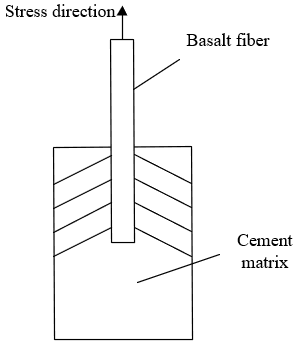
To reveal the influence mechanism of BFRCBC’s crack resistance on slope stability, a cracked cement pile reinforced by basalt fibers was taken as an example. Figure 3 shows the anti-crack process of fiber-reinforced cement pile. The pile breakage was considered as the breaking of the basalt fiber and the work of the external force T. Then, the relationship between the work of external force WOF, energy consumption of cement matrix WSN, and energy consumption of the fiber WCS can be described as:
$G_{A}=G_{C}+G_{F} W_{O F}=W_{S N}+W_{C S}$ (24)
Figure 3. Anti-crack process of fiber-reinforced cement pile
Let WES, WSD, and WST be the surface energy of crack propagation, the strain energy produced by the deformation of cement matrix, and the plastic deformation energy generated by the deformation, respectively. As the smallest term among the three, WST can be treated as a constant in crack propagation. Then, WSN can be described as:
${{W}_{SN}}={{W}_{ES}}+{{W}_{SD}}+{{\text{W}}_{ST}}$ (25)
Let WDQ and WQB be the energy consumptions of the fiber breaking away from the crack surface and the fiber breakage, respectively. Then, WCS can be described as:
${{W}_{CS}}={{W}_{DQ}}+{{W}_{QB}}$ (26)
To sum up, the relationship between the work of external force and the energy consumption of each part throughout cement pile breakage can be expressed as:
${{G}_{C}}={{G}_{SC}}+{{G}_{VC}}+{{\text{G}}_{PC}}+GSF+\text{ }{{\text{G}}_{\text{FF}}} \\ {{W}_{SN}}={{W}_{ES}}+{{W}_{SD}}+{{W}_{ST}}+{{W}_{DQ}}+ {{W}_{QB}}$ (27)
The whole process from crack propagation to cement pile breakage can be divided into five stages: incubation, generation, expansion, penetration, and breaking. It is assumed that the expansion and penetration stages are a unified whole with coordinated deformation, and the fibers solely bear all the external force for crack propagation. Eventually, the fibers break away from the upper and lower surfaces of the cement matrix. Let ΦTS and kL be the tensile strength and stick-off length of fibers, respectively; TMBL be the elastic modulus of basalt fibers. Then, the energy consumption WDQ of the fibers in the unified stage can be calculated by:
${{G}_{SF}}=\frac{\sigma _{F}^{2}{{\text{l}}_{d}}}{2{{E}_{F}}}\pi r_{F}^{2} \\ {{W}_{DQ}}=\frac{\Phi _{TS}^{2}{{k}_{L}}}{2T{{M}_{BL}}}\pi R_{B}^{2}$ (28)
Hence, WDQ is positively correlated with ΦTS, kL, and RB, and negatively with TMBL. The above analysis shows that the anti-crack effect of basalt fibers on BFRCBC can be likened to an energy transmission process, in which the fibers are pulled out or broken after the energy consumption reaches a certain level.
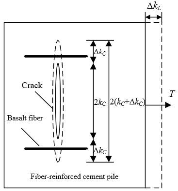
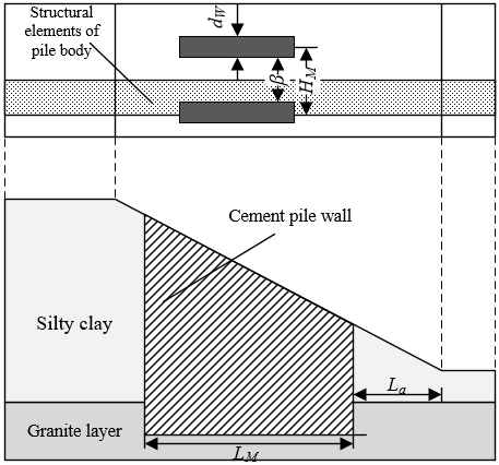
To further explore the influence of basalt fiber-reinforced cement piles on the stability and failure mode of slopes, this paper constructs a slope model as shown in Figure 4. The slope is 20m high with a slope ratio of 1: 2.5. The lower part of the slope is completely weathered granite, and the upper part is a layer of uniform silty clay. Figure 4 also shows the original cement piles used to enhance the slope structure. The numerical simulation of the slope stability with reinforced cement piles can be solved as a three-dimensional problem. During the solving process, the 3D model needs to be converted into a planar model; then, the safety coefficient of the slope needs to be calculated to obtain the stability score of the slope.
Figure 4. Structure of original reinforced cement piles
Based on the limit equilibrium method, this paper calculates the evaluation indices of stability of the established model. The reinforced cement piles were arranged discretely into the slope. Then, an arbitrary section was extracted from the slope, which contains the piles in the same direction along the slope and under the same stress. Let NS be the area replacement rate of the pile body inside the equivalent pile wall; βTC and βZT be the equivalent deformation moduli of the pile body and the silty clay layer, respectively. Then, the equivalent deformation modulus βDX per unit volume of the equivalent entity in the reinforcement area can be calculated by:
${{\beta }_{DX}}=\left( 1-{{N}_{S}} \right){{\beta }_{TC}}+{{N}_{S}}{{\beta }_{ZT}}$ (29)
Let TMTC and TMZT be the equivalent weights of the pile body and the silty clay layer, respectively. Then, the equivalent weight TMDX per unit volume of the equivalent entity in the reinforcement area can be calculated by:
$T{{M}_{DX}}=\left( 1-{{N}_{S}} \right)T{{M}_{TC}}+N_{S}^{{}}T{{M}_{ZT}}$ (30)
Let εTC and εZT be the equivalent cohesions of the pile body and the silty clay layer, respectively. Then, the equivalent cohesion εDX per unit volume of the equivalent entity in the reinforcement area can be calculated by:
${{\varepsilon }_{DX}}=\left( 1-N_{S}^{{}} \right){{\varepsilon }_{TC}}+N_{S}^{{}}{{\varepsilon }_{ZT}}$ (31)
Let ψTC and ψZT be the equivalent internal friction angles of the pile body and the silty clay layer, respectively. Then, the equivalent internal friction angle ψDX per unit volume of the equivalent entity in the reinforcement area can be calculated by:
$tan{{\psi }_{DX}}=\left( 1-N_{S}^{{}} \right)tan{{\psi }_{TC}}+{{N}_{S}}tan{{\psi }_{ZT}}$ (32)
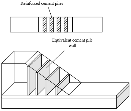
Figure 5. Structure of improved reinforced cement piles
To enhance the safety factor of the slope, the original reinforced cement pile structure was improved by connecting the piles via lap joints into walls of good bending strength and rigidity. The improved structure is shown in Figure 5. Each wall provides the slip mass with a sliding resistance, while the slip mass drags the wall by a sliding force. During the ultimate equilibrium between the two forces, the sliding resistance of the granite layer in the slip mass between walls on the sliding surface μ can be calculated by:
$\begin{align} & {{G}_{SB}}=\int_{0}^{1}{\left[ \beta \left( {{\varepsilon }_{TC}}+{{\Phi }_{{{M}_{S}}}}\tan {{\psi }_{TC}} \right)/{{G}_{TC}} \right]d\mu } \\ & ={{F}_{s}}+{{T}_{S}}\beta -2{{f}_{S}} \\ \end{align}$ (33)
where, FS and TS are the sliding force induced by the dead weight of the slip mass and the landslide thrust of the slip mass, respectively; fS is the friction on the wall-soil interface. The sliding resistance of the wall on the sliding surface μ can be calculated by:
$\begin{align} & {{{\hat{G}}}_{SB}}=\int_{0}^{1}{\left[ \tau \left( {{\varepsilon }_{TC}}+{{\Phi }_{{{M}_{S}}}}\tan {{\psi }_{W}} \right)/{{G}_{TC}} \right]d\mu } \\ & ={{F}_{W}}+{{T}_{S}}\tau -2{{f}_{S}} \\ \end{align}$ (34)
where, FW is the sliding force induced by the dead weight of the wall. Hence, the safety coefficient GSB of the slope is greatly affected by fS, FS, and TS. If the reinforced cement piles have a strong anti-crack effect, the probability of slope damage can be reduced to a certain extent at relatively large FS and TS. Compared with the slope enhanced by ordinary cement piles, the slope enhanced by the improved structure is very unlikely to suffer from instability of inter-wall slip mass after reaching ultimate equilibrium, because the maximum fS is only slightly smaller than the strength of the BFRCBC. In this case, the sliding resistance of the slip mass between the walls can be calculated
$\begin{align} & {{G}_{SB}}=\int_{0}^{1}{\left[ \beta \left( {{\varepsilon }_{TC}}+{{\Phi }_{{{M}_{S}}}}\tan {{\psi }_{TC}} \right)/{{G}_{TC}} \right]d\mu } \\ & ={{F}_{s}}+{{T}_{S}}\beta -2{{f}_{\text{max}}} \\ \end{align}$ (35)
The sliding resistance of the wall can be calculated by:
$\begin{align} & {{{\hat{G}}}_{SB}}=\int_{0}^{1}{\left[ \tau \left( {{\varepsilon }_{TC}}+{{\Phi }_{{{M}_{S}}}}\tan {{\psi }_{W}} \right)/{{G}_{TC}} \right]d\mu } \\ & >{{F}_{W}}+{{T}_{S}}\tau -2{{f}_{\text{max}}} \\ \end{align}$ (36)
Table 1. Compressive strength of BFRCBC with different dosages of fibers
|
|
Dosage |
0 |
0.15 |
0.3 |
0.45 |
0.6 |
|
Simulated value |
Compressive strength |
67.35 |
68.47 |
68.94 |
68.47 |
69.72 |
|
Peak strain |
0.207 |
0.206 |
0.215 |
0.215 |
0.237 |
|
|
Test value |
Compressive strength |
65.8 |
68.9 |
65.7 |
64.2 |
64.5 |
Figure 6. Load-displacement curves of cement piles with different dosages of fibers
Uniaxial compression tests were designed for cement piles to disclose the change law of BFRCBC strength with different dosages of fibers. Figure 6 provides the load-displacement curves of cement piles mixed with 0%, 0.15%, 0.3%, 0.45%, and 0.6% fibers. Table 1 presents the compressive strength of BFRCBC with different fiber dosages. It can be seen that the test compressive strengths of BFRCBC were basically consistent with the simulated values, with a very small error. With the growing fiber dosage, the compressive strength first increased and then declined. In the linear elastic phase, the dosage of basalt fibers had an increasingly small influence on the compressive strength and peak strain of BFRCBC. With the growth in fiber dosage, the basalt fibers gradually exerted its bonding effect, and the BFRCBC was enhanced more and more apparently.
Table 2. Compressive strength of BFRCBC with different fiber lengths
|
|
Length |
0 |
10 |
20 |
30 |
40 |
|
Simulated value |
Compressive strength |
67.36 |
68.95 |
68.75 |
69.13 |
69.27 |
|
Peak strain |
0.207 |
0.207 |
0.216 |
0.216 |
0.216 |
|
|
Test value |
Compressive strength |
65.6 |
68.2 |
65.4 |
64.6 |
64.8 |
Figure 7. Load-displacement curves of cement piles with different fiber lengths
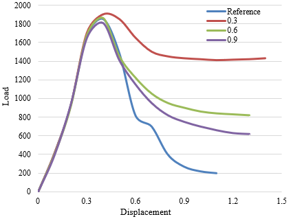
Figure 8. Load-displacement curves of cement piles with different fiber diameters
The length of basalt fiber could also affect the strength development of BFRCBC. Uniaxial compression tests were designed for cement piles to disclose the change law of BFRCBC strength with different fiber lengths. Figure 7 provides the load-displacement curves of cement piles mixed with fibers of different lengths. Table 2 presents the compressive strength of BFRCBC with different fiber lengths. It can be seen that the increase of fiber length could slightly enhance the compressive strength of BFRCBC, and delay the deformation and cracking of cement piles. After the fiber length increased to 40mm, the compressive strength of BFRCBC was 2.56% greater than that of the reference group. However, as a flexible material, the basalt fibers should not be too long. Excessively long basalt fibers hinders the exertion of pile strength.
Similarly, uniaxial compression tests were designed for cement piles to disclose the change law of BFRCBC strength with different fiber diameters: 0.3mm, 0.6mm, and 0.9mm. Figure 8 provides the load-displacement curves of cement piles mixed with fibers of different diameters. Table 3 presents the compressive strength of BFRCBC with different fiber diameters. The compressive strength of BFRCBC decreased with the rise in fiber diameter. The peak strength of cement piles was observed at the fiber diameter of 0.3mm, which is 5.21% greater than that of the control group. Therefore, when the dosage and length of basalt fibers are fixed, properly reducing fiber diameter helps to improve the compressive strength and toughness of the cement piles.
Table 3. Compressive strength of BFRCBC with different fiber diameters
|
|
Diameter |
0 |
0.3 |
0.6 |
0.9 |
1.2 |
|
Simulated value |
Compressive strength |
66.36 |
69.82 |
69.94 |
70.13 |
71.05 |
|
Peak strain |
0.207 |
0.235 |
0.241 |
0.241 |
0.243 |
|
|
Test value |
Compressive strength |
65.7 |
66.2 |
67.1 |
67.2 |
64.5 |
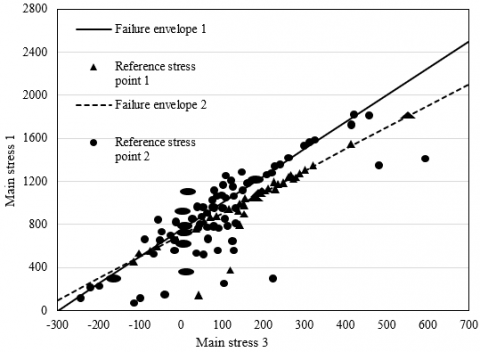
Figure 9. Stress at reference points under original and improved reinforcement structures
To further analyze the enhancement effects of different reinforced cement pile structures on slopes that are instable due to damages, this paper randomly samples the main stresses of Gaussian integral points on the upper part of the cement piles in the independent shear slip band. Figure 9 compares the stress states and failure envelopes of each point before and after the structural improvement. Before the improvement, most stress state points were within the failure envelope; after the improvement, most stress points were on the envelope. Therefore, the cement piles belong to elastic state and failure state before and after the improvement, respectively. In the former case, the shear strength of the piles is not fully exerted. That is, under the same area replacement ratio, the improved structure has a higher slope safety coefficient than the original structure.
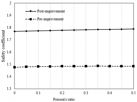
Figure 10 shows how the deformation modulus affects slope stability. As the deformation modulus increased from 0MPa to 1,000MPa, large displacement could be observed at the point of abrupt change on the load-displacement curve of cement piles, but the safety coefficient of the enhanced slope changed very slightly, which could be neglected. Similarly, Figure 11 shows how the Poisson’s ratio affects slope stability. As the Poisson’s ratio increased from 0 to 0.5, the plastic zone of cement piles changed significantly, but the safety coefficient of the enhanced slope was not sensitive to the change of Poisson’s ratio: it basically remained unchanged.
Figure 10. Influence of deformation modulus on slope stability
Figure 11. Influence of Poisson's ratio on slope stability
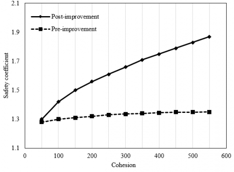
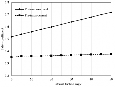
The stability of natural soil slopes is significantly affected by shear strength parameters like cohesion and internal friction angle. The proposed slope model was subject to slope stability analysis, with the aim to obtain the change laws of the safety coefficient of the cement pile-enhanced slope with the variation in shear strength parameters. Figures 12 and 13 record how the cohesion and internal friction angle affect slope stability, respectively. After structural improvement, the safety coefficient of the slope model increased linearly with the growing cohesion. By contrast, the increase of safety coefficient was rather small before the improvement. With the widening of internal friction angle, the safety coefficients of the slope model increased in both original and improved structures. The safety coefficient of the improved structure increased faster than that of the original structure, indicating that the cement piles in the improved structure exerted more anti-shear effect than those in the original structure. The improved strength of BFRCBC clearly amplifies the stability of cement pile-enhanced slope.
Figure 12. Influence of cohesion on slope stability
Figure 13. Influence of internal friction angle on slope stability
This paper carries out a two-fold analysis on the influence of BFRCBC over slope stability. For one thing, the anti-crack mechanism of BFRCBC was analyzed: the strength analysis was carried out by the rule of mixtures, the anti-crack analysis was implemented by the fiber spacing theory, and the entire anti-crack process was discussed in details. For another, uniaxial compression tests were performed on cement piles to obtain the change laws of BFRCBC with different fiber dosages, fiber lengths, and fiber diameters. Through the tests, the authors evaluated how the slope stability is affected by deformation modulus, Poisson’s ratio, cohesion, and internal friction angle. The results show that the slope enhanced by BFRCBC cement piles is very stable.
The work is supported by Ankang Science and Technology Research and Development Program (Grant No.: AK2019SF-09, AK2020-GY03-2), and Scientific Research Fund of Shaanxi Provincial Department of Education (Grant No.: 19JK0012).
[1] Bharati, A.K., Ray, A., Rai, R., Shrivastva, B.K. (2021). A stability classification system for the dragline dump slope. Mining, Metallurgy & Exploration, 38(2): 1095-1109. https://doi.org/10.1007/s42461-021-00409-8
[2] Kainthola, A., Sharma, V., Pandey, V. H. R., Jayal, T., Singh, M., Srivastav, A., Singh, T.N. (2021). Hill slope stability examination along Lower Tons valley, Garhwal Himalayas, India. Geomatics, Natural Hazards and Risk, 12(1): 900-921. https://doi.org/10.1080/19475705.2021.1906758
[3] Hazari, S., Ghosh, S., Sharma, R.P. (2021). A comparative study of soil slope stability under seismic loading condition. In Geohazards, 86: 11-22. https://doi.org/10.1007/978-981-15-6233-4_2
[4] Tschuchnigg, F., Tschuchnigg, H.F., Sallinger, M. (2018). Effect of failure criterion on slope stability analysis. In Numerical Methods in Geotechnical Engineering IX, 1055-1062.
[5] Shen, Z.P., Chen, W.W. (2016). Profile orientation and slope stability analysis. Scientific Programming, 2016: Article ID 7029786 https://doi.org/10.1155/2016/7029786
[6] Zhang, R., Zhao, J., Wang, G. (2016). Stability analysis of anchored soil slope based on finite element limit equilibrium method. Mathematical Problems in Engineering, 2016: 7857490. https://doi.org/10.1155/2016/7857490
[7] Cao, L., Wang, Y., Xu, Y., Tan, Y. (2016). Effect of unsaturated seepage on slope stability under rainfall. Special Topics & Reviews in Porous Media: An International Journal, 7(2): 131-139. https://doi.org/10.1615/SpecialTopicsRevPorousMedia.2016016999
[8] Yang, Z.F., Ding, Y.Q., Chen, J.G. (2021). Stability analysis of rock-soil mixture slope. In IOP Conference Series: Earth and Environmental Science, 638(1): 012099. https://doi.org/10.1088/1755-1315/638/1/012099
[9] Oggero, M., Insana, A., Barla, M. (2021). Climate change effects on slope stability. In International Conference of the International Association for Computer Methods and Advances in Geomechanics, 126: 473-481. https://doi.org/10.1007/978-3-030-64518-2_56
[10] Rusydy, I., Fathani, T.F., Al-Huda, N., Iqbal, K., Jamaluddin, K., Meilianda, E. (2021). Integrated approach in studying rock and soil slope stability in a tropical and active tectonic country. Environmental Earth Sciences, 80(2): 1-20. https://doi.org/10.1007/s12665-020-09357-w
[11] Bharti, J.P., Mishra, P., Sathishkumar, V.E., Cho, Y., Samui, P. (2021). Slope stability analysis using Rf, Gbm, Cart, Bt and Xgboost. Geotechnical and Geological Engineering, 39(5): 3741-3752. https://doi.org/10.1007/s10706-021-01721-2
[12] Fattahi, H., Ilghani, N.Z. (2020). Slope stability analysis using Bayesian Markov chain Monte Carlo method. Geotechnical and Geological Engineering, 38(3): 2609-2618. https://doi.org/10.1007/s10706-019-01172-w
[13] Wang, S., Mei, G., Xie, X., Yaoxuan, L., Yao, L. (2020). Slope stability analysis under rainfall conditions considering unsaturated characteristics of materials. In E3S Web of Conferences, 165: 03030. https://doi.org/10.1051/e3sconf/202016503030
[14] Yun, L., Jie, L. (2016). Dynamic stability analysis of rock slope supported by double-row piles based on Hoek-Brown criterion. Electronic Journal of Geotechnical Engineering, 21(17): 5859-5869.
[15] Dassanayake, A.B.N., Phien-Wej, N., Giao, P.H. (2016). Groundwater flow modeling and slope stability analysis for deepening of Mae Moh open pit lignite min. Geotechnical Engineering Journal of the SEAGS and AGSSEA, 47(3): 101-115.
[16] Chen, H., Long, X., Huang, X., Zou, Z., Yan, Q. (2016). Effect of slope shape on side slope stability under seismic action. Electronic Journal of Geotechnical Engineering, 21: 12.
[17] Cundall, P.A., Damjanac, B. (2016). Considerations on slope stability in a jointed rock mass. In 50th US Rock Mechanics/Geomechanics Symposium. American Rock Mechanics Association. ARMA-2016-339.
[18] Acharya, K.P., Bhandary, N.P., Dahal, R.K., Yatabe, R. (2016). Seepage and slope stability modelling of rainfall-induced slope failures in topographic hollows. Geomatics, Natural Hazards and Risk, 7(2): 721-746. https://doi.org/10.1080/19475705.2014.954150
[19] Tiedeu, W.N., Jiang, D., Chen, J., Fan, J. (2020). A review on rock slope stability: Failure mechanisms. Stabilization Techniques and Implications for Mining Engineering, 51(4): 169-180.
[20] Kamchoom, V., Leung, A.K. (2018). Hydro-mechanical reinforcements of live poles to slope stability. Soils and Foundations, 58(6): 1423-1434. https://doi.org/10.1016/j.sandf.2018.08.003
[21] Munro, M.C., Mohajerani, A. (2018). Slope stability evaluation of iron ore fines during marine transport in bulk carriers. Canadian Geotechnical Journal, 55(2): 258-278. https://doi.org/10.1139/cgj-2016-0468
[22] De Vita, P., Fusco, F., Tufano, R., Cusano, D. (2018). Seasonal and event-based hydrological and slope stability modeling of pyroclastic fall deposits covering slopes in Campania (Southern Italy). Water, 10(9): 1140. https://doi.org/10.3390/w10091140
[23] Ramer, D.S., Imholte, T.J., Wang, M.C. (2000). Stability of talus slope at lewistown narrows. In ISRM International Symposium. International Society for Rock Mechanics and Rock Engineering. ISRM-IS-2000-426.
[24] Chang, J., Song, S., Feng, H. (2016). Analysis of loess slope stability considering cracking and shear failures. Journal of Failure Analysis and Prevention, 16(6): 982-989. https://doi.org/10.1007/s11668-016-0174-2
[25] Pang, H., Nie, X., Sun, Z., Hou, C., Dias, D., Wei, B. (2020). Upper bound analysis of 3D-reinforced slope stability subjected to pore-water pressure. International Journal of Geomechanics, 20(4): 06020002. https://doi.org/10.1061/(ASCE)GM.1943-5622.0001636