Siva Sankara Rao Yemineni* | Mallikarjuna Rao Kutchibotla
OPEN ACCESS
Shells are constructed for the most part missiles, submarines, tanks and fluid reservoirs. Shells are susceptible to buckling failure under external pressure. During design process buckling analysis is the important parameter. Therefore engineering designers have to well understand the shell buckling to prevent the unexpected failure of structures well before the yield strength of the material. In the present investigation, comparison of the linear buckling strengths of unstiffened carbon fibre reinforced polymer (CFRP) composite conical shelland the linear and nonlinear buckling strengths of Al-Cu alloy under the action of uniform external pressure using both theoretical and finite element analysis (ANSYS 12.0) is done and corresponding conclusions are presented.
unstiffened conical shell, uniform external pressure, linear buckling analysis, non-linear buckling analysis, Al-Cu alloy, CFRP composite
Shells are those structural elements which possess higher radius-to-thickness ratio i.e. greater than 10. There are cylindrical, conical, spherical shells with and without stiffeners made up of metal alloys and composite materials used as structural elements. Most of these shells especially conical shells find applications in aeronautical, marine structures and also used in the construction of pressure vessels, pipelines, offshore platforms, etc. Usually conical shell structures load bearing capacity is limited by either elastic, elastic-plastic or plastic buckling depending upon the radius-to-thickness ratio. In practice, shells are subjected to various loading conditions such as external pressure, internal pressure, axial compression, bending, torsion, etc., or combined loading. Instability or failure of these structural elements occurs when loaded beyond their buckling load. As a result, stability behavior needs to be considered in their design analysis.
Buckling is the failure of a structure subjected to compressive load when it is undergone large transverse displacements and is a critical phenomenon in the structural failure analysis. If an element is susceptible to buckling then its design must have to consider both the material and buckling strengths. Also buckling strength of shell structures depends on several things like type of support, linearity, type of material used, type of loading like structural or thermal and geometric imperfections etc. In the analysis considering all these parameters is difficult. So, some parameters are considered in the current investigation. Empirical formulae are available for linear buckling and not available for nonlinear buckling. So nonlinear buckling analysis can be done by using advanced computers installed with finite element software (ANSYS 12.0).
Finite element analysis on several thin walled-shell structures of cylindrical and elliptical cross sections using ANSYS and LS-DYNA was carried out by T. Subramani, Athulya Sugathan [1]. In this, only cylindrical and elliptical cross sections are considered for linear and nonlinear buckling analysis. Conical shell structures comprise light weight with high strength in different industrial applications with the significance of extensive use in tanks and silos [2], offshore structures, aeronautical and aerospace technology, ship and submarine hulls [3], pipelines and industrial chemical plants [4-5].
The first-order shear-deformation theory (also known as Mindlin-Reissner shell theory) is used to govern the accurate modeling of composite shells. Some experiments on buckling of conical shells exposed to external pressure were executed out by Tokugawa in 1932. Some other experiments on cones for external pressure application were done by Jordan, Shroeder E. and Kusterer.
Shroeder, Kusterer, Singer, Eckstein, Ben-David [5-7] conducted a series of experiments on cones under the influence of external pressure, the elastic instability of aluminum cones with different cone angles was examined. Experiments on failure of three aluminum conical shells in plastic buckling range under external pressure are conducted by Ross et al. [8].
A review of experimental testing techniques for applying external hydrostatic pressure to buckling of shells is mentioned by MacKay, van Keulen [9]. The buckling strength of orthotropic composite and layered sandwich conical shells exposed to several loading conditions was analyzed by Sofiyev, Schnack, Bert, Crisman [10-14], Bert et al., Tong [15-16]. Bert, Crisman, Nordby, Tong presented thorough experimental study on the buckling strength of cylindrical and conical sandwich shells made from the materials such as glass/epoxy fiber facings and aluminum alloys honeycomb cores. The specimens dimensions were: 1.12m diameter cylinder and truncated cone with a large diameter of 1.47m. Mahdi, Hamouda, Sahari, Khalid conducted experimentsfor investigating the buckling strength of carbon fiber reinforced plastics (CFRP) and glass fiber reinforced plastic (GFRP) filament wound conical shells for the application of axial compression.
The specimens dimensions were defined their experiments as 328 mm diameter at the big end, with r_2/t ranging from 75 to 162mm. The equipment used for fabrication of cones includehorizontal helical filament winding machine and a stainless steel mandrel [17]. Similarly, Golzana, Showkatib observed the effect of cylindrical part length on the crushing strength of cone cylinder cone intersection in composite shells. The part length of cylindrical portion is varied between 0 and 50 mm.
The wet filament-winding process is used to fabricate Glass/epoxy and carbon/epoxy filament-wound laminated cones. The specimens had two diameters equal to 98.2 mm and 112.8 mm at the big end of the cone [18]. The present investigation covers the buckling behavior of conical shells made up of materials Al-Cu alloy (Al 243455-IS CON-T6), carbon fibre reinforced plastic (CFRP) using ANSYS 12.0 and empirical relations and their comparison for the validation of the obtained results.
Theoretical determination of Strength of Conical Shell for Buckling due to Uniform External Pressure
3.1 Assumptions considered for the conical shell analysis [1]
The following are the assumptions considered for the conical shell analysis:
(1). THE MEMBER IS INITIALLY PERFECTLY STRAIGHT.
(2). THE MATERIAL IS ELASTO-PLASTIC WITH STRAIN HARDENING PROPERTY.
(3). THE SELF-WEIGHT OF THE STRUCTURE NEED NOT CONSIDERED.
(4). THE MEMBER WILL BE FAILED BY BUCKLING ALONE.
(5). Imperfections of the member can be considered.
3.2 Materials considered for the conical shell and its properties
Table 1. Properties of Al-Cu alloy
|
S. No. |
Description of Property |
Value of property |
|
|
Tensile strength |
435 MPa |
|
|
Yield strength |
385 MPa |
|
|
Elongation |
6 % |
|
|
Young’s modulus |
70, 000 MPa |
|
|
Tangent modulus |
700 MPa (say) |
|
|
Poisson’s ratio |
0.324 |
|
|
Density |
2, 700 kg/ m3 |
3.3 Determination of critical buckling pressure (Pc)
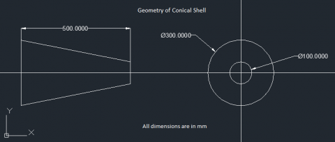
In this section determination of critical buckling stress (Pc) for the conical shell which is under the action of uniform external hydrostatic pressure is carried out by theoretical relations and ANSYS12.0. The geometry of the conical shell considered in this problem is shown in Figure 1. Here the dimensions are in millimetres.
Figure 1. Geometry of conical shell
3.4 The critical buckling pressure [19]
Pc=0.855(1−ϑ2)0.75EhL(hrm)1.5(cosα)1.5 (1)
where,
ϑ =Poison’s ratio=0.324,
E=Young’s Modulus=70, 000 MPa,
L =Length of the conical shell=500 mm,
h =Thickness of the conical shell=6mm (say),
rm= Mean radius of the conical shell r1+r22=50+1502=100mm
α =Half cone angle=Tan-1(100/500) =11.310
On solving the equation (1) the obtained critical buckling pressure, Pc =11.26 N/mm2.
3.5 According to finite element analysis
[20] For the given thickness, length and inner diameter of the conical shell, Buckling Load Factor (BLF) is obtained from Eigen buckling analysis of the shell using ANSYS 12.0 in terms of the frequency of the shell which is also called as Eigen value. Hence we can calculate the critical buckling pressure (Pc) from BLF.
3.5.1 Shell element considered for FEA in ANSYS 12.0 [20]
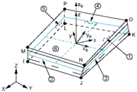
SOLSH190 as shown in figure 2 is suitable for the simulation of shell structures with a huge range of thickness (from thin to moderate thick). The element consists of the continuum solid element topology and features eight-node connectivity with three degrees of freedom all the nodes as translations in the nodal x, y, and z directions. Alsothe option like degenerate prism is available, but should only be suitable as filler elements during mesh generation. This element have the properties like plasticity, hyper elasticity, stress stiffening, creep, large deflection, and large strain. And also has the capability of mixed u-P formulation for the simulation of deformations of almost incompressible elastoplastic materials, and fully incompressible hyper elastic materials. The element mathematical formulation is depend on logarithmic strain and true stress measures. SOLSH190 is also suitable for the modeling of laminated shells and sandwich structure construction.
Figure 2. Shell190 geometry
3.5.2 Modelling of shell
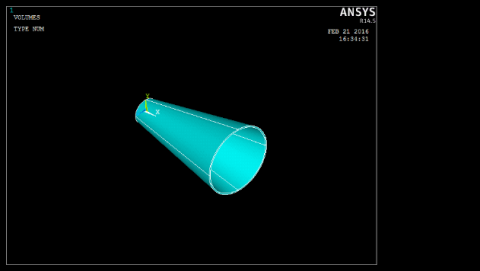
For the analysis purpose in ANSYS 12.0 the unsupported length of the conical shell is modeled which is as shown in Figure 3.
Figure 3. Modelling of conical shell in ANSYS 12.0
3.5.3 Application of boundary conditions to modelled conical shell
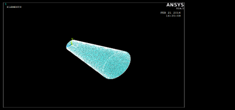
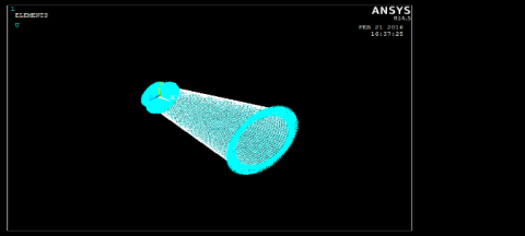
Figure 4. Meshing of conical shell
Figure 5. Application of displacement boundary conditions
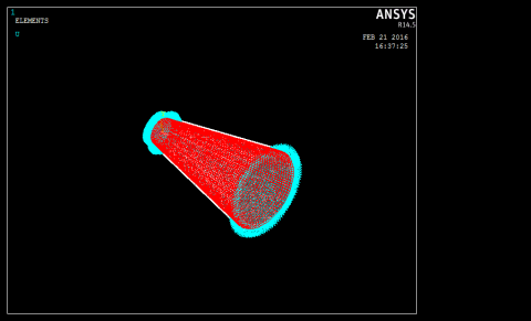
Figure 6. Application of uniform external pressure of 6 MPa
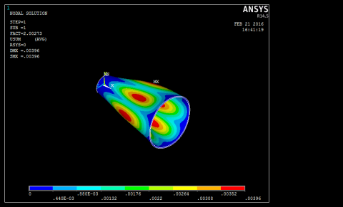
Figure 7. Buckled mode for linear buckling analysis of al-cu alloy conical shell
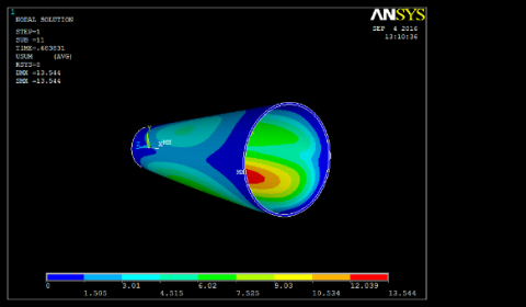
Figure 8. Buckled mode for non linear buckling analysis of al-cu alloy conical shell
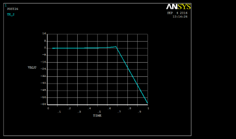
Figure 9. Displacement vs time graph for non linear buckling analysis of al-cu alloy conical shell
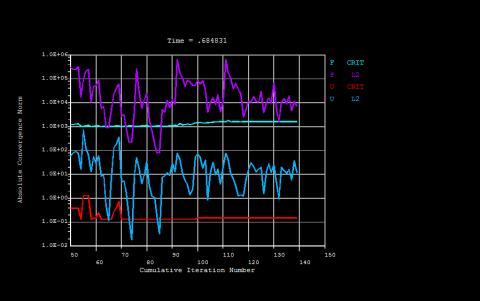
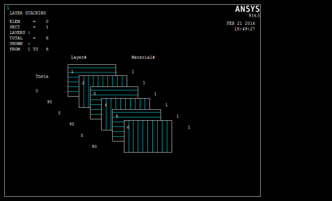
Figure 4 shows the meshing of conical shell geometry in ANSYS 12.0, and figures Figure 5, Figure 6, respectively show the application of displacement boundary conditions and uniform external hydrostatic pressure at each node on the circumferences of the left and right ends of the shell are constrained as UX=UY=UZ =0 and ROTX=ROTY=ROTZ=0 as the consideration of fixed support at the both ends of the modelled conical shell. The value of uniform external hydrostatic pressure of 6 MPa as let us say the shell is at a depth of 600 metres. Figure 7, Figure 8 respectivelyshow the buckled modes for linear and nonlinear buckling analysis of Al-Cu alloy conical shell. Figure 9, Figure 10 respectively show the Displacement vs Time Graph and the Convergence vs Iteration number graph for nonlinear buckling analysis of Al-Cu Alloy conical shell. Figure 11, Figure 12, respectively show the orientation of fibers, buckled mode for linear buckling analysis of CFRP composite conical shell.
Figure 10. Convergence vs iteration number graph for non linear buckling analysis of al-cu alloy conical shell
Table 2. Mechanical & physical properties of cfrp composite [26]
|
S.No. |
Description of Property |
Value |
|
1 |
Ex |
175,000MPa |
|
2 |
Ey |
7,000MPa |
|
3 |
Ez |
7,000MPa |
|
4 |
vxx |
0.25 |
|
5 |
vyz |
0.01 |
|
6 |
vzx |
0.25 |
|
7 |
GXY |
3,500 MPa |
|
8 |
GYZ |
1,400 MPa |
|
9 |
GZX |
3,500 MPa |
|
10 |
Density |
1,550 kg/m2 |
Figure 11. Orientation of fibers in cross ply CFRP composite conical shell
Figure 12. Buckled mode for linear buckling analysis of cfrp composite conical shell
Table 3. Comparison of buckling of al-cu alloy and CFRP conical shells
|
S.No. |
Parameter |
Linear Bucking Analysis |
Non-linear Buckling Analysis |
|||
|
Al-Cu alloy |
Percentage Deviation (%) |
Composite (CFRP) |
Al-Cu alloy |
|||
|
Theoretical |
FEA |
FEA |
FEA |
|||
|
1. |
Bucking load Factor |
- |
2.00 |
- |
2.21 |
0.68 |
|
2. |
External Pressure applied (N/mm2 ) |
6 |
6 |
- |
6 |
6 |
|
3. |
Bucking stress (N/mm2 ) |
11.26 |
12.0 |
3.45 % |
13.26 |
4.1 |
As per the results shown in the above Table 3,
(1). The buckling stress value obtained for the linear buckling strength of Al-Cu alloy conical shell using FEA is more than that obtained using theoretical approach, the results are deviated by 3. 45 %.
(2). The linear buckling analysis of composite CFRP conical shell in ANSYS-12.0 gave the higher value for buckling stress than that for the linear buckling analysis of Al-Cu alloy conical shell using theoretical and FEA in ANSYS-12.0. Hence, using the CFRP composite material for the conical shell will give higher value for its buckling strength than that using Al-Cu alloy.
(3). However, the nonlinear buckling analysis of Al-Cu alloy conical shell considering both geometric and material non-linearity gives accurate results than the linear buckling analysis and the value obtained for buckling pressure using nonlinear buckling analysis in ANSYS-12.0 is far less than those obtained using linear FEA in ANSYS-12.0 and theoretical solutions.
(1) For Al-Cu alloy conical shell, critical buckling strength obtained from theoretical formula is validated using FEA (Eigen buckling analysis, ANSYS-12.0). FEA overestimated the buckling stress value for Al-Cu alloy conical shell than that of theoretical analysis.
(2) Also, for Al-Cu alloy conical shell, the critical buckling strengths obtained for Non-linear and linear buckling analysis using ANSYS 12.0 are compared against each other. Here, in this comparison, non-linear buckling analysis estimated lesser value than linear buckling analysis for critical buckling strength and is closer to actual failure of the conical shell. Hence nonlinear analysis is preferred to linear analysis for buckling process which is almost closer to the real time buckling process.
(3) For the CFRP composite shell, critical buckling strength obtained using linear buckling analysis is more than that obtained for Al-Cu alloy. Hence, we can replace Al-Cu alloy by CFRP composite material for the conical shell that is susceptible to buckling under uniform external pressure.
[1] Subramani, T., Sugathan, A. (2014). Finite Element Analysis of thin walled-shell structures by ANSYS and LS-DYNA. International Journal of Modern Engineering Research (IJMER), 2(4):1576-1587.
[2] Tokugawa, T. (1932). Experiments on the elastic stability of a thin-wall cone under uniform normal pressure on all sides, and an approximate method for computing its collapsible pressure. In Congress of Applied Mechanics League, Zõsen Kyõkai (Shipbuilding Association), Miscellaneous Publications, 125: 151-169.
[3] Golzan, B.S., Showkati, H. (1955). Buckling of thin conical shells under uniform external pressure. Thin-Walled Structures, 46(5): 516-529. https://doi.org/10.1016/j.tws.2007.10.011
[4] Shroeder, F.J., Kusterer, E.T. (1963). An experimental determination of the stability of conical shells. Journal of Applied Mechanics, 30(1). https://doi.org/10.1115/1.3630066
[5] Singer, J., Eckstein, A. (1962). Experimental investigations of the instability of conical shells under external pressure. Bull. Res. Counc. of Israel, 11C: 97-122.
[6] Singer, J. (1968). Experimental investigation of buckling of electroformed conical shells under hydrostatic pressure. AIAA Journal, 6(12): 2332-2338. https://doi.org/10.2514/3.4991
[7] Sendelbeck, R.L., Singer, J. (1970). Further experimental studies of buckling of electroformed conical shells. AIAA Journal, 8(8): 1532-1534. https://doi.org/10.2514/3.49845
[8] Ross, C.T.F., Sawkins, D., Johns, T. (1999). Inelastic buckling of thick walled circular conical shells under external hydrostatic pressure. Ocean Engineering, 26(12): 1297-1310. https://doi.org/10.1016/S0029-8018(98)00066-3
[9] MacKay, J.R., Van Keulen, F. (2010). A review of external pressure testing techniques for shells including a novel volume-control method. Experimental Mechanics, 50(6): 753-772. https://doi.org/10.1007/s11340-009-9272-3
[10] Tong, L. (1994). Buckling load of composite conical shells under axial compression. Journal of Applied Mechanics, 61(3): 718719. https://doi.org/10.1115/1.2901521
[11] Sofiyev, A.H., Schnack, E. (2003). The buckling of cross-ply laminated non-homogenous orthotropic composite conical thin shell under a dynamic external pressure. ACTA Mechanica, 162(1-4): 2940.
[12] Sofiyev, A.H., Schnack, E. (2003). The buckling of an orthotropic composite truncated conical shell with continuously varying thickness subject to a time dependent external pressure. Composite Part B: Engineering, 34(3): 227-233. https://doi.org/10.1007/s00707-002-1001-2
[13] Sofiyev, A.H. (2010). The buckling of FGM truncated conical shells subjected to combined axial tension and hydrostatic pressure. Composite Structures, 92(2): 488-498. https://doi.org/10.1016/j.compstruct.2009.08.033
[14] Zielnica, J. (2003). Non-linear stability of elastic-plastic conical shell under combined load. Journal of Theoretical and Applied Mechanics, 41(3): 693-709.
[15] Bert, C.W., Crisman, W.C., Nordby, G.M. (1968). Fabrication and fullscale structural evaluation of glass-fabric reinforced plastic shells. Journal of Aircraft, 5(1): 1968, 27-34. https://doi.org/10.2514/3.43903
[16] Bert, C.W., Crisman, W.C., Nordby, G.M. (1969). Buckling of cylindrical and conical sandwish shells with orthotropic facings. AIAA Journal, 7(2): 250-257. https://doi.org/10.2514/3.5082
[17] Tong, L. (1999). Buckling of filament-wound laminated conical shells under axial compression. AIAA Journals, 37(6): 778-781. https://doi.org/10.2514/2.792
[18] Mahdi, E., Hamouda, A.M., Sahari, B.B., Khalid, Y.A. (2002). Crushing behavior of cone-cylinder-cone composite system. Mechanics of Advanced Materials and Structures, 9(2): 99-117. https://doi.org/10.1080/153764902753510499
[19] Ventsel, E., Krauthammer, T. (2001). Theory, analysis, and applications. Thin plates and Shells, 24(8): 688. https://doi.org/10.1201/9780203908723
[20] ANSYS User Manual 12.0.