
Fattah Maulana* | Kristian Felix Fernandes Purba | Amelia Chandra Pratiwi | Rando Tungga Dewa | Anang Setiawan | Kayode James Olaleye | Muhammad Syaiful Fadly
© 2026 The authors. This article is published by IIETA and is licensed under the CC BY 4.0 license (http://creativecommons.org/licenses/by/4.0/).
OPEN ACCESS
This study investigates the ballistic response of spaced Hardox 400 steel armor plates subjected to a 7.62 × 51 mm projectile impact using an explicit dynamic finite element method (FEM) simulation in ANSYS. The investigated system consists of two Hardox 400 steel plates separated by an air gap, with three configurations using plate thicknesses of 3 mm, 4 mm, and 5 mm; in each configuration, the inter-plate spacing is set equal to the plate thickness. The numerical analysis focuses on von Mises stress distribution, deformation, penetration response, and projectile velocity. The maximum von Mises stresses in the front plate are 1320.8 MPa, 1260.2 MPa, and 1176.8 MPa for Models A, B, and C, respectively, while the corresponding rear-plate values are 1259.3 MPa, 966.5 MPa, and 986.5 MPa. The rear-plate deformation and penetration responses also differ among the investigated configurations: Model A shows approximately 8 mm of deformation without complete perforation, while the reported penetration depth decreases to approximately 2 mm in Model B and 0.9 mm in Model C. The projectile velocity-time response confirms substantial deceleration following impact, although the residual-velocity trend should be interpreted together with the deformation and penetration results. Overall, the numerical findings demonstrate that plate thickness and spacing configuration influence the ballistic response of the two-plate Hardox 400 system. Further experimental validation, mesh-sensitivity assessment, and system-level investigations are required before the configuration can be considered for practical protective applications.
plate layered design, numerical simulation, finite element method, anti-ballistic, conflict zone
Ballistic protection remains an important engineering requirement for military, law-enforcement, infrastructure, and other high-risk applications. The development of protective systems requires an understanding of material response, projectile-target interaction, and failure mechanisms under high-velocity impact. Numerical simulation has become an important tool for investigating these phenomena and complementing experimental ballistic testing [1, 2]. Protective structures and armor systems are designed to reduce projectile penetration and limit local damage under ballistic loading. Their performance depends on the mechanical properties of the target material, plate geometry, boundary conditions, projectile characteristics, and the interaction between successive protective elements [3-5]. At the present stage, however, the numerical model in this study represents a plate-level ballistic configuration rather than a complete building, wall, connection, or full-scale protective panel.
Among metallic protection concepts, spaced armor uses two or more plates separated by a defined gap. The front plate interacts first with the incoming projectile, while the rear plate provides additional resistance after the projectile has crossed or perforated the front plate. The ballistic response can therefore be influenced by plate thickness, spacing, material properties, and the sequence of projectile interaction with the plates [6-8].
The investigated configuration consists solely of two Hardox 400 steel plates separated by an air gap and is therefore described throughout this manuscript as a spaced armor configuration. The present model evaluates the sequential response of two separated metallic plates made of the same steel grade, without introducing dissimilar protective layers such as ceramics, Kevlar, polymers, or shear-thickening fluids.
Previous studies have investigated monolithic, multilayered, composite, and spaced metallic armour systems under ballistic impact [6-12]. However, the response of separated Hardox plates remains sensitive to plate thickness, inter-plate spacing, material constitutive behavior, and contact conditions. These parameters can be examined efficiently using explicit dynamic FEM before further experimental validation.
This study therefore develops and analyzes an explicit dynamic FEM model of a two-plate spaced Hardox 400 armor configuration subjected to a 7.62 × 51 mm projectile impact. Three configurations are evaluated using 3 mm, 4 mm, and 5 mm Hardox 400 plates, with the air gap in each configuration set equal to the corresponding plate thickness. The objectives are to compare (i) deformation and penetration response, (ii) von Mises stress distribution in the front and rear plates, and (iii) projectile velocity response during the impact event.
The results are intended to provide plate-level numerical insight into the ballistic response of spaced Hardox 400 armor. Potential future applications may include protective structural components or vehicle armor; however, such applications require additional experimental validation and system-level studies involving full-scale panels, supports, connections, realistic boundary conditions, areal density, and other application-specific design requirements.
2.1 3D modeling and numerical simulation
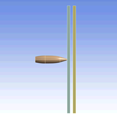
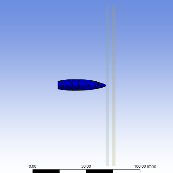
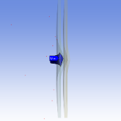
The numerical models of the Hardox 400 plates and the 7.62 × 51 mm projectiles were created in a three-dimensional computer-aided design (CAD) environment according to the specified test dimensions (see Figures 1 and 2). The individual components were then assembled to form the complete specimen for simulation. All relevant geometric and material data were imported into a finite element method (FEM) software package, and the explicit dynamic solver was employed to analyze the projectile impact on the bullet-resistant plate.
Within the explicit dynamic module, the material behavior is defined using the Johnson-Cook constitutive model to represent the high-strain-rate response during impact. The three-dimensional projectile and plate models are assembled according to the simulated geometry, after which material properties, contact definitions, boundary conditions, mesh size, initial projectile velocity, and analysis time are specified for the ballistic impact simulation.
Figure 1. Plate design in 3D software
Figure 2. Example of the spaced Hardox 400 plate arrangement with a 4 mm air gap
Figure 3. Simulation setup
The plate assemblies simulated comprised configurations with plate thicknesses of 3 mm, 4 mm, and 5 mm. For each configuration, the spacing between adjacent plates was set equal to the plate thickness (for example, 4 mm-thick plates separated by a 4 mm gap). Ballistic impacts were modelled using 7.62 × 51 mm projectiles. The complete simulation setup is illustrated in Figure 3.
The numerical simulation is used to evaluate the transient response of the spaced Hardox 400 plates under projectile impact. The reported outputs include plate deformation, von Mises stress distribution, penetration response, and projectile velocity. These outputs are interpreted as plate-level numerical indicators and are not treated as validation of full-scale wall, building, or vehicle armor performance.
2.2 Simulation settings
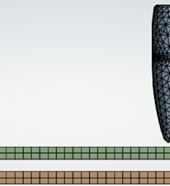
The selection of boundary conditions in ballistic simulations depends on the type of analysis being conducted. For projectile impact simulations, these conditions generally involve defining the material properties of both the projectile and the target, along with the projectile’s initial specifications. In contrast, particle transport problems in fluids or solids typically require boundary conditions applied at the computational domain’s edges, such as periodic boundaries or wall constraints. Accurate specification of boundary conditions is essential to ensure the physical realism of the simulation and to minimize numerical artifacts, such as wave reflections or non-physical interactions at domain boundaries. An illustration of the applied boundary conditions in this study is presented in Figure 4.
In this research, the Johnson-Cook constitutive model is employed to describe the mechanical behavior of the projectile materials (brass and steel) as well as the Hardox 400 target plate [13]. The projectile is assigned an initial velocity of 850 m/s, in accordance with standard ballistic testing protocols for protective materials [14]. Rigid boundary conditions were simulated by constraining all edges of the target plate with fixed supports [15]. A uniform linear mesh with an element size of 1 mm is applied to all model components to ensure consistent discretization. The total simulation time is set to 0.03 s, which is sufficient to capture the complete penetration process of the projectile through the target plate [16].
Figure 4. Boundary condition and mesh modeling
2.3 Johnson-Cook method
This simulation employs the Johnson-Cook (JC) model, a widely used constitutive model that characterizes material behavior under extreme conditions involving high strain, high strain rate, and elevated temperature. In the present study, each material is defined by its corresponding Johnson-Cook parameters, including the individual layers of the 7.62 × 51 mm projectile (brass and steel) as well as the target plate material (Hardox 400). The isotropic elastic properties and the Johnson-Cook material constants for all components are summarized in Tables 1–4.
Table 1. Isotropic elasticity of 7.62 × 51 mm projectile part
|
Property |
Steel (Core) |
Lead (Tip) |
Brass (Jacket) |
|
Density (kg/m3) |
7850 |
10660 |
8520 |
|
Young's modulus (MPa) |
210000 |
1000 |
115000 |
|
Poisson's ratio |
0.33 |
0.42 |
0.31 |
|
Bulk modulus (Pa) |
2.058 × 10¹¹ |
2.083 × 10⁹ |
1.008 × 10¹¹ |
|
Shear modulus (Pa) |
7.894 × 10¹⁰ |
3.521 × 10⁸ |
4.389 × 10¹⁰ |
|
Specific heat capacity (J/KgK) |
452 |
124 |
385 |
Table 2. Johnson-Cook strength of 7.62 × 51 mm projectile parts
|
Parameter |
Steel (Core) |
Lead (Tip) |
Brass (Jacket) |
|
A (MPa) |
1200 |
24 |
206 |
|
B (MPa) |
5000 |
300 |
505 |
|
n |
1 |
1 |
0.42 |
|
C |
0 |
0.1 |
0.01 |
|
$\varepsilon^*$ (1/s) |
0.0005 |
0.0005 |
0.005 |
|
m |
1 |
1 |
1.68 |
|
$T_m$ |
1800 |
760 |
1189 |
Table 3. Isotropic elasticity of Hardox 400
| Parameter | Value |
|
Density (kg/m3) |
7850 |
|
Young's modulus (MPa) |
210000 |
|
Poisson's ratio |
0.33 |
|
Bulk modulus (Pa) |
1.75 1011 |
|
Shear modulus (Pa) |
8.0761010 |
|
Specific heat capacity (J/KgK) |
452 |
Table 4. Johnson-Cook strength of Hardox 400
| Parameter | Value |
|
A (MPa) |
1350 |
|
B (MPa) |
362 |
|
N |
1 |
|
C |
0.0108 |
|
$\varepsilon^*$ (1/s) |
0.0005 |
|
m |
1 |
|
$T_m$ |
1500 |
2.4 Spaced armor configuration
In this study, spaced armor is defined as two Hardox 400 steel plates separated by an air gap. The projectile first interacts with the front plate and subsequently with the rear plate, allowing the response of each plate to be evaluated separately. Numerical simulations are performed for three configurations using 3 mm, 4 mm, and 5 mm Hardox 400 plates. For each configuration, the spacing between the front and rear plates is set equal to the plate thickness. Thus, the investigated cases represent 3 mm plates with a 3 mm gap, 4 mm plates with a 4 mm gap, and 5 mm plates with a 5 mm gap. The configurations are illustrated in Figure 5.
Figure 5. Spaced Hardox 400 armor configurations
3.1 Plastic deformation
Significant plastic deformation is observed around the projectile impact region, as illustrated in Figure 6. In all three configurations, the projectile perforates the front Hardox 400 plate, producing localized deformation and damage in the contact region. Because the penetration extends through the front plate for the investigated 3–5 mm thicknesses, the front plate alone does not arrest the 7.62 × 51 mm projectile under the simulated conditions.
The deformation field in Figure 6 extends beyond the projectile contact diameter, indicating that the local impact response is distributed over a wider region of the front plate. The deformation patterns in Figures 7(A–C) show that the rear Hardox 400 plate provides additional resistance after the projectile has passed through the front plate. The response of the rear plate therefore provides an important measure of the performance of the two-plate spaced armor configuration.
Figure 6. Total deformation of 1st layer: (A) 3 mm Hardox 400, (B) 4 mm Hardox 400, (C) 5 mm Hardox 400
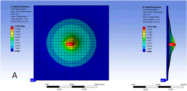
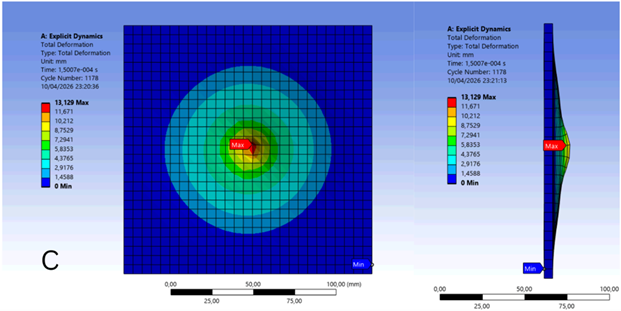
Figure 7. Total deformation of the 2nd layer: (A) Hardox 400 3 mm, (B) Hardox 400 4 mm, (C) Hardox 400 5 mm
As illustrated in Figure 7(A), Model A exhibits approximately 8 mm of rear-plate deformation without complete perforation. In Figure 7(B), the reported penetration depth is approximately 2 mm, while in Figure 7(C) it decreases to approximately 0.9 mm. These results show that the rear-plate deformation and penetration response vary substantially with the investigated plate thickness and spacing configurations. The smaller reported penetration depth in Model C indicates improved resistance to local penetration in this metric; however, direct energy absorption should be quantified from energy-history outputs rather than inferred solely from deformation or stress contours.
3.2 von Mises stress distribution
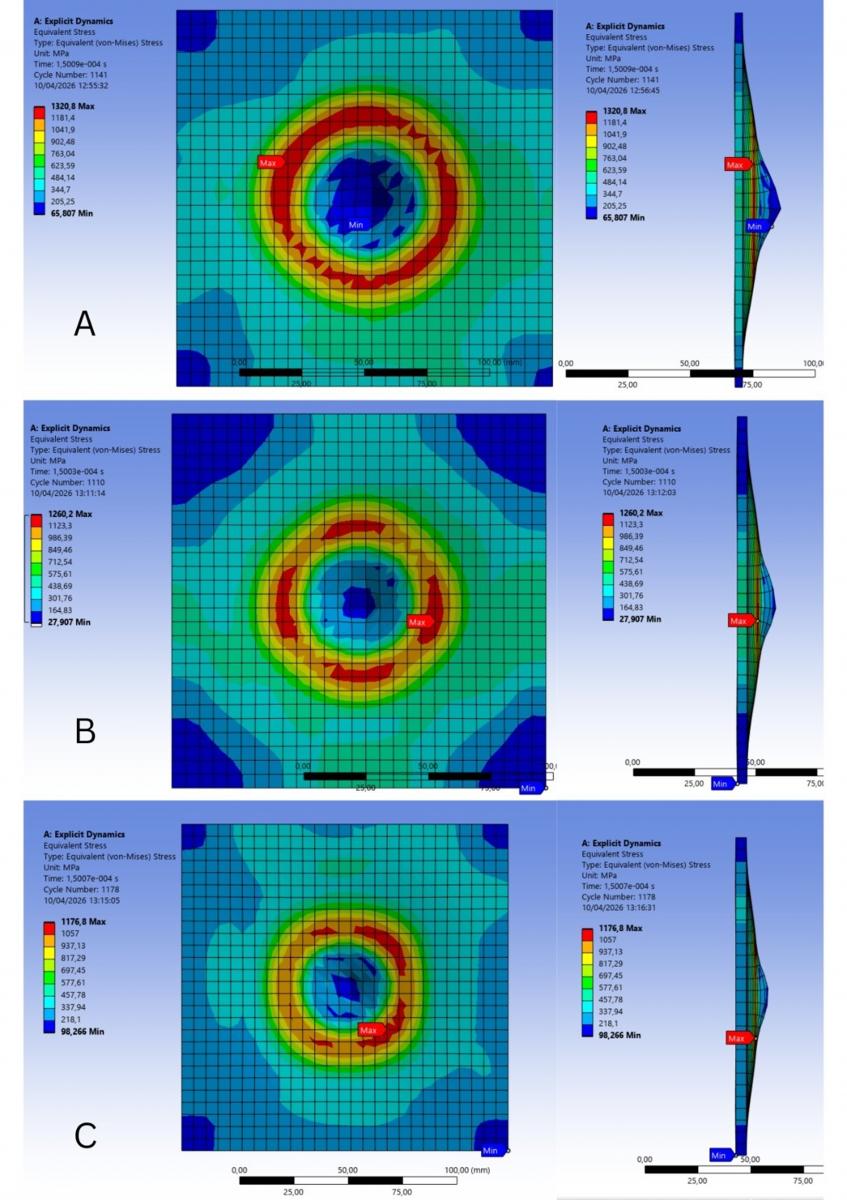
The von Mises stress criterion is employed to evaluate the onset of yielding in a material subjected to multiaxial stress conditions. It is derived from the Distortion Energy Theory, which posits that plastic deformation begins when the material’s distortion energy reaches a critical threshold. The simulation results presented in Figure 8 illustrate the von Mises stress distribution on the first Hardox 400 plate during and after projectile impact.
Figure 8. Equivalent (von Mises) Stress 1st layer: (A) Hardox 400 3 mm, (B) Hardox 400 4 mm, (C) Hardox 400 5 mm
As illustrated in Figure 8, the maximum von Mises stress is concentrated around the projectile impact region. The maximum values are approximately 1320.8 MPa for Model A, 1260.2 MPa for Model B, and 1176.8 MPa for Model C. The stress contours show radial propagation away from the impact region, while the highest values remain localized near the projectile-plate interaction zone.
The deformation profiles shown on the right side of Figure 8 indicate that deformation is primarily localized around the impact area, whereas regions farther from the impact point experience lower deformation. A reduction in the reported maximum front-plate stress is observed from Model A to Model C. This trend demonstrates that plate thickness and spacing configuration alter the stress response; it should not, by itself, be interpreted as direct evidence of greater energy absorption.
As the loading event progresses, the stress field propagates radially outward from the impact zone. Localized stress concentrations remain near the contact region, while a large portion of the plate is subjected to lower stress levels. The contours therefore provide information on the spatial distribution of the impact-induced stress field, while energy dissipation should be evaluated separately using appropriate energy-history results.
Figure 9 illustrates the von Mises stress distribution in the rear plate, with peak stress values of approximately 1259.3 MPa, 966.5 MPa, and 986.5 MPa for Models A, B, and C, respectively. Compared with Model A, Models B and C exhibit lower peak stresses, indicating a reduction in stress concentration within the rear plate. Because the simulation employs a rate-dependent Johnson-Cook material model, these equivalent-stress values should be interpreted together with plastic deformation, penetration, failure response, and projectile velocity rather than compared with a single static yield-strength threshold as standalone evidence of ballistic resistance.
Figure 9. Equivalent (von Mises) Stress 2nd layer: (A) Hardox 3 mm, (B) Hardox 4 mm, (C) Hardox 5 mm
Furthermore, the rear-plate stress contours exhibit different spatial distributions among the three configurations. Model C shows a smaller localized high-stress region around the impact center, whereas Model A exhibits the highest reported maximum rear-plate stress. These differences indicate that plate thickness and spacing affect the transient stress field. A more uniform or lower peak stress should not be equated directly with higher absorbed energy unless supported by energy-history data.
3.3 Bullet velocity
Projectile velocity is a key parameter in ballistic impact analysis because it reflects the deceleration the projectile experiences during its interaction with the target. In this study, we examine the velocity–time histories to evaluate and compare projectile responses across Hardox 400 configurations with plate spacings of 3 mm, 4 mm, and 5 mm. The velocity data are interpreted together with deformation and penetration results to characterize the overall numerical ballistic response.
Changes in projectile velocity indicate momentum and kinetic-energy changes during the impact event; however, the distribution of absorbed energy among the front plate, rear plate, projectile, contact, and other numerical components cannot be determined from projectile velocity alone. Direct claims regarding energy absorption therefore require the corresponding kinetic- and internal-energy histories from the explicit dynamic analysis.
Accordingly, the projectile velocity history is used here as a comparative response parameter rather than as independent validation of the numerical model. Table 5 summarizes the reported projectile velocities at selected times, and Figure 10 presents the corresponding velocity-time relationship for the three investigated configurations.
Table 5. Comparison of projectile velocity after penetrating the plate
|
Hardox 400 3 mm |
Hardox 400 4 mm |
Hardox 400 5 mm |
|
Time = 0 Bullet velocity = 850 m/s |
Time = 0 Bullet velocity = 850 m/s |
Time = 0 Bullet velocity = 850 m/s |
|
Time = 1.5 × 10⁻⁴ Bullet velocity = 66.454 |
Time = 1.5 × 10⁻⁴ Bullet velocity = 81.748 m/s |
Time =1.5 × 10⁻⁴ Bullet velocity = 94.891 m/s |
|
Time = 3.0 × 10⁻⁴ Bullet velocity = 77.103 m/s |
Time = 3.0 × 10⁻⁴ Bullet velocity = 86.970 m/s |
Time = 3.0 × 10⁻⁴ Bullet velocity = 95.135 m/s |
|
Time = 4.5 × 10⁻⁴ Bullet velocity = 86.524 m/s |
Time = 4.5 × 10⁻⁴ Bullet velocity = 95.369 m/s |
Time = 4.5 × 10⁻⁴ Bullet velocity = 101.44 m/s |
|
Time = 6 × 10⁻⁴ Bullet velocity = 89.169 m/s |
Time = 6 × 10⁻⁴ Bullet velocity = 95.425 m/s |
Time = 6 × 10⁻⁴ Bullet velocity = 102.89 m/s |
Figure 10. Relationship between projectile velocity and time
Figure 10 shows a rapid reduction in projectile velocity immediately after initial contact with the target. The initial velocity is approximately 850 m/s for all configurations, followed by substantial deceleration over a short time interval as the projectile interacts with the front and rear plates. This response confirms strong projectile-target interaction but does not, by itself, identify how the lost projectile kinetic energy is partitioned within the numerical system.
Following the initial deceleration stage, the reported projectile velocities remain much lower than the initial 850 m/s value. At the sampled later times, the 3 mm configuration shows the lowest reported velocity, while the 4 mm and 5 mm configurations show higher values. Because this trend is not monotonic with increasing plate thickness and differs from the penetration-depth trend, the velocity results should be interpreted together with the timing of projectile-plate interaction, deformation, penetration, and other numerical outputs rather than used alone to rank the configurations.
Minor fluctuations are observed in the velocity curves after the primary impact phase. These variations may reflect transient projectile-target interaction, stress-wave effects, contact changes, and numerical response during the explicit dynamic analysis. Their physical significance should be evaluated together with the contact history and other solver outputs.
The later-stage velocity response indicates that the projectile remains strongly decelerated relative to its initial condition. Overall, the velocity history confirms that the three spaced armor configurations produce different projectile responses. Quantification of energy absorption or dissipation, however, requires direct evaluation of kinetic energy, internal energy, contact energy, and energy-balance histories from the simulation.
3.4 Discussion
The present results provide plate-level numerical information on the response of two Hardox 400 plates separated by an air gap under a 7.62 × 51 mm projectile impact. The observed differences in stress, deformation, penetration, and projectile velocity demonstrate that plate thickness and spacing configuration influence the transient ballistic response. These findings are consistent with the broader literature showing that layered and separated metallic plates can exhibit different impact responses from monolithic targets [17-19]. Nevertheless, the current model does not represent a complete wall, building component, connection, or vehicle armor assembly.
The numerical comparisons can support further parametric studies of plate thickness, spacing, and material configuration, as previous investigations have demonstrated that ballistic performance is strongly influenced by target geometry, material arrangement, and energy dissipation mechanisms in metallic and multilayer protection systems [20-23]. However, the current results should not be treated as direct design values for a protective wall or vehicle system because structural supports, joints, panel dimensions, areal density, multi-hit behavior, oblique impact, spall, and full-scale boundary conditions are not represented. Similarly, ballistic standards such as the NIJ standard [24] should be considered only as test or performance evaluation frameworks when the modeled projectile, impact velocity, target configuration, conditioning procedures, and acceptance criteria correspond to the requirements of the applicable standard.
Moreover, Potential applications of spaced metallic armor include protective structural components and vehicle armor, but such applications remain outside the direct validation scope of the present plate-level simulation. Before practical implementation, the numerical model should be supported by mesh-sensitivity studies, experimental ballistic tests, direct energy-balance evaluation, and application-specific system modeling [25-27]. Future work may also investigate different gap ratios, asymmetric front/rear plate thicknesses, oblique impact, repeated or multi-hit loading, and alternative projectile conditions.
This study numerically investigated three spaced Hardox 400 armor configurations subjected to a 7.62 × 51 mm projectile impact using an explicit-dynamic FEM model. The front-plate maximum von Mises stresses are approximately 1320.8 MPa, 1260.2 MPa, and 1176.8 MPa for Models A, B, and C, respectively, while the corresponding rear-plate values are approximately 1259.3 MPa, 966.5 MPa, and 986.5 MPa. The stress field is concentrated around the projectile impact region and propagates outward across the plates.
The deformation and penetration results show clear differences among the investigated configurations. Model A exhibits approximately 8 mm of rear-plate deformation without complete perforation, while the reported penetration depth decreases to approximately 2 mm in Model B and 0.9 mm in Model C. Model C therefore provides the smallest reported penetration depth, whereas Model B exhibits the lowest reported maximum rear-plate von Mises stress. These observations show that different response metrics do not necessarily identify the same configuration as uniformly optimal.
Overall, the results demonstrate that plate thickness and inter-plate spacing influence the numerical ballistic response of the spaced Hardox 400 system. The projectile velocity-time histories confirm substantial deceleration after impact, but the later reported velocity trend is not monotonic with increasing plate thickness and should be interpreted together with penetration and deformation results. The present findings are limited to the simulated two-plate configurations and should not be extrapolated directly to complete buildings, walls, military vehicles, or larger ballistic and explosive threats. Experimental validation, mesh-sensitivity analysis, direct energy-history assessment, and full-scale system studies are recommended before practical implementation.
[1] Maulana, F., Prabowo, A.R., Ridwan, R., et al. (2023). Antiballistic material, testing, and procedures of curved-layered objects: A systematic review and current milestone. Curved and Layered Structures, 10(1): 20220200. https://doi.org/10.1515/cls-2022-0200
[2] Maulana, F., Ubaidillah, L.B., Ariawan, D., Arifin, Z. (2023). Exploring anti-ballistic technology development through bibliometric analysis of Scopus database records. HighTech and Innovation Journal, 4(3): 681-702. https://doi.org/10.28991/hij-2023-04-03-015
[3] Zhou, Y., Chen, X. (2015). A numerical investigation into the influence of fabric construction on ballistic performance. Composites Part B: Engineering, 76: 209-217. https://doi.org/10.1016/j.compositesb.2015.02.008
[4] Lee, J., Park, H. (2021). Advancements in FEM for ballistic performance analysis of composite materials. Composite Structures, 260: 113241. https://doi.org/10.1016/j.compstruct.2020.113241
[5] Zhang, Y., Li, M., Gao, X. (2019). Optimization of layered armor systems for enhanced ballistic performance. Defence Technology, 15(4): 560-573. https://doi.org/10.1016/j.dt.2019.02.004
[6] Acar, D., Canpolat, B.H., Cora, Ö.N. (2024). Ballistic performances of Ramor 500, Armox Advance and Hardox 450 steels under monolithic, double-layered, and perforated conditions. Engineering Science and Technology, an International Journal, 51: 101653. https://doi.org/10.1016/j.jestch.2024.101653
[7] Maulana, F., Ubaidilah, Wangsa Lenggana, B., Ariawan, D. (2023). Enhancing body armor: Evaluating UHMWPE with contoured surfaces for improved anti-ballistic performance using finite element methods. E3S Web of Conferences, 465: 01005. https://doi.org/10.1051/e3sconf/202346501005
[8] Zhao, L., Wang, J., Tang, M. (2022). Plate layered design for enhanced ballistic resistance: A numerical and experimental study. Defence Technology, 19(1): 22-40. https://doi.org/10.1016/j.dt.2021.05.003
[9] Miller, J., Wang, T., Zhang, L. (2020). The application of shear thickening fluid in ballistic protection. Advanced Composite Materials, 29(1): 105-118. https://doi.org/10.1080/09243046.2019.1702172
[10] Silva, M.A., Cismaşiu, C., Chiorean, C.G. (2005). Numerical simulation of ballistic impact on composite laminates. International Journal of Impact Engineering, 31(3): 289-306. https://doi.org/10.1016/j.ijimpeng.2004.01.011
[11] Petković, M., Ćirić-Kostić, S., Čolić, K., Miladinović, Z., Rakin, M. (2022). Characterization of the alumina layer deposited by plasma spray deposition on the Hardox steel for ballistic protection. Journal of Thermal Spray Technology, 31(1-2): 58-72. https://doi.org/10.1007/s11666-021-01244-y
[12] Maulana, F., Ubaidillah, Dewi, A.L., Lenggana, B.W., Santosa, S.P., Alashwal, Y.A.A. (2024). Simulation-based evaluation of Alumina and Weldox steel panels against National Institute of Justice type IV ballistic threats. Annales de Chimie - Science des Matériaux, 48(2): 291-301. https://doi.org/10.18280/acsm.480215
[13] Børvik, T., Dey, S., Clausen, A.H. (2009). Perforation resistance of five different high-strength steel plates subjected to small-arms projectiles. International Journal of Impact Engineering, 36(7): 948-964. https://doi.org/10.1016/j.ijimpeng.2008.12.003
[14] Dmitruk, A., Naplocha, K., Pach, J., et al. (2021). Experimental and numerical study of ballistic resistance of composites based on sandwich metallic foams. Applied Composite Materials, 28: 2021-2044. https://doi.org/10.1007/s10443-021-09957-0
[15] Ranaweera, P., Weerasinghe, D., Fernando, P.L.N., Raman, S.N., Mohotti, D. (2020). Ballistic performance of multi-metal systems. International Journal of Protective Structures, 11(3): 379-410. https://doi.org/10.1177/2041419619898693
[16] Flores-Johnson, E.A., Saleh, M., Edwards, L. (2011). Ballistic performance of multi-layered metallic plates impacted by a 7.62-mm APM2 projectile. International Journal of Impact Engineering, 38(12): 1022-1032. https://doi.org/10.1016/j.ijimpeng.2011.08.005
[17] Ben-Dor, G., Dubinsky, A., Elperin, T. (2005). On the role of interlayer in ballistic protection of laminated shields. International Journal of Solids and Structures, 42(3-4): 1009-1020. https://doi.org/10.1016/j.ijsolstr.2004.06.036
[18] Gupta, N.K., Madhu, V. (1997). An experimental study of normal and oblique impact of hard-core projectile on single and layered plates. International Journal of Impact Engineering, 19(5-6): 395-414. https://doi.org/10.1016/S0734-743X(97)00001-8
[19] Krishnan, K., Sockalingam, S., Bansal, S., Rajan, S.D. (2010). Numerical simulation of ceramic composite armor subjected to ballistic impact. Composites Part B: Engineering, 41(8): 583-593. https://doi.org/10.1016/j.compositesb.2010.10.001
[20] Sadeghian, H., Rezvani, M.A., Khedmati, M.R. (2006). Ballistic impact performance of steel plates under high-velocity projectile impact. Thin-Walled Structures, 44(9): 922-930. https://doi.org/10.1016/j.tws.2006.08.001
[21] Hossain, K.M.Z., Ahmed, F., Zhou, Y. (2016). Ballistic performance of shear thickening fluid impregnated Kevlar fabrics. Materials Science and Engineering: A, 663: 51-58. https://doi.org/10.1016/j.msea.2016.03.057
[22] Maulana, F., Santoso, V.D.P., Permata, A.N.S., et al. (2025). Design optimization of multilayer ballistic plates using steel bearings for impact energy dispersion and projectile trajectory deflection. Annales de Chimie - Science des Matériaux, 49(6): 685-693. https://doi.org/10.18280/acsm.490610
[23] Guo, X., Wang, Z., Li, Q., Sun, J., Zhang, Y. (2014). Experimental and numerical analysis of Johnson-Cook model for Hardox 450 under dynamic loading. International Journal of Impact Engineering, 67: 1-12. https://doi.org/10.1016/j.ijimpeng.2014.01.005
[24] National Institute of Justice (NIJ). (2008). Ballistic Resistance of Body Armor NIJ Standard-0101.06. U.S. Department of Justice, Washington, DC. https://nij.ojp.gov/library/publications/ballistic-resistance-body-armor-nij-standard-010106.
[25] Zhang, H., Wang, X., Li, Y. (2019). Numerical and experimental studies on ballistic performance of advanced high-strength steels under high-velocity impact. International Journal of Impact Engineering, 123: 142-154. https://doi.org/10.1016/j.ijimpeng.2018.10.002
[26] Hani, A.A., Roslan, A., Mariatti, J., Maziah, M. (2012). Body armor technology: A review of materials, construction techniques and enhancement of ballistic energy absorption. Advanced Materials Research, 488: 806-812. https://doi.org/10.4028/www.scientific.net/AMR.488-489.806
[27] Othman, A.R., Hassan, M.H. (2013). Effect of different construction designs of aramid fabric on the ballistic performances. Materials & Design, 44: 407-413. https://doi.org/10.1016/j.matdes.2012.07.061