Mustafa Abdulsalam Mustafa![]() | Atheer Raheem Abdullah*
| Atheer Raheem Abdullah*![]() | Hashim Raed Hashim
| Hashim Raed Hashim![]()
© 2026 The authors. This article is published by IIETA and is licensed under the CC BY 4.0 license (http://creativecommons.org/licenses/by/4.0/).
OPEN ACCESS
Ramjet engines offer an important propulsion technology for aerospace applications, characterized by their simple design and efficiency at supersonic speeds. Ramjet performance is dependent on flight altitude. Our study presents an integrated analysis of altitude effects (0–18 km) on the internal flow and performance of a kerosene-fueled ramjet engine. A semi-empirical analytical model, validated against reference experimental data at 17 km and Mach 2, was employed to predict performance parameters and define the operational envelope. This was completed by Reynolds-Averaged Navier-Stokes (RANS) simulations in ANSYS Fluent. The analytical model established the optimal operational envelope within the stratosphere (17–18 km, Mach 1.98–2.12). Computational fluid dynamics (CFD) results revealed temperature hotspots in the combustor exceeding 2000 K. The maximum difference between the analytical and numerical results for key parameters (pressure, velocity) was within 5% at the inlet/nozzle, but reached approximately 20% for the temperature distribution in the combustor. This work presents an integrated framework where analytical models effectively define the performance envelope, while CFD simulations provide a clearer view of the combustion process and temperature distribution within the combustion chamber. The novelty lies in the validated approach that identifies the optimal performance range, thus offering an integrated methodology for ramjet engine design.
ramjet engine, altitude performance, computational fluid dynamics, ANSYS Fluent, analytical methods, stratospheric flight, combustion modeling, internal flow
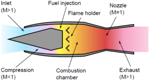
Ramjet engines are a jet propulsion system with a simple aerodynamic principle. They rely on the forward speed of the vehicle to compress the incoming air. This type of engine does not have rotating mechanical compressors, as in turbine engines. A typical ramjet engine consists of three main sections: the diffuser, the combustion chamber, and the nozzle, as shown in Figure 1. They are used in guided missiles, hypersonic aircraft, and certain combined propulsion systems [1].
Figure 1. Ramjet engine
The performance and flow characteristics of a ramjet engine are changed by inlet conditions, such as airspeed and altitude. Altitude plays an important role in determining engine efficiency, fuel economy, combustion stability, and combustion emissions.
The basic operating principle involves converting the kinetic energy of the incoming air into static pressure. The inlet section is shaped to decelerate the high-speed airflow and increase its pressure and temperature isotopically.
The compressed air passes into the combustion chamber, where fuel is injected and burned. The high-temperature gases expand through a convergent-divergent nozzle and produce thrust as they accelerate to supersonic velocity [2, 3].
The true brilliance of this design lies in its complete dependence on the forward speed of the vehicle, making it relatively lightweight and simple compared to turboprop engines. However, this same feature also presents the greatest challenge, as engine performance becomes inextricably linked to changing flight conditions, the most important of which is altitude. Therefore, a precise understanding of how flow characteristics within a ramjet change with altitude is of practical importance for the design of all ramjet engine sections [4].
Many studies exist in this field, but no integrated methodology combines analytical methods and numerical modeling for predicting the operating envelope with systematic experimental verification.
Therefore, this research aims to validate the semi-empirical analytical model based on isentropic relationships and performance equations for predicting flow characteristics through engine components by comparing its results with published experimental data, and by conducting advanced numerical simulations using ANSYS Fluent software with combustion models, and then conducting a quantitative comparison between the two methodologies and determining the optimal operating range in the stratosphere.
The scientific review provides a comprehensive framework for understanding the evolution of knowledge about ramjets from operating principles to design requirements and practical constraints. The authors identified key themes and points in studying multiple issues, such as the role of inlet design, combustion patterns, and the transition to ramjet-scrambled jet hybrid systems. The importance of integrating analytical methods, wind tunnel data, and numerical simulations in the design of practical systems was also reviewed.
Scientific research published through past three decades has focused on three main areas, first- analytical and theoretical studies that build ramjet cycle models and define basic flow-performance relationships; second- numerical studies that attempt to resolve velocity/pressure/temperature fields and chemical interactions within the inlet and chamber; and third- experimental and research studies on flame stability, turbulence, and operational effects (such as pressure recovery losses and dependence on inlet geometry). These areas overlap and complement each other; however, each sheds light on a particular aspect of ramjet design and operation problems.
Research based on analytical and semi-empirical relationships and related tables calculates energy efficiencies, thrust-to-weight ratios, and the effects of inlet conditions on airflow, such as pressure, temperature, and air density. These methods are useful as initial design tools, but they often require corrective equations, especially when flight conditions (speed and altitude) change. Therefore, they are used as a basis for comparison with numerical simulation results or experimental data.
In the field of design, a study by Kummitha et al. [5] provided a comprehensive analysis of the design of ramjet engine inlets. The researchers developed mathematical relationships linking inlet shape to pressure efficiency at various flight conditions. Since the 1980s, numerical studies have accelerated to simulate flow fields within ramjet sections and the combustion chamber. Early studies, such as Drummond’s work [6], developed software to solve the Navier–Stokes equations for airflow and fuel interaction in ramjet sections. Subsequently, several works, such as that of Hsieh and Liu [7], implemented three-dimensional RANS simulations with turbulence models including Shear Stress Transport (SST), to analyze mixing and combustion efficiency in validated experimental models. Their results demonstrated that numerical predictions can closely approximate experimental data if numerical modeling is performed carefully, including model and mesh construction, solution method selection, and turbulence model selection. Choubey et al. [8] also provided a comparison of various turbulence models used in ramjet flow simulations. The study showed that the k-ω SST model gives the most accurate results in mixing regions. However, this study focused on a specific injector design without exploring the systematic effect of altitude.
Recent studies suggest that today's numerical modeling is capable of accurately quantifying the distribution of fields pressure, velocity, temperature, combustion, and fuel economy. For the validation process, studies based on experimental data also provide an important basis for verifying the accuracy of analytical methods and numerical models. In this context, Smart [9] provided comprehensive benchmark data for airflow in jet engine inlets at supersonic Mach numbers. The study relied on accurate pressure and temperature measurements in a supersonic wind tunnel and demonstrated good agreement between the experimental results and numerical simulation.
Rolim and Toro [10] studied the effect of altitude on the flow properties of the combustor and nozzle for scramjets. The results showed the most noticeable difference was found in the maximum pressure position. Also, a study by Wu and Wei [11] provided a comprehensive analysis of the adaptation of the combustion process to altitude variation. The study demonstrated that low inlet pressure at high altitudes leads to difficulties in flame stability and fuel combustion.
Recent numerical studies have noticeably advanced the understanding of kerosene combustion in supersonic flows. Guo et al. [12] conducted a comparative analysis of dual-combustion ramjet and scramjet performances, demonstrating that combustion efficiency decreases with increasing Mach number. The interaction between shock waves and fuel injection has been studied. Abdollahi et al. [13] demonstrated that upstream shock waves improve fuel mixing in scramjet engines. Their computational fluid dynamics (CFD) analysis showed that shock-induced mixing can increase combustion efficiency by up to 15% at high-altitude conditions. The operational challenges related to altitude variations have been addressed by Cervenko and Friedman [14], who established that the ramjet optimal operating range lies between Mach 2.7 and 4.0, validating the stratosphere-operational envelope (17-18 km) proposed in the present analytical framework.
Previous studies show that a research gap remains in understanding the comprehensive effect of altitude (0–18 km) on internal flow characteristics across all engine components. Previous analytical studies [15, 16] relied on simplified assumptions that neglected losses in the combustion chamber and the effects of turbulence. Meanwhile, numerical studies [8, 11] focused on specific operating conditions without systematically exploring a wide range of altitudes, and the lack of standard experimental data across the 0–18 km range hinders comprehensive validation.
Analytical modeling is an important tool for understanding the general changes in flow characteristics with altitude. Based on the results of the analytical modeling of the governing equations of airflow within the engine, based on the laws of thermodynamics and the isentropic relationships, it is observed that flight altitude has a major effect on the basic flow variable [15].
3.1 The model studied
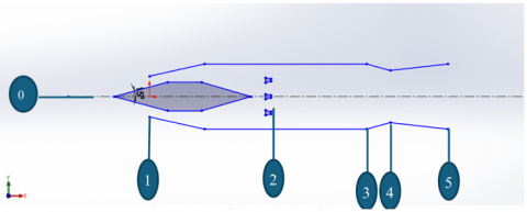
The ramjet engine to be studied is a standard model that has undergone experimental studies. These results will be used to conduct the validation process using both analytical and semi-experimental methods and numerical modeling methods [16]. This engine operates on a kerosene-air mixture, designed to fly in the stratospheric layer of the atmosphere at an altitude of 12 km. The engine operates in the critical mode at a zero angle of attack. The air intake features a conical spike. At this altitude, 12 km, the air density is 0.3 kg/m³, and the temperature in the stratosphere is constant at 216.5 K. The engine flies at an initial velocity of 442 m/s, with an ambient pressure of 19,000 Pa. The following diagram illustrates the engine schematic, where the flow inside the combustion chamber is subsonic; the pressure drop in the combustion chamber was neglected. The air intake diameter d1 is 0.25 m, and the combustion chamber diameter d2 is 0.40 m. The reference area based on d1 and d2 is A1 = 0.049 m2, A2 = 0.12566 m2. The engine consists of the parts shown in Figure 2.
Figure 2. Ramjet engine section studied
Figure 2 shows a simplified schematic of a ramjet engine, where symbol (0) indicates the flight conditions (flight Mach $M_o$ and flight altitude H0), symbol (1) indicates to air inlet conditions, (1-2) is diffuser section with injector assembly, (2-3) is combustion chamber section, (3-5) is convergent-divergent nozzle, where the total length of the engine is 1.84 m, and the length from the air inlet to the beginning of the combustion chamber is 1 m.
The dimensions of this engine were verified and confirmed to meet the design relationships using analytical methods [3, 15, 16]. Combustion is completed entirely within a constant area combustion chamber with a Mach number of M3 = 0.4 at the exit, where $\sum M$ sections ratio from isotropic tables [15, 16]:
$\begin{gathered}M_3=0.4 \Rightarrow \sum M_3=\frac{A_3}{A_4}=1.5901 ; A_2=A_3 \\ A_4=0.079 \mathrm{~m}^2 \Rightarrow d_4=0.317 \mathrm{~m}\end{gathered}$
3.2 Estimating flow parameters and engine performance
The efficiency of the air intake $\eta_{o 2}$ as a function of Mach number of the free stream flow $M_o$ using empirical relations when $M_o \geq 1.5$.
$\eta_{o 2}=1-0.1\left(M_o-1\right)^{\frac{3}{2}}$ (1)
On the other hand, the air effectiveness relationship is given [13]:
$\eta_{o 2} \frac{A_2}{\xi A_1}=\frac{\sum M_2}{\sum M_o} \Rightarrow \sum M_2=\eta_{o 2} \frac{A_2}{\xi A_1} \sum M_o$ (2)
We get Mach number of intakes $M_2$ from relationship and isotropic tables [16].
The estimation of the stagnation temperature for the combustion chamber inlet by analytical methods is done using the following relationship [3, 16]:
$T_{i 2}=T_o\left(1+\frac{\gamma-1}{2} M_o^2\right)$ (3)
The symbol i indicates the stagnation values at each section of the engine, while the other values indicate the static parameters. The determination of temperature $T_{i 3}$ and fuel-to-air ratio f is taken from the kerosene air combustion diagram [15].
$M_2=f\left(M_3, T_{i 2}, T_{i 3}\right) \Rightarrow T_{i 3}=f\left(M_3, T_{i 2}, M_2\right)$ (4)
$Equivalence \,\,ratio \,\, \varphi=\frac{\left(\frac{f u e l}{{ air }}\right)_{ {actual }}}{\left(\frac{f u e l}{ { air }}\right)_{ {stoich }}}=\frac{f}{f_{s t}}$ (5)
Table 1 illustrates the change in engine parameter values with a change in Mach number at an altitude of 12 km.
Table 1. Engine parameter values
|
$M_o$ |
1.5 |
1.75 |
2 |
2.15 |
|
$\eta_{o 2}$ |
0.965 |
0.935 |
0.91 |
0.877 |
|
$\sum M_o$ |
1.176 |
1.387 |
1.688 |
1.919 |
|
$\sum M_2$ |
2.9 |
3.32 |
3.89 |
4.31 |
|
$M_2$ |
0.205 |
0.18 |
0.15 |
0.135 |
|
$T_{i 2}[k]$ |
315 |
350 |
390 |
417 |
|
$\Delta T_i[k]$ |
500 |
770 |
1290 |
1830 |
|
$T_{i 3}[k]$ |
814 |
1119 |
1680 |
2250 |
|
$f$ |
0.013 |
0.02 |
0.036 |
0.064 |
|
$\varphi$ |
0.191 |
0.294 |
0.529 |
0.936 |
Table 2. Pressure, temperature, Mach number, and velocity values at various engine stations
|
Section |
0 |
2 |
3 |
4 |
5 |
|
$P[p a]$ |
11572 |
80227.2 |
69429 |
36230.5 |
9771 |
|
$P_i[p a]$ |
90553 |
81497.8 |
68582.1 |
68582.1 |
68582.1 |
|
$T[K]$ |
218 |
390.64 |
1681.86 |
1402 |
964.13 |
|
$T_i[K]$ |
392.4 |
392.4 |
1682.4 |
1682.4 |
1682.4 |
|
$M$ |
2 |
0.15 |
0.4 |
1 |
1.93 |
|
$V[{m} / {sec}]$ |
592.1 |
59.44 |
329.3 |
751.67 |
1203 |
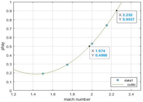
Based on the geometric configuration of the engine defined in the previous figure and during its operation within the stratospheric layer of the atmosphere, the acceptable range of Mach number variations will be determined. This is to ensure the engine's operating condition regarding the equivalence ratio is satisfied at a value of $0.5 \leq \varphi \leq 0.9$ deviation from this range leads to engine flameout, as shown in Figure 3. We conclude that the studied engine is operating stably within the range of Mach number $\left(1.97 \leq \mathrm{M}_{\mathrm{o}} \leq 2.25\right)$.
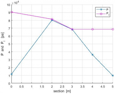
Assuming the engine operates at Mach $\mathrm{M}_{\mathrm{o}}=2$ and the flow within the nozzle is isotropic and adiabatic. We will calculate the static pressure, stagnation pressure, static temperature, stagnation temperature, Mach number, and velocity at various engine stations as illustrated in Figures 4 and 5. We divided these stations into five sections.
Figure 3. Equivalence ratio with Mach number
Figure 4. Static, stagnation pressure at various engine stations
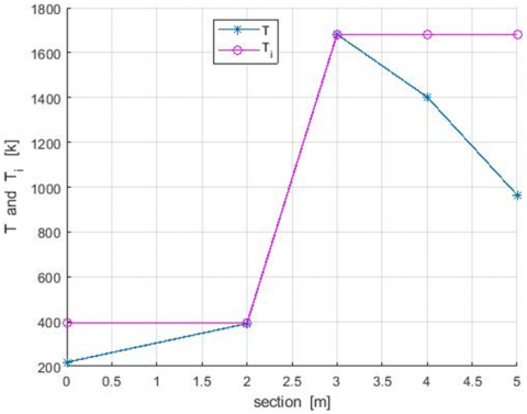
Figure 5. Static, stagnation temperature at various engine stations
Table 2 shows the values of various flow rates, including pressure, temperature, speed, and Mach number, at different engine sections.
Figures 2 and 3 show the values of pressure and temperature at different engine sections. We note from the results at height 12 km that the maximum values for both the stagnation pressure and temperature are at the engine inlet and the engine nozzle.
$\frac{P_o}{P_{i_o}}=\left(1+\frac{\gamma-1}{2} M_o^2\right)^{-\frac{\gamma}{\gamma-1}} \Longrightarrow P_{i_o}=\frac{P_o}{\left(1+\frac{\gamma-1}{2} M_o^2\right)^{-\frac{\gamma}{\gamma-1}}}$ (6)
$\eta_{02}=\frac{P_{i_2}}{P_{i_o}}$ (7)
$\eta_{24}=\frac{P_{i_4}}{P_{i_2}}=\frac{w\left(M_2\right)\left(1+\gamma_2 M_2^2\right)}{w\left(M_4\right)\left(1+\gamma_4 M_4^2\right)}$ (8)
$P_{i_4}=P_{i_2} \times \eta_{24} \Rightarrow P_4=P_{i_4}\left(1+\frac{\gamma_4-1}{2} M_4^2\right)^{-\frac{\gamma_4}{\gamma_4-1}}$ (9)
$T_{i_4}=T_{i_3}, T_4=\frac{T_{i_4}}{\left(1+\frac{\gamma_4-1}{2} M_4^2\right)}$ (10)
$V=M \times a \Rightarrow V=M \sqrt{\gamma R T_4}$ (11)
$P_{i_5}=P_{i_4} \Rightarrow P_5=P_{i_5}\left(1+\frac{\gamma_5-1}{2} M_5^2\right)^{-\frac{\gamma_5}{\gamma_5-1}}$ (12)
3.3 Validation process
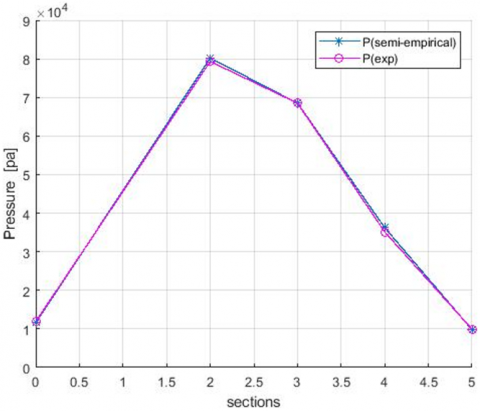
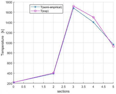
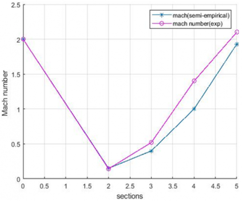
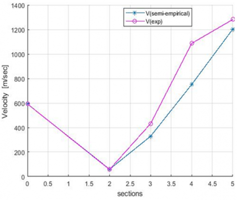
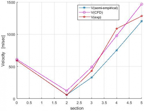
Validation was carried out by comparing the flow parameters estimated using analytical and semi-empirical methods with experimental results for the studied engine at an altitude of 17 km and Mach number 2 [16]. The results are shown in Figures 6-9.
We note that the results are consistent with the flow pressure values in all engine sections, while we note differences in the temperature and speed values in the engine sections before and after the combustion chamber.
Figure 6. The static pressure at various engine stations
Figure 7. Static temperature at various engine stations
Figure 8. Mach number at various engine stations
Figure 9. Velocity at various engine stations
3.4 Study the effect of altitude on the flow characteristics and performance of the engine
Analytical studies, validation process, and a review of the literature collectively identify that the second engine section, the diffuser section with injector assembly before the combustion chamber, is the most susceptible to altitude changes, as shown in Figure 2. Therefore, the effect of altitude will be studied in this section. The study will also be conducted at Mach number 2, which achieves the best performance, according to the semi-empirical relationships that were validated based on the study [16]. The effect of flight altitude, from sea level to 18 km, on the flow and performance characteristics of the engine at the second section was investigated using isentropic relations according to Eqs. (3)-(12).
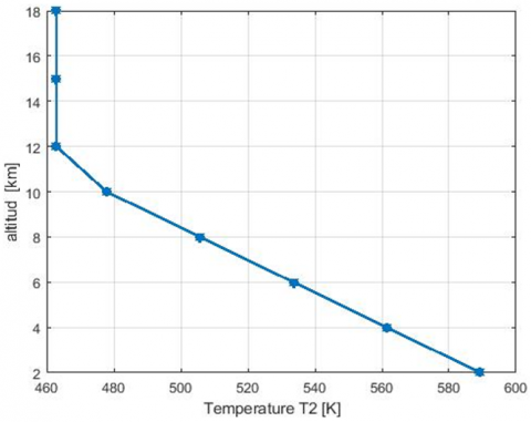
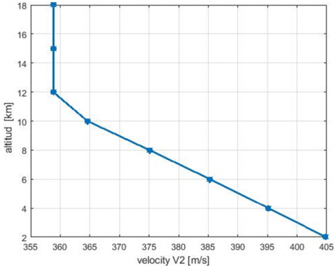
Figures 10 and 11 show that the maximum changes in both temperature and speed occur at altitudes below the stratosphere up to 12 km, but that the changes in both temperature and speed remain small within the stratosphere. Therefore, the effect of altitude on pressure within the engine's optimal operating region within the stratosphere will be studied to determine the operating altitude using analytical methods. In the range of Mach number Mo = [1.98, 2.05, 2.12] that satisfy the engine operability condition in terms of equivalence ratio and stratospheric flight condition H = [12.20, 15.25, 18.30 km], the objective is to determine the maximum flight altitude corresponding to Mach numbers such that the air pressure at the combustion inlet does not fall below 0.6 atmospheres.
Figure 10. Change temperature T2 with altitude
Figure 11. Change velocity V2 with altitude
Table 3. Values Pi2 [atm] with Mach number and altitude
|
H |
M = 1.98 |
M = 2.05 |
M = 2.12 |
|
12.20 km |
1.23 |
1.39 |
1.54 |
|
15.25 km |
0.78 |
0.86 |
0.95 |
|
18.30 km |
0.48 |
0.53 |
0.59 |
Table 4. Values P2 [atm] with Mach number and altitude
|
H |
M = 1.98 |
M = 2.05 |
M = 2.12 |
|
12.20 km |
1.24 |
1.37 |
1.52 |
|
15.25 km |
0.77 |
0.85 |
0.94 |
|
18.30 km |
0.48 |
0.53 |
0.58 |
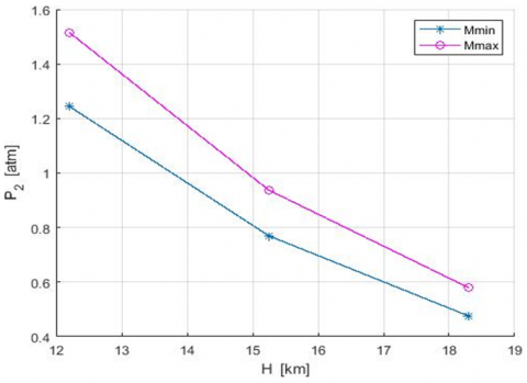
Figure 12. Mach number with pressure and altitude
Based on Eq. (3) and the air conditions at the engine inlet from the air tables at the studied altitudes, the values of the stagnation pressure at P0 at the engine inlet have been calculated, and then based on the air intake efficiency in Eq. (7), the stagnation pressure values Pi2 have been calculated as shown in Table 3.
Static pressure P2 variations at the combustion chamber inlet are tabulated based on Eq. (6) in Table 4 and Figure 12.
From the calculated results and through the interpolation process, the pressure is around 0.6 atmospheres, which previous results have shown to achieve the best performance in the range of altitudes between Hmin = 17 km and Hmax = 18.15 km, and in the range of Mach numbers is [1.98 ~ 2.12].
Thus, the engine operating regime is delineated between these altitude limits and across the given Mach number range Mo = [1.98 ~ 2.12].
4.1 Model and mesh setup
Numerical modeling of the airflow within the ramjet engine sections was performed using ANSYS Fluent 16. The model relied on solving the Navier-Stokes equations to accurately analyze the flow characteristics across the various engine components [17].
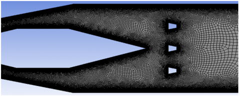
The geometric model was built using SolidWorks software, including the main engine components: the inlet, combustion chamber, and nozzle. An unstructured mesh was created in some areas far from the wall and combustion chamber, with a regular mesh in critical regions such as the boundary layer, fuel injection zones, and areas of steep property gradients, as shown in Figure 13.
A grid independence study was conducted by creating three meshes: a coarse mesh with 224,354 elements, a medium mesh with 755,268 elements, and a fine mesh with 1,213,543 elements. The pressure, velocity, and temperature values at Mach number 2 and altitude of 12 km were compared with reference values obtained from experimental and analytical methods. The second medium mesh was adopted as it achieved good convergence. An unstructured mesh was created in the regions far from the wall, and a structured mesh with a boundary layer was created near the wall, achieving the W Plus number y+ ≈ 1 near the walls, as shown in Figure 14, which meets the requirements of the turbulence model used. This was compared to reference values obtained using experimental results. The study and determination of the boundary layer is crucial for modeling the flow near the wall, which determines the turbulence model used in the numerical solution. We define the first cell height 0.0001 m, growth ratio 1.2 and number of layers 15 in the mesh.
Figure 13. Boundary conditions
Figure 14. Mesh and boundary layer
4.2 Solution setting
Numerical modeling of the flow inside the studied engine using the ANSYS Fluent 16 program is done by numerically solving the Navier-Stokes equations according to the density-based, energy equation, and the species equations for chemical reactions, and by using a second-order upwind scheme for all variables. The reference length used in the modeling is the length of the engine. To model the effects of turbulence, the k-ω SST model was used, which provides high accuracy in predicting boundary layer separation and energy and heat transfer in the near-wall regions [18, 19]. The pressure drop in the combustion chamber is captured by the momentum equations. The combustion process was simulated using a non-premixed combustion model, where the mixture was defined using a mixture fraction function, taking into account the chemical interaction between kerosene and air [8]. For modeling the combustion process, a Finite-Rate/Eddy-Dissipation model was used, which combines rate-limited chemical reaction control and turbulent mass transfer. The chemical reaction was defined using an 8-component kerosene-air reaction mechanism. The numerical modeling of combustion in the combustion chamber using ANSYS Fluent is achieved by implementing a reaction rate model and defining the molecular weights for the fuel and oxidizer species, consistent with the chemical combustion equation and its resultant products [19].
$Fuel\left({C}_{12} {H} 23\right)+Oxidizer \left(\mathrm{O}_2\right) \rightarrow Combustion \,\, Products \left(\mathrm{CO}_2+\mathrm{H}_2 \mathrm{O}\right)+Heat$
4.3 Numerical modeling results
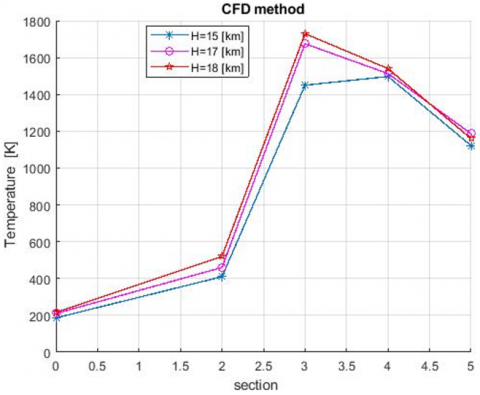
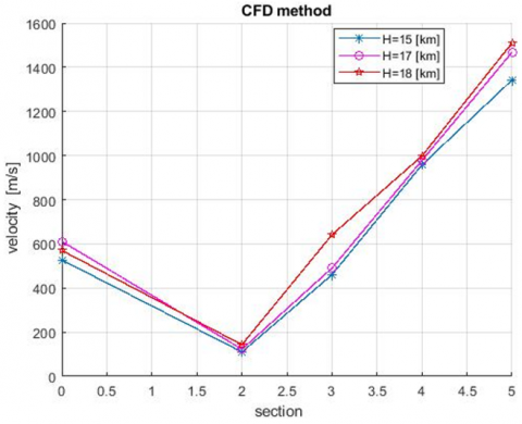
Numerical modeling of the flow inside all the sections of the studied ramjet engine was performed using the ANSYS Fluent software at altitudes from 15 km to 18 km and at a Mach number of 2, based on the findings of the analytical study.
Figures 15 and 16 illustrate the changes in both velocity and static temperature across various engine sections, from the inlet to the combustion chamber to the nozzle, at different engine operating altitudes. The figures illustrate the changes in flow characteristics and, consequently, engine performance across the various engine sections, from the inlet to the combustion chamber to the nozzle, at different engine operating altitudes.
Figure 15. Static temperature at various engine stations and at various altitudes
Figure 16. Velocity at various engine stations and at various altitudes
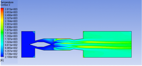
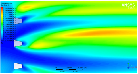
Figure 17. Temperature contour, M = 2 and H = 17 km
Figure 18. Temperature contour, M = 2 and H = 17.5 km
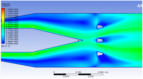
Figure 19. Velocity contour, M = 2 and H = 12 km
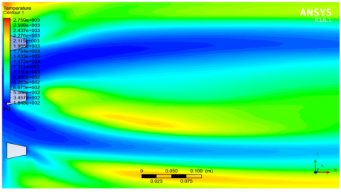
Figure 20. Temperature contour, M = 2 and H = 18 km
Figure 15 and Figure 16 illustrate the changes in flow characteristics and, consequently, engine performance across the various engine sections, from the inlet to the combustion chamber to the nozzle, at different engine operating altitudes.
From the numerical modeling results and the temperature and velocity counters shown in Figures 17-20, it is noted that the greatest effect of altitude on static temperature in the studied range is in the combustion chamber and beyond the combustion chamber.
The results derived from this study demonstrate remarkable agreement between the analytical calculations and semi-empirical methods, on the one hand, and the experimental reference results, on the other, especially about the pressure and velocity values in the engine Inlet, the pre-chamber region, and the nozzle. The differences in these regions do not exceed 5%, confirming the reliability of the analytical models in these parts of the engine. It indicates the dominance of isentropic physics in these regions. This is consistent with the conclusions of Heiser and Pratt that viscosity effects are secondary in regions with high pressure gradients and smooth profiles. However, the slight difference (5%) is mainly attributed to the k-ω SST turbulence model in the numerical simulation, which captures the small pressure loss in the boundary layer that idealized isentropic relationships ignore.
However, the most striking differences appear in the combustion chamber, where the numerical results demonstrate a higher accuracy in representing the temperature distribution. This is due to their ability to fully represent the combustion phenomenon and the fuel-air mixing process using appropriate turbulence models.
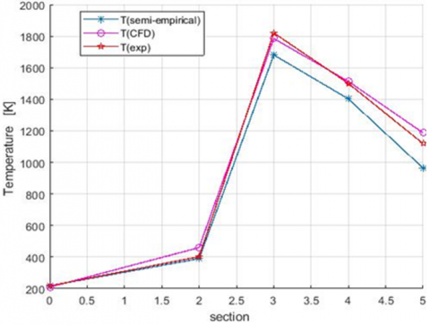
High temperatures are recorded in the combustion chamber through numerical modeling, reaching approximately 2,000 K, with flow stability observed at various points along the engine's length. It is worth noting that the maximum difference between the analytical and numerical methods does not exceed 20% for temperature and velocity, as illustrated in Figures 21 and 22. The largest relative difference between the analytical and numerical methods, approximately 20%, occurs in the combustion chamber region, indicating an acceptable degree of agreement between them. While the analytical model assumes uniformly distributed combustion, numerical simulations reveal the presence of mixing fuel-air and asymmetrical thermal fields. This phenomenon, similar to that observed in Choubey et al. [8], arises from the complex interaction between fuel injection, turbulence vortices, and the reaction rate-limited combustion chemistry. This difference explains why analytical models require corrective factors to compensate for these complexities.
Figure 21. Comparison of static temperature values between analytical and numerical methods
Figure 22. Comparison of velocity values between analytical and numerical methods
One of the important findings of this study is that the altitudes that achieve the best engine performance in terms of fuel efficiency and ensuring stable combustion are in the range of 17 to 18 km, and at the Mach number 2, where the optimal conditions for pressure and density are available for efficient combustion while minimizing energy loss.
The analytical and numerical methods can be considered effectively complementary. Analytical methods provide results with good accuracy and rapid implementation in the preliminary design phase and in areas such as the engine inlet. Numerical methods, on the other hand, excel in providing more accurate results in the combustion chamber and post-combustion regions, and provide a comprehensive explanation of the physical phenomena associated with flow through all engine components. This integration between the two methodologies can form an effective framework for the design of ramjet engines.
This study developed an integrated (analytical-numerical) methodology to evaluate the effect of altitude (0–18 km on the internal flow of a standard ramjet engine. The analytical methods included determining various flow characteristics, pressure, temperature, and velocity values for all parts. The results showed good agreement with reference experimental data.
The results showed that analytical methods demonstrated high accuracy in predicting the inlet and nozzle flow pressure and velocity when verified against experimental data (5%), confirming their validity as a tool for preliminary estimation and operating range determination. It showed that optimal performance is achieved at an altitude of 17 km and Mach 2.
Numerical simulations using ANSYS Fluent revealed complex details of the combustion process within the combustion chamber, including localized hot spots reaching ~2000 K, which the simplified analytical model failed to fully capture (differences up to 20%). An optimal operating range for the engine in the stratosphere was determined to be between 17–18 km altitudes and Mach 1.98–2.12, where an inlet pressure of at least 0.6 atmospheres ensures sufficient flame stability.
Numerical simulations were performed using ANSYS Fluent 16 to model complex details of flow and combustion process within the combustion chamber within the specified operating range. The results showed good agreement with the analytical methods for the flow characteristics at the engine inlet, while showing relative differences (20%) in the temperature values of combustion chamber section that reached to 2000 K, an optimal operating range for the engine in the stratosphere was determined to be between 17–18 km altitudes and Mach 1.98–2.12, where an inlet pressure of at least 0.6 atmospheres ensures flame stability.
The study suggests, based on these findings and limitations, the following research directions: improving the analytical models by including more semi-empirical relationships for combustion chamber pressure loss and mixing efficiency, for the elevation effect, and extending the numerical modeling by performing Large Eddy Simulation (LES) to gain a more accurate understanding of turbulence and mixing.
[1] Heiser, W.H., Pratt, D.T. (1994). Hypersonic Airbreathing Propulsion. American Institute of Aeronautics and Astronautics, Inc. https://doi.org/10.2514/4.470356
[2] Baidya, R., Pesyridis, A., Cooper, M. (2018). Ramjet nozzle analysis for transport aircraft configuration for sustained hypersonic flight. Applied Sciences, 8(4): 574. https://doi.org/10.3390/app8040574
[3] S, K.S.D., Khandai, S.C. (2015). Design and development of a subsonic ramjet for experimental comparison of biofuel with jet fuel. International Journal of Applied Engineering Research, 10(23): 43328-43335. https://www.researchgate.net/publication/288003939_Design_and_Development_of_a_Subsonic_Ramjet_for_Experimental_Comparison_of_Biofuel_with_Jet_Fuel.
[4] Bhandarkar, A., Basu, S., Manna, P., Chakraborty, D. (2016). Aerodynamic characterisation of ramjet missile through combined external-internal computational fluid dynamics simulation. Defence Science Journal, 66(6): 624-629. https://doi.org/10.14429/dsj.66.9677
[5] Kummitha, O.R., Suneetha, L., Pandey, K.M. (2017). Numerical analysis of scramjet combustor with innovative strut and fuel injection techniques. International Journal of Hydrogen Energy, 42(15): 10524-10535. https://doi.org/10.1016/j.ijhydene.2017.01.213
[6] Drummond, J.P. (1985). Numerical study of a ramjet dump combustor flowfield. AIAA Journal, 23(4): 604-611. https://doi.org/10.2514/3.8957
[7] Hsieh, K.C., Liu, J.S. (1989). Numerical investigation of chemically reacting flows in ramjet dump combustors. In 27th Aerospace Sciences Meeting, Reno, NV, U.S.A., p. 387. https://doi.org/10.2514/6.1989-387
[8] Choubey, G., Solanki, M., Patel, O., Devarajan, Y., Huang, W. (2023). Effect of different strut design on the mixing performance of H2 fueled two-strut based scramjet combustor. Fuel, 351: 128972. https://doi.org/10.1016/j.fuel.2023.128972
[9] Smart, M.K. (2001). Experimental testing of a hypersonic inlet with rectangular-to-elliptical shape transition. Journal of Propulsion and Power, 17(2): 276-283. https://doi.org/10.2514/2.5774
[10] Rolim, T.C., Toro, P.G.P. (2015). Preliminary analysis of scramjet engines based on engineering models, Aerospace Science and Technology, 47: 256-268. https://doi.org/10.1016/j.ast.2015.09.010
[11] Wu, X.J., Wei, Z.J. (2023). Comparison of dual-combustion ramjet and scramjet performances considering combustion efficiency. Applied Sciences, 13(1): 480. https://doi.org/10.3390/app13010480
[12] Guo, F., Liu, M., He, G.Z., Zhou, J.H., Zhu, J.F., You, Y.C. (2023). Analysis and suppression of thrust trap for turbo-ramjet mode transition with the integrated optimal control method. Aerospace, 10(8): 667. https://doi.org/10.3390/aerospace10080667
[13] Abdollahi, S.A., Jafar, M., Aminian, S., Fattahi, M., Uyen, P.D. (2023). Fuel mixing enhancement of transverse coaxial air and fuel jet by upstream shock wave in scramjet engines: Numerical study. Scientific Reports, 13: 18501. https://doi.org/10.1038/s41598-023-45810-z
[14] Cervenko, A.J., Friedman, R. (1956). Ram-jet performance. In Adaptation of Combustion Principles to Aircraft Propulsion. Volume II–Combustion in Air-Breathing Jet Engines. https://ntrs.nasa.gov/citations/19670095387.
[15] Carriere, P. (1972). Internal Aerodynamics, Nozzles and Jets, Part 2 (in French). Toulouse: École Nationale Supérieure de l’Aéronautique et de l’Espace. https://catalogue1.biblio.enp.edu.dz/index.php?lvl=serie_see&id=845.
[16] ANSYS Inc. (2015). ANSYS Fluent 16 Manual. https://www.scribd.com/document/380815967/ANSYS-Fluent-Migration-Manual-16-0.
[17] Veeran, S., Pesyridis, A., Ganippa, L. (2018). Ramjet compression system for a hypersonic air transportation vehicle combined cycle engine. Energies, 11(10): 2558. https://doi.org/10.3390/en11102558
[18] Teon, R.Y. (2021). Conceptual study of an internal flowpath of a vertically-cruising ramjet. Doctoral dissertation. San José State University.
[19] Javed, A., Chakraborty, D. (2018). Numerical simulations of static tested Ramjet dump combustor. Journal of the Institution of Engineers (India): Series C, 99(4): 419-427. https://doi.org/10.1007/s40032-016-0312-3