Afyaa Saad Neamaha![]() | Ali Fadhil Naser*
| Ali Fadhil Naser*![]()
© 2025 The authors. This article is published by IIETA and is licensed under the CC BY 4.0 license (http://creativecommons.org/licenses/by/4.0/).
OPEN ACCESS
The methodology of this study consisted of selecting the bridge structure, creating a bridge model by using CSI-Bridge Ver. 25, applying ground movement within bridge location as earthquake load, using modal analysis method and demand/capacity ratio method to evaluate the seismic resistance of bridge structure. The results showed that the average value of seismic natural frequency is small and equal to 1.566 Hz which is small value, indicating insufficient stiffness and elasticity. For the transverse direction (Y) representing the cross-section of the bridge, the magnitudes of D/C ratio are similar for each bent with the maximum value equal to 0.4484 at bent No. 5, which is lower than 1. But in longitudinal direction of bridge line (X), the D/C ratio for all bents is near and equal to 2.396 as maximum value within bent No. 5 which much greater than 1, indicating that the demand is more than capacity of bridge bents and they can’t resist the earthquake lateral load. This study suggested to increase the piers diameter to increase the size of bridge piers, leading to improve the structural performance, stiffness, elasticity, bearing capacity of bridge piers to resists the earthquake action and the increasing of piers diameter is 1.6 m, 1.8 m, and 2 m. The analysis showed than the increasing of piers diameter leads to an increase the seismic natural frequency and decreasing of D/C ratio for all bents with diameters 1.8 m and 2 m.
earthquake, seismic design, I-girder, modal, natural frequency, demand, capacity
A bridge is a man-made structure that crosses physical barriers, such as a valley, a canal, or a highway, without blocking traffic below. Bridge type selection is based on site characteristics, vendor preferences, site hydraulics, profile location, and construction cost. The density and volume of traffic loads determine the size of the bridge structure, which is crucial for the region that the bridge connects [1-6].
Bridge structures are important and capable structures that have many different parts. There are two elements to these components. The first components are the drainage system, pavement layers, joints, deck, girders or beams, bearings, and security barrier. Superstructure was the name given to them. The foundations, piers, and pier caps made up the second section, which was referred to as the substructure. It is possible to build bridges across obstacles like rivers, roads, and railroads. Bridge constructions may be categorised based on the kinds of supports and materials used. Concrete, pre-stressed concrete, wood, and steel bridges are among the several kinds of bridges based on the materials used in their construction. Simply supported bridges and continuous bridges are two examples of the sorts of supports used in bridge constructions [7-14].
The pre-stressed concrete bridge system handles applying tendons loads to the bridge structure before to applying service loads, which include traffic loads, dead loads, temperature loads, wind loads, and live loads. There are two types of prestressed concrete systems. Pre-tensioning is the first kind. Post-tensioning is the second kind. Post-tensioning is a technique for reinforcing concrete structures using tendons, which are strong steel strands or bars [15-18].
Following an earthquake and the emergence of overload-related damages, every bridge should be inspected in order to get data on its structural sufficiency and condition. It is necessary to save this data as a permanent bridge record. An accurate and helpful history is provided by such a record. It also gives people easy access to information and includes details about prior fixes. In addition to being crucial for the economics of an area, damage inspection and maintenance of all kinds of bridges are necessary for the safety of bridge users. Bridge component inspection must be intimately linked to any successful bridge maintenance program. As a result, the maintenance division needs to employ an inspection team, which is a permanent group of inspectors. Every component of the bridge is examined throughout the inspection process to determine if it is in excellent condition or requires strengthening or repair. Review reports, site conditions, required tools and equipment, traffic control (if required), site survey, and structural inspection—which includes deck, superstructure, and substructure inspections—are all included in the inspection plan [12, 19-27].
The strengthening of key bridge components effectively increases the strength and stiffness of structural members, and the repair process entails restoring the strength and functionality of the damaged members in order to increase the resistance of the bridge structure to earthquake action and other damages. The bridge structural members can be strengthened by adding more load-bearing materials, redistributing the loading activities by imposing deformation on the structure system, and replacing subpar or defective elements with better ones. Numerous considerations determine which approach is best for fortifying and repairing the bridge's structural members. These elements include the kind and age of the structure, its significance, the amount of strength that must be increased, the kind and extent of damage, the materials that are available, the cost and viability, and aesthetics. The bridge structure may be strengthened and repaired in an efficient manner [28-33].
The shifting of the earth's strata through vibration, distortion, and slide is known as an earthquake. Strong earthquakes can be the primary cause of the shifting earth's crust. First, the layer may bow, after which it may burst, settle, and shift to a new spot. Seismic waves are the result of rupture and tremors. Seismic waves may be produced following a fault rupture. Seismic waves are classified into two categories. Body waves, which include longitudinal P waves and transversal S waves, are the first kind. Surface waves are the second type. Special detailing of the rear wall and its foundations is required to withstand the huge stresses that earthquakes can apply to bridge constructions' abutments and bends [34-36].
The seismic design of bridge structures must be conducted according to two levels of evaluation. The initial level is the Safety Evaluation Earthquake (SEE), which represents the higher threshold, and the subsequent level is the Functionality Evaluation Earthquake (FEE), which represents the lower threshold. Following a seismic safety assessment, the bridge structure must continue to operate. The earthquake load and reaction spectrum must be taken into account in both safety and functioning evaluations. The goals of seismic design for bridges are to keep critical structural components within the elastic range during a SEE and to make sure that the bridges are safe, reliable, serviceable, constructible, and maintainable when they have energy dissipation and isolation devices [37, 38].
The measure known as the demand to capacity ratio (D/C) was initially proposed by the Applied Technology Council (ATC). The ability of structural components to withstand the pressures and displacements brought on by earthquake activity is contrasted with the internal forces and displacements that arise from employing an elastic analysis for design earthquake (demand). A demand to capacity ratio greater than one indicates that the structural member is likely to fail and that retrofitting is necessary. When the ductility is measured in the section, the demand to capacity ratio can be linked to a section ductility demand of two or three. Recent advancements in seismic reaction research have put the demand to capacity technique at risk of more thorough examination. The primary challenge with this approach is that, due to its non-linear behaviour, there is no correlation between the ductility parameter of the member and the structure [39-41].
The modal analysis technique is used in the design and research of civil structures to identify the dynamic features and improve the natural mode frequencies and shapes. Response spectrum analysis, a method commonly used to design civil structures both normally and during seismic activity, may incorporate it. The objective of this approach is to quickly calculate the maximal reaction without the need for response history analysis [42-44].
This study's primary goals are to evaluate the precast I-girder prestressed concrete bridge's seismic design and earthquake action resistance, ascertain modal analysis responses like seismic natural frequency, time, and deformation, calculate the demand to capacity ratio, enhance the seismic resistance through design changes by enlarging the pier diameters, and support the use of the study's methodology in the assessment of seismic resistance for both new and existing bridges.
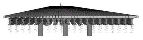
In this study, precast I-girder prestressed concrete bridge is selected to evaluate the seismic resistance of bridge structure under earthquake action and it is located in the center of Babylon city in the middle of Iraq. A bridge structure consists of 19 spans and this study selects 7 spans from bridge structure because of all spans of bridge are same in dimensions and properties. The length of each span is 20 m and the width is 17.5 m. The total length of selected spans is 140 m. The number of precast prestressed concrete I-girders are 20. These 7 spans have two abutments and 6 bents. Each bent has three piers with 1.2 m diameter for each pier. The height of pier is selected as the higher pier in the bridge structure which is 5 m. The compression strength of concrete for girders and bents is 42 MPa and 33 MPa respectively. The type of steel for prestressed tendons is ASTM A416-grade 270 with 7-wires for each strand. Each girder has 13 tendons which are distributing in tension zone. The prestressed force for each tendon is 181 kN. The types of supports are simply supported by adopting pin in start of each span with roller in the end of each span, this permits to decrease the bending moment equal to zero in these types of supports. The type of area object model is shell element with maximum submish size is 1.2 m. Maximum segment length of concrete deck, concrete piers and concrete piers cap is 3 m respectively. Figure 1 presents the bridge structure view and Figure 2 shows the numerical model of selected spans of precast I-girder prestressed concrete bridge. CSI-bridge Ver. 24 is used in this study.
(a) Longitudinal view
(b) Piers view
(c) Transverse view
Figure 1. Bridge structure view
(a) Front view
(b) Side view
Figure 2. Precast I-girder prestressed concrete bridge numerical model
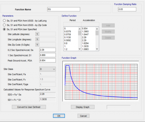
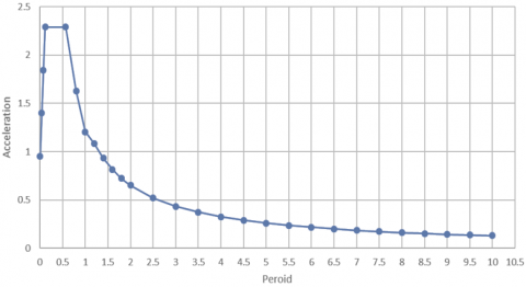
The ground wave threat by implementing the displacement and time period. To take into account the impact of potential seismic activity on the bridge model, which represents the lateral horizontal stress of an earthquake on the bridge structure in both transverse and longitudinal directions, the ground wave hazard must be established. Response Spectrum is chosen as the function type, while ASSHTO 2012 is chosen as the standard because of this function represents the newest seismic function by ASSHTO 2012. The damping ratio is 0.05, and the site class D is chosen which is represent over medium wave hazard of earth movement, and the response spectrum function is called EQ. the factor SDS is equal to 2.29 and SD1 is equal to 1.3035. Site coefficient is 1.5. The curve represents the relation between time or period and acceleration of earth movement. The ground wave hazard curve, often known as the seismic design curve, is seen in Figure 3.
(a) Ground wave function
(b) Acceleration-period relationship curve
Figure 3. Ground wave hazard curve (the seismic design curve)
4.1 Seismic-modal load case
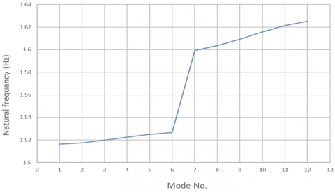
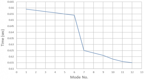
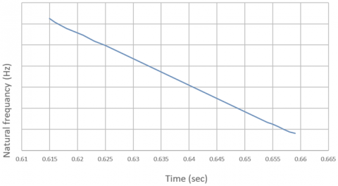
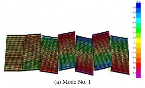
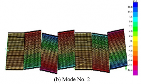
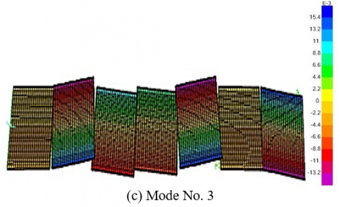
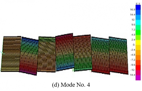
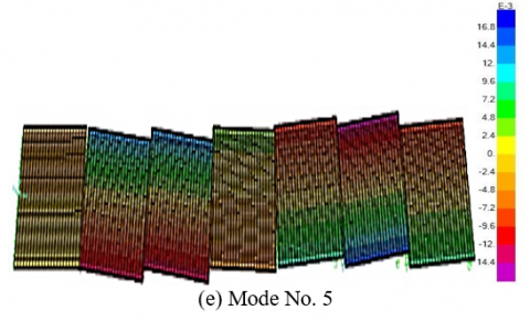
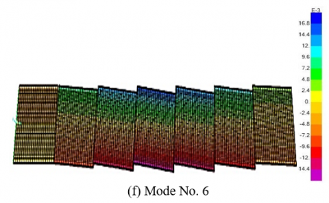
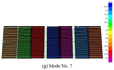
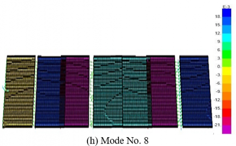
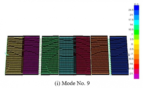
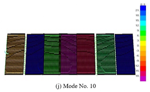
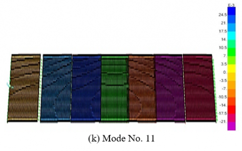
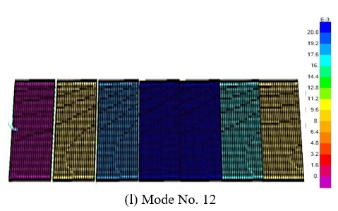
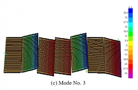
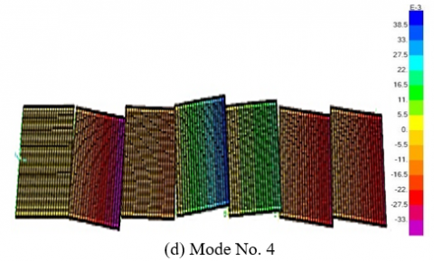
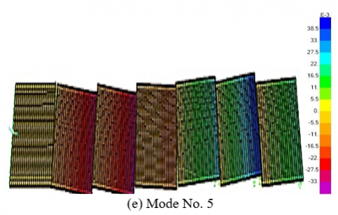
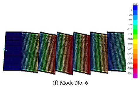
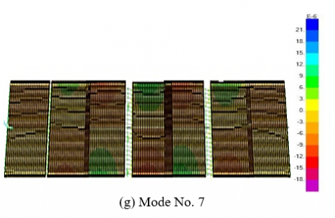
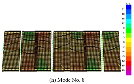
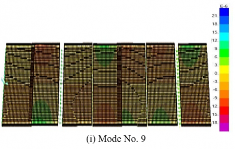
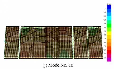
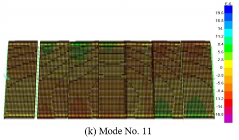
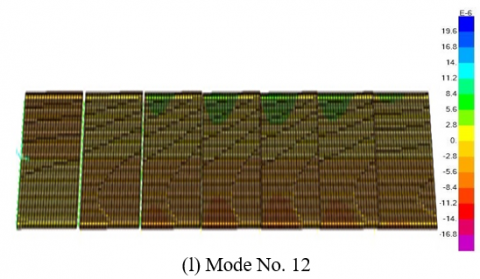
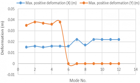
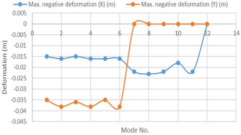
Seismic modal load case analysis is carried out under self-weight of bridge structure which is applied to earthquake lateral load and it is used to find the demand values such as seismic natural frequencies, seismic deformation values (dynamic displacement), and seismic modes shapes. This study will depend on the first 12th mode numbers in longitudinal direction (X) and transvers direction (Y). Tables 1 and 2 lists the modes numbers, time, seismic natural frequency values, seismic deformation values. Whereas, Figure 4 shows the mode numbers and natural frequency. Figure 5 shows the relation between mode numbers and time. Figure 6 shows the relationship between time and seismic natural frequency. Figure 7 shows the mode shapes under effect of earthquake action in longitudinal direction (X), and Figure 8 shows mode shapes in transvers direction (Y). Seismic natural frequency represents the resilience of bridge structure under effect of earthquake lateral action and self-weight of structure without any external loads. In general, the natural frequency is related with elasticity and stiffness of bridge structure. Therefore, the increasing in the magnitude of natural frequency mean that the structural performance of bridge structure in elastic area and it has enough stiffness and bearing capacity with higher resistance to external loads. When the values of natural frequency are small, meaning that the structural performance within plastic area and the bridge stiffness is not enough to resists the external loads. The results shown that the values of natural frequency increased with decreasing the time for modes of bridge structure and the average value of natural frequency is 1.566 Hz which is small value, indicating that the stiffness and elasticity is not enough. Therefore, the bridge structural parts cannot resist the seismic load. The deformation in longitudinal direction (x) has important effect on the seismic natural frequency. The maximum value of positive and negative seismic deformation in X direction is 0.022 m and -0.023 m respectively. For transverse direction (Y), the maximum value of positive and negative deformation is 0.038 m and -0.038 m respectively as shown in Figure 9 and Figure 10. According to the above discussion, the seismic performance of bridge structure due to modal analysis checking needs to improve to prevent the damages of earthquake actions.
Table 1. The modes numbers, time and seismic natural frequency values
|
Mode No. |
Time (sec) |
Frequency (Hz) |
|
1 |
0.659 |
1.5163 |
|
2 |
0.658 |
1.5176 |
|
3 |
0.657 |
1.5199 |
|
4 |
0.656 |
1.5225 |
|
5 |
0.655 |
1.5250 |
|
6 |
0.654 |
1.5267 |
|
7 |
0.625 |
1.5994 |
|
8 |
0.623 |
1.6035 |
|
9 |
0.621 |
1.6093 |
|
10 |
0.618 |
1.6157 |
|
11 |
0.616 |
1.6214 |
|
12 |
0.615 |
1.6252 |
|
Average |
0.638 |
1.556 |
Table 2. The modes numbers and deformation values in longitudinal and transverse direction
|
Mode No. |
Max. Positive Deformation (X) (m) |
Max. Negative Deformation (X) (m) |
Max. Positive Deformation (Y) (m) |
Max. Negative Deformation (Y) (m) |
|
1 |
0.015 |
-0.015 |
0.035 |
-0.035 |
|
2 |
0.016 |
-0.016 |
0.038 |
-0.038 |
|
3 |
0.015 |
-0.015 |
0.037 |
-0.036 |
|
4 |
0.016 |
-0.016 |
0.036 |
-0.038 |
|
5 |
0.016 |
-0.016 |
0.038 |
-0.035 |
|
6 |
0.016 |
-0.016 |
0 |
-0.038 |
|
7 |
0.022 |
-0.022 |
0 |
0 |
|
8 |
0.017 |
-0.023 |
0 |
0 |
|
9 |
0.022 |
-0.022 |
0 |
0 |
|
10 |
0.022 |
-0.018 |
0 |
0 |
|
11 |
0.022 |
-0.022 |
0 |
0 |
|
12 |
0.022 |
0 |
0 |
0 |
Figure 4. The mode numbers and seismic natural frequency
Figure 5. The relation between mode numbers and time
Figure 6. The relationship between time and seismic natural frequency
Figure 7. The mode shapes under effect of earthquake action in longitudinal direction (X)
Figure 8. The mode shapes under effect of earthquake action in transvers direction (Y)
Figure 9. The values of positive deformation in X and Y direction
Figure 10. The values of negative deformation in X and Y direction
4.2 Demand to capacity ratio for supports of bridge spans
The ratio between demand to capacity is used to evaluate the seismic resistance of bridge supports (bents). As a whole, the seismic design of bridge supports can be evaluated using two parameters. These factors are capacity and demand. Demand refers to all external forces, including wind, earthquakes, snow, and self-weight, which is the dead load of a bridge structure. Capacity refers to a bridge structure's total ability to handle an imposed demand. Demand and capacity analysis aims to determine if a structure has sufficient capacity to meet demands, increase capacity by changing material qualities or cross section shape and dimensions, and detect structural member failure, which occurs when demand exceeds capacity. In general, D/C ratio represents a measurement of seismic resistance of bridge structure. When the D/C value is lower than one, meaning that demand is lower than capacity, the seismic performance and resistance is acceptable. Whereas, the D/C value is more than one, meaning that demand is higher than capacity, the seismic performance and resistance is not acceptable [39-41].
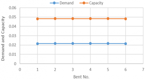
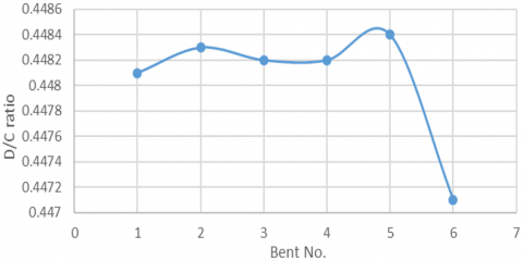
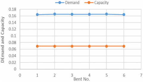
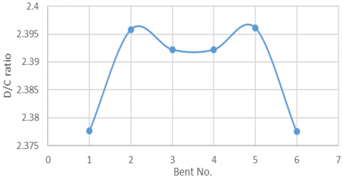
To prevent failure, the demand to capacity ratio must be less than or at least about one. Increasing the cross section of structural elements, decreasing loads, replacing the material to increase strength, or enhancing the qualities of building materials are some ways to do this. Tables 3 and 4, Figures 11-14 list and show the magnitudes of demand, capacity, and D/C ratio in transverse direction (Y) and longitudinal direction (X) respectively on the horizontal plan of bridge structure. For transverse direction (Y) which represents cross section of bridge, the magnitudes of D/C ratio are near for each bent and the maximum value is equal to 0.4484 within bent No. 5 which is lower than 1, indicating that the capacity of bents are more than the demand and the bents can be resistance the seismic effect in transvers direction. But in longitudinal direction of bridge line (X), the D/C ratio for all bents is near and equal to 2.396 as maximum value within bent No. 5 which much more than 1, indicating that the demand is more than capacity of bridge bents and they can’t resist the earthquake lateral load. Therefore, the bridge piers will lead to cracked and destroy due to action of seismic in the longitudinal of bridge length. Therefore, bridge piers will be within plastic area after design yielding point.
Table 3. Demand to capacity ratio for bridge supports in transvers direction (Y)
|
No. of Bent |
Demand (D) |
Capacity (C) |
D/C Ratio |
|
1 |
0.021582 |
0.048168 |
0.4481 |
|
2 |
0.021626 |
0.048241 |
0.4483 |
|
3 |
0.021623 |
0.048241 |
0.4482 |
|
4 |
0.021623 |
0.048241 |
0.4482 |
|
5 |
0.021629 |
0.048241 |
0.4484 |
|
6 |
0.021532 |
0.048161 |
0.4471 |
Table 4. Demand to capacity ratio for bridge supports in longitudinal direction (X)
|
No. of Bent |
Demand (D) |
Capacity (C) |
D/C Ratio |
|
1 |
0.163984 |
0.068967 |
2.3777 |
|
2 |
0.165472 |
0.069066 |
2.3958 |
|
3 |
0.165218 |
0.069066 |
2.3922 |
|
4 |
0.165218 |
0.069066 |
2.3922 |
|
5 |
0.165491 |
0.069066 |
2.3961 |
|
6 |
0.163962 |
0.068963 |
2.3775 |
Figure 11. Demand and capacity percent of bridge bents of precast I-girder bridge in Y direction
Figure 12. D/C ratio of bridge bents of precast I-girder bridge
Figure 13. Demand and capacity percent of bridge bents of precast I-girder bridge in X direction
Figure 14. D/C ratio of bridge bents of precast I-girder bridge in X direction
According to the results of seismic analysis of precast prestressed I-girder bridge structure, the seismic resistance of bridge bents is not enough to resist the lateral horizontal action of earthquake and the stiffness and elasticity of bridge bents need to improve because of the bridge bents arrived to the plastic area and the damages will appear on the bents structure under effects of earthquake action. Therefore, this study suggests to improve the structural performance and seismic resistance of bridge bents by increasing the diameter of bridge piers with adding more steel reinforcement. According to economical state and researcher's experts, this study selects three types of piers diameters as a strengthening process. The first diameter is 1.6 m (20 cm over 1.2 m), the second diameter is 1.8 m (40 cm over 1.2 m), and the third diameter is 2 m (60 cm over 1.2 m). This process can be done by adopting steel reinforcement plant with old pier structure and then cast high performance concrete (c>65 MPa). To compare the results of seismic analysis methods for bridge bents which have new diameters with original diameter of piers (D=1.2 m), this study will analyze the bridge structure due to earthquake action by using three piers diameters which are 1.6 m, 1.8 m, and 2 m. The results of modal method, D/C ratio, and pushover method will be compared then recommending the optimum diameter which uses for piers to resist the action of earthquake.
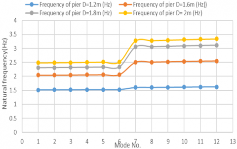
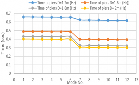
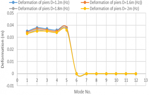
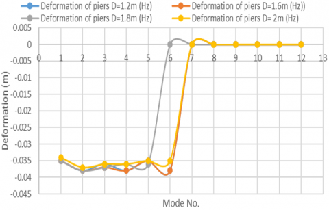
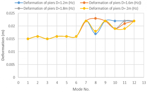
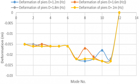
Table 5 lists the values of natural frequency for different piers diameters. Figure 15 shows the natural frequency of bridge structure with piers diameters 1.2 m, 1.6 m, 1.8 m, and 2 m. it can be seen that when the piers diameter is increased, the natural frequency will have increased because of the bearing capacity, elasticity, stiffness, and structural performance will be improved and enough to resist the external loads. Table 6 and Figure 16 list and show modal time of bridge structure with piers diameters 1.2 m, 1.6 m, 1.8 m, and 2 m. For transverse direction, the maximum positive and is 0.038 m with piers diameter 1.2 m in mode No. 2, decreasing to 0.033 m with diameter 2 m in mode No. 1. Also, the negative deformation is decreased in transverse direction from -0.038 m to -0.034. Table 7, Table 8, Figure 17, and Figure 18 list modal positive and negative deformation in Y direction of bridge bents with piers diameters 1.2 m, 1.6 m, 1.8 m, and 2 m. For longitudinal direction, the positive value of deformation decreased from 0.022 m to 0.015 m within piers diameter 1.2 m and 2 m respectively, but the negative deformation decreased from -0.023 m within pier diameter 1.2 m to -0.015 m within diameter 2 m. In general, the deformation of bridge bents is decreased with increasing of piers diameter. Table 9, Figure 19, Table 10, and Figure 20 list and explain the modal positive and negative deformation in X direction of bridge bents with piers diameters 1.2 m, 1.6 m, 1.8 m, and 2 m.
Table 5. Natural frequency of bridge structure with piers diameters 1.2 m, 1.6 m, 1.8 m, and 2 m
|
Mode No. |
Frequency of Pier D=1.2 m (Hz) |
Frequency of Pier D=1.6 m (Hz) |
Frequency of Pier D=1.8 m (Hz) |
Frequency of Pier D=2 m (Hz) |
|
1 |
1.5163 |
2.0435 |
2.3108 |
2.4844 |
|
2 |
1.5176 |
2.0463 |
2.3143 |
2.4883 |
|
3 |
1.5199 |
2.0509 |
2.3202 |
2.4950 |
|
4 |
1.5225 |
2.0563 |
2.3272 |
2.5031 |
|
5 |
1.5250 |
2.0613 |
2.3339 |
2.5107 |
|
6 |
1.5267 |
2.0649 |
2.3386 |
2.5161 |
|
7 |
1.5994 |
2.5018 |
3.0510 |
3.2710 |
|
8 |
1.6035 |
2.5091 |
3.0604 |
3.2815 |
|
9 |
1.6093 |
2.5194 |
3.0742 |
3.2968 |
|
10 |
1.6157 |
2.5308 |
3.0896 |
3.3142 |
|
11 |
1.6214 |
2.5408 |
3.1037 |
3.3302 |
|
12 |
1.6252 |
2.5476 |
3.1135 |
3.3415 |
|
Average |
1.5668 |
2.2893 |
2.7031 |
2.9027 |
Figure 15. Natural frequency of bridge structure with piers diameters 1.2 m, 1.6 m, 1.8 m, and 2 m
Table 6. Modal time of bridge structure with piers diameters 1.2 m, 1.6 m, 1.8 m, and 2 m
|
Mode No. |
Time of Piers D=1.2 m (Hz) |
Time of Piers D=1.6 m (Hz) |
Time of Piers D=1.8 m (Hz) |
Time of Piers D=2 m (Hz) |
|
1 |
0.659 |
0.489 |
0.432 |
0.402 |
|
2 |
0.658 |
0.488 |
0.432 |
0.401 |
|
3 |
0.657 |
0.487 |
0.430 |
0.400 |
|
4 |
0.656 |
0.486 |
0.429 |
0.399 |
|
5 |
0.655 |
0.485 |
0.428 |
0.398 |
|
6 |
0.654 |
0.484 |
0.427 |
0.397 |
|
7 |
0.625 |
0.399 |
0.327 |
0.305 |
|
8 |
0.623 |
0.398 |
0.326 |
0.304 |
|
9 |
0.621 |
0.396 |
0.325 |
0.303 |
|
10 |
0.618 |
0.395 |
0.323 |
0.301 |
|
11 |
0.616 |
0.393 |
0.322 |
0.300 |
|
12 |
0.615 |
0.392 |
0.321 |
0.299 |
Figure 16. Modal time of bridge structure with piers diameters 1.2 m, 1.6 m, 1.8 m, and 2 m
Table 7. Modal Positive deformation in Y direction of bridge bents with piers diameters 1.2 m, 1.6 m, 1.8 m, and 2 m
|
Mode No. |
Deformed of Piers D=1.2 m |
Deformed of Piers D=1.6 m |
Deformed of Piers D=1.8 m |
Deformed of Piers D=2 m |
|
1 |
0.035 |
0.034 |
0.033 |
0.033 |
|
2 |
0.038 |
0.037 |
0.036 |
0.035 |
|
3 |
0.037 |
0.036 |
0.035 |
0.035 |
|
4 |
0.036 |
0.035 |
0.034 |
0.034 |
|
5 |
0.038 |
0.038 |
0.037 |
0.036 |
|
6 |
0 |
0 |
0 |
0 |
|
7 |
0 |
0 |
0 |
0 |
|
8 |
0 |
0 |
0 |
0 |
|
9 |
0 |
0 |
0 |
0 |
|
10 |
0 |
0 |
0 |
0 |
|
11 |
0 |
0 |
0 |
0 |
|
12 |
0 |
0 |
0 |
0 |
Figure 17. Modal Positive deformation in Y direction of bridge bents with piers diameters 1.2 m, 1.6 m, 1.8 m, and 2 m
Table 8. Modal negative deformation in Y direction of bridge bents with piers diameters 1.2 m, 1.6 m, 1.8 m, and 2 m
|
Mode No. |
Deformed of Piers D=1.2 m |
Deformed of Piers D=1.6 m |
Deformed of Piers D=1.8 m |
Deformed of Piers D=2 m |
|
1 |
-0.035 |
-0.035 |
-0.035 |
-0.034 |
|
2 |
-0.038 |
-0.038 |
-0.038 |
-0.037 |
|
3 |
-0.036 |
-0.037 |
-0.037 |
-0.036 |
|
4 |
-0.038 |
-0.038 |
-0.036 |
-0.036 |
|
5 |
-0.035 |
-0.035 |
-0.036 |
-0.035 |
|
6 |
-0.038 |
-0.038 |
0 |
-0.035 |
|
7 |
0 |
0 |
0 |
0 |
|
8 |
0 |
0 |
0 |
0 |
|
9 |
0 |
0 |
0 |
0 |
|
10 |
0 |
0 |
0 |
0 |
|
11 |
0 |
0 |
0 |
0 |
|
12 |
0 |
0 |
0 |
0 |
Figure 18. Modal negative deformation in Y direction of bridge bents with piers diameters 1.2 m, 1.6 m, 1.8 m, and 2 m
Figure 19. Modal positive deformation in X direction of bridge bents with piers diameters 1.2 m, 1.6 m, 1.8 m, and 2 m
Table 9. Modal positive deformation in X direction of bridge bents with piers diameters 1.2 m, 1.6 m, 1.8 m, and 2 m
|
Mode No. |
Deformed of Piers D=1.2 m |
Deformed of Piers D=1.6 m |
Deformed of Piers D=1.8 m |
Deformed of Piers D=2 m |
|
1 |
0.015 |
0.015 |
0.015 |
0.015 |
|
2 |
0.016 |
0.016 |
0.016 |
0.016 |
|
3 |
0.015 |
0.015 |
0.015 |
0.015 |
|
4 |
0.016 |
0.016 |
0.016 |
0.016 |
|
5 |
0.016 |
0.016 |
0.016 |
0.016 |
|
6 |
0.016 |
0.016 |
0.016 |
0.016 |
|
7 |
0.022 |
0.022 |
0.022 |
0.022 |
|
8 |
0.017 |
0.023 |
0.018 |
0.018 |
|
9 |
0.022 |
0.022 |
0.022 |
0.022 |
|
10 |
0.022 |
0.019 |
0.019 |
0.019 |
|
11 |
0.022 |
0.021 |
0.022 |
0.019 |
|
12 |
0.022 |
0.022 |
0.022 |
0.022 |
Table 10. Modal negative deformation in X direction of bridge bents with piers diameters 1.2 m, 1.6 m, 1.8 m, and 2 m
|
Mode No. |
Deformed of Piers D=1.2 m |
Deformed of Piers D=1.6 m |
Deformed of Piers D=1.8 m |
Deformed of Piers D=2 m |
|
1 |
-0.015 |
-0.015 |
-0.015 |
-0.015 |
|
2 |
-0.016 |
-0.016 |
-0.015 |
-0.016 |
|
3 |
-0.015 |
-0.015 |
-0.016 |
-0.016 |
|
4 |
-0.016 |
-0.016 |
-0.016 |
-0.016 |
|
5 |
-0.016 |
-0.016 |
-0.016 |
-0.016 |
|
6 |
-0.016 |
-0.016 |
-0.016 |
-0.016 |
|
7 |
-0.022 |
-0.022 |
-0.022 |
-0.022 |
|
8 |
-0.023 |
-0.017 |
-0.022 |
-0.022 |
|
9 |
-0.022 |
-0.021 |
-0.022 |
-0.022 |
|
10 |
-0.018 |
-0.023 |
-0.023 |
-0.023 |
|
11 |
-0.022 |
-0.022 |
-0.022 |
-0.023 |
|
12 |
0 |
0 |
0 |
0 |
Figure 20. Modal negative deformation in X direction of bridge bents with piers diameters 1.2 m, 1.6 m, 1.8 m, and 2 m
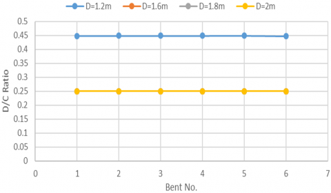
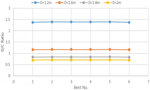
The thickening of piers size is important and has effective influence on the increasing of bridge bent resistant to the effects of earthquake action in horizontal plan. The results of demand-capacity analysis showed that demand to capacity ratio in transverse direction decreased from 0.448 within pier diameter 1.2 m to 0.25 within pier diameter 2 m. Figure 21 illustrates demand to capacity ratio in Y direction of bridge bents with piers diameters 1.2 m, 1.6 m, 1.8 m, and 2 m. For longitudinal direction, the magnitudes of demand to capacity ratio are decreased with increasing the piers diameter and the maximum value decreased from 2.377 to 0.710, lowering the factor 1. Indicating that the bridge bent will have enough capacity to resist the demand. Figure 22 explains the demand to capacity ratio in X direction of bridge bents with piers diameters 1.2 m, 1.6 m, 1.8 m, and 2 m.
Figure 21. Demand to capacity ratio in Y direction of bridge bents with piers diameters 1.2 m, 1.6 m, 1.8 m, and 2 m
Figure 22. Demand to capacity ratio in X direction of bridge bents with piers diameters 1.2 m, 1.6 m, 1.8 m, and 2 m
The main conclusions of this research are:
[1] Hussam, A., Ali, F. (2020). Mathematical assessment of vehicle types and loads influences on the structural performance parameters of concrete and steel bridges. Journal of Engineering Science and Technology (JESTEC), 15(2): 1254-1266.
[2] Meshrama, S., Ramtekeb, P. (2015). Effect of vehicle velocity on the dynamic amplification factor for a simply supported T-beam bridge. International Journal of Innovative and Emerging Research in Engineering, 2(5): 102-108.
[3] Ali, F. (2021). Analysis the effect of super-elevation on static and dynamic properties of horizontal curved concrete bridge by finite element. Journal of Engineering Science and Technology, 16(5): 3669-3686.
[4] Mary, D., John, B., Anagha, S. (2012). Continuous prestressed concrete girder bridges. Vol. 1: Literature review and preliminary designs. Texas Department of Transportation and the Federal Highway Administration, Texas Transportation Institute, Texas.
[5] Ali, N., Wang, Z. (2013). Finite element and experimental analysis and evaluation of static and dynamic responses of oblique pre-stressed concrete box girder bridge. Research Journal of Applied Sciences, Engineering and Technology, 6(19): 3642-3657. https://doi.org/10.19026/rjaset.6.3572
[6] Bridge and Structure Inspection Program Manual. (2017). Bridge type selection, Minnesota Department of Transportation, State of Minnesota.
[7] Abdullah, F.W., Aldhalemi, A.A., Naser, A.F., Jaaz, H.A.G. (2024). Field damage inspection and structural performance assessment of precast prestressed concrete I-girder bridge by adopting static analysis. AIP Conference Proceedings, 3092: 060018. https://doi.org/10.1063/5.0199598
[8] Mohan, A. (2017). The structural behavior of horizontally curved pre-stressed concrete box girder bridges. Doctoral dissertation, School of Computing, Science and Engineering University of Salford, United Kingdom.
[9] Naser, A.F., Zonglin, W. (2011). Damage investigation, strengthening, and repair of Jilin highway double-curved arch concrete bridge in China. Procedia Engineering, 14: 2294-2300. https://doi.org/10.1016/j.proeng.2011.07.289
[10] Al-Rifaie, W., Kareem, A. (1986). Bridges. Building and Construction Engineering Department, University of Technology, Baghdad, Iraq.
[11] Huda, H., Ali, F., Lihui, Q. (2024). Appearance inspection and finite element analysis of posttension concrete horizontal curved box girder bridge: Static and dynamic analysis. Mathematical Modelling of Engineering Problems, 11(10): 2606-2614. https://doi.org/10.18280/mmep.111002
[12] Washington State Bridge Inspection Manual. (2002). Bridge Record, Chapter Six, USA, pp. 1-6.
[13] Naser, A.F. (2018). Optimum design of vertical steel tendons profile layout of post-tensioning concrete bridges: FEM static analysis. ARPN Journal of Engineering and Applied Sciences, 13(23): 9244-9256.
[14] Naser, A.F., Mohammed, H.A., Mohammed, A.A. (2022). Flexure and shear load rating evaluation of composite bridge superstructure under effect of different trucks load types. Materials Today: Proceedings, 57: 398-407. https://doi.org/10.1016/j.matpr.2021.12.268
[15] Agarwal, P., Pal, P., Kumar Mehta, P. (2022). Box-girder bridges-modelling and analysis. International Journal for Engineering Modelling, 35(1): 19-42. https://doi.org/10.31534/engmod.2022.1.ri.02m
[16] Arthur, H. (1987). Design of Pre-Stressed Concrete. Second Edition, Wiley, New York, USA. p. 592.
[17] PCI. (1968). Fundamentals of Pre-Stressed Concrete Design. Second Edition, Pre-Stressed Concrete Institute, Chicago, USA.
[18] Naser, A.F., Zonglin, W. (2010). Strengthening of Jiamusi prestressed concrete highway bridge by using external posttensioning technology in China. ARPN Journal of Engineering and Applied Sciences, 5(11): 60-69.
[19] Setiati, R. (2020). Inspection and evaluation of bridge structures for earthquakes risk. IOP Conference Series: Materials Science and Engineering, 930: 012032. https://doi.org/10.1088/1757-899X/930/1/012032
[20] Naser, A.F., Wang, Z.L. (2011). Damage monitoring and field analysis of dynamic responses of ha Shuang prestressed concrete box girder oblique bridge before strengthening. Advanced Materials Research, 255: 1102-1106. https://doi.org/10.4028/www.scientific.net/AMR.255-260.1102
[21] Bindra, S., Bindra, K. (1980). Elements of Bridge Tunnel and Railway Engineering. Dhanpat Rai and Sons, Delhi and Jullundur, India.
[22] Naser, A.F., Wang, Z.L. (2011). Field damage inspection and static load test analysis of Jiamusi highway prestressed concrete bridge in China. Advanced Materials Research, 163: 1147-1156. https://doi.org/10.4028/www.scientific.net/AMR.163-167.1147
[23] Manaf, A. (2000). Defining standard of periodic bridge maintenance activities in Iraq by adopting expert system technology. Building and Construction Engineering Department in Partial Fulfillment of the Requirements, Degree of Master of Sciences in Civil Engineering, University of Technology.
[24] Naser, A.F., Zonglin, W. (2011). Damage inspection and performance evaluation of Jilin highway double-curved arch concrete bridge in China. Structural Engineering and Mechanics: An International Journal, 39(4): 521-539. https://doi.org/10.12989/sem.2011.39.4.521
[25] Abudayyeh, O., Al Bataineh, M., Abdel-Qader, I. (2004). An imaging data model for concrete bridge inspection. Advances in Engineering Software, 35(8-9): 473-480. https://doi.org/10.1016/j.advengsoft.2004.06.010
[26] Vlašić, A., Srbić, M., Skokandić, D., Mandić Ivanković, A. (2022). Post-earthquake rapid damage assessment of road bridges in Glina county. Buildings, 12(1): 1-42. https://doi.org/10.3390/buildings12010042
[27] Connor, R.J., Dexter, R.J., Mahmoud, H. (2005). Inspection and management of bridges with fracture-critical details: A synthesis of highway practice. Transportation Research Board.
[28] Naser, E. (2005). Repair and strengthening of reinforced concrete structure. RV Anderson Associated Limited, Toronto, Canada.
[29] Hugenschmidt, F. (1981). Strengthening of existing concrete structures with bonded reinforcements. EMPA, Switzerland.
[30] Naser, A.F., Wang, Z. (2012). Experimental monitoring of the strengthening construction of a segmental box girder bridge and field testing of external prestressing tendons anchorage. Frontiers of Structural and Civil Engineering, 6: 308-320. https://doi.org/10.1007/s11709-012-0140-3
[31] Daly, A.F., Witarnawan, W. (1997). Strengthening of bridges using external post-tensioning. In Conference of eastern Asia society for transportation studies, Seoul, Korea.
[32] Naser, A.F., Wang, Z.L. (2011). Experimental analysis and performance evaluation of Fu Feng highway prestressed concrete bridge after strengthening in China. Advanced Materials Research, 189: 2346-2352. https://doi.org/10.4028/www.scientific.net/AMR.189-193.2346
[33] Wang, H.L., Jin, W.L., Cleland, D.J., Zhang, A.H. (2009). Strengthening an in-service reinforcement concrete bridge with prestressed CFRP bar. Journal of Zhejiang University-Science A, 10(5): 635-644. https://doi.org/10.1631/jzus.A0820836
[34] Wood, J. (2015). Earthquake design of bridges with integral abutments. In Proceeding of 6th International Conference on Earthquake Geotechnical Engineering, Christchurch, New Zealand.
[35] Shobhit, G., Sandeep, G. (2021). Seismic effects on different structural members. International Journal for Research in Applied Science & Engineering Technology, 9(VII): 1481-1485. https://doi.org/10.22214/ijraset.2021.36589
[36] Siqueira, G.H., Tavares, D.H., Paultre, P., Padgett, J.E. (2014). Performance evaluation of natural rubber seismic isolators as a retrofit measure for typical multi-span concrete bridges in eastern Canada. Engineering Structures, 74: 300-310. https://doi.org/10.1016/j.engstruct.2014.03.009
[37] Caltrans. (1999). Guidelines for generation of response-spectrum-compatible rock motion time history for application to Caltrans toll bridge Seismic retrofit projects. Caltrans Seismic Advisory Board, California Department of Transportation, Sacramento, CA.
[38] Duan, L., Reno, M. (1999). Performance-based seismic design criteria for bridges. In Structural Engineering Handbook. Boca Raton: CRC Press LLC.
[39] Sonawane, M., Dubey, S., Deodhar, S. (2013). An analytical approach to demand-capacity method. International Journal of Advanced Technology in Civil Engineering, 2(1): 17-23.
[40] Kenneth, T., Yahya, C. (2001). Capacity-demand index relationships for performance based seismic design. Structural Engineering Research Report, Report #NDSE-01-02, Department of Civil Engineering and Geological Sciences University of Notre Dame, Notre Dame, Indiana, USA.
[41] Jaaz, H.A.G., Naser, A.F., Mohammed, H.A., Mohammed, A.A. (2021). Earthquake resistance optimization and evaluation of bridge piers structural form and dimensions based on demand to capacity ratio and yielding points of force-displacement. Mathematical Modelling of Engineering Problems, 8(6): 945-954. https://doi.org/10.18280/mmep.080614
[42] Hasani, H., Freddi, F. (2023). Operational modal analysis on bridges: A comprehensive review. Infrastructures, 8(12): 172. https://doi.org/10.3390/infrastructures8120172.0
[43] Fragiadakis, M. (2013). Response spectrum analysis of structures subjected to seismic actions. In Encyclopedia of Earthquake Engineering. Springer, Berlin, pp. 1-18. https://doi.org/10.1007/978-3-642-36197-5_133-1
[44] Naser, A., Mohammed, H.A., Mohammed, A.A. (2021). Seismic design assessment of bridge piers location effect on the structural capacity of supports under earthquake action. International Journal of Safety and Security Engineering, 11(2): 143-153. https://doi.org/10.18280/ijsse.110203