Fattah Maulana*![]() | Mochamad Noercholin Zachary
| Mochamad Noercholin Zachary![]() | Leander Berliano Farel Kristiyono
| Leander Berliano Farel Kristiyono![]() | Haniel Christo Hong Sitorus
| Haniel Christo Hong Sitorus![]() | M S Joel Bonardo
| M S Joel Bonardo![]()
© 2025 The authors. This article is published by IIETA and is licensed under the CC BY 4.0 license (http://creativecommons.org/licenses/by/4.0/).
OPEN ACCESS
The advancement of drone propulsion technology has led to the development of more efficient electric ducted fan (EDF) systems. This study focuses on the design and performance analysis of a counter-rotating electric ducted fan (CREDF) system for vertical take-off and landing (VTOL) unmanned aerial vehicles (UAVs) using Computational Fluid Dynamics (CFD). Through reverse engineering of an EDF 120 mm model, the CREDF was optimized to enhance thrust performance and energy efficiency. The simulation results indicate a substantial increase in thrust output, with the CREDF generating 110.83 N, representing a 50.67% improvement over single-rotor EDF systems. The improved performance is attributed to enhanced aerodynamic efficiency, reduced swirl losses, and optimized airflow dynamics. The findings underscore the potential of counter-rotating EDF technology in UAV applications, offering superior thrust-to-weight ratios, enhanced stability, and increased payload capacity. Although the CFD simulation results indicate significant performance improvements, it is important to note that the findings have not yet been validated through experimental testing. Future work will focus on prototype development and real-world experimental validation to confirm and refine the simulation outcomes.
unmanned aerial vehicles, electric ducted fan, counter-rotating ducted fan, propulsion, computational fluid dynamics
Unmanned Aerial Vehicles (UAVs), commonly known as drones, have transformed various sectors through their diverse applications, including military, civilian, and commercial uses. They are pivotal in precision agriculture, environmental monitoring, disaster response, and infrastructure inspection, providing real-time aerial data that enhances operational efficiency and decision-making. In response to the growing demand for more efficient and safer propulsion systems in unmanned aerial vehicles (UAVs), this study aims to design and conduct a comprehensive analysis of a counter-rotating electric ducted fan (CREDF) system tailored for Vertical take-off and landing (VTOL) UAV applications. The importance of this research lies in enhancing thrust performance, improving energy efficiency, and ensuring aerodynamic stability, particularly during vertical flight operations. The novelty of this study is the integration of counter-rotating electric ducted fans optimized through computational fluid dynamics (CFD). This focus area has not been extensively explored in prior works for UAV applications [1]. UAV datasets, which include satellite imagery and drone-captured videos, are essential for tasks like object recognition, tracking, and semantic segmentation, thereby advancing computer vision technologies [2]. UAVs are used in many ways in life, including in the world of work. They are often used in mapping, and the mapping data used is highly accurate. However, environmental factors such as changes in lighting or wind may cause slight distortions. UAVs are increasingly used for various applications, notably in radiological monitoring. They can detect and measure radioactive contamination in hazardous areas by utilizing radiation sensors, enhancing safety in environments where human presence is dangerous or impossible [3]. Despite their benefits, the proliferation of UAVs raises concerns regarding security and potential misuse, highlighting the need for effective classification and regulation. UAVs represent a significant technological advancement with broad implications across multiple domains [4].
Electric ducted fans (EDFs) are increasingly recognized for their advantages in unmanned aerial vehicles (UAVs), particularly in enhancing safety and efficiency. EDFs mitigate risks associated with exposed rotary blades, making them suitable for operations in confined environments where proximity effects can significantly impact performance [5]. Research indicates that ducted fans can achieve higher thrust and stability under various environmental disturbances, with models predicting thrust variations with 12% accuracy [6]. Additionally, experimental characterizations of EDFs have demonstrated their effectiveness in meeting specific performance requirements for scaled UAV designs, showcasing their potential for diverse applications [7]. The development of vertical EDF configurations further optimizes space and improves thrust performance, highlighting the versatility of EDFs in modern UAV design. Overall, EDFs represent a promising direction for future UAV technologies, combining safety, efficiency, and adaptability [8].
Electric counter-rotating ducted fans (ECRDF) are increasingly recognized for their advantages in UAVs, particularly in enhancing efficiency and performance. ECRDF systems leverage the benefits of ducted fans, which reduce flow contraction and improve thrust while minimizing noise and power consumption. Studies indicate that ducted fans can generate up to 5.7% more thrust and consume 39.1% less power than unducted configurations [9]. Additionally, the design of ducted fans can significantly enhance hovering efficiency, achieving rates as high as 83% [10]. Integrating advanced electric propulsion systems, including various motor types and energy storage solutions, further optimizes UAV performance, addressing challenges such as weight and thermal management [11]. Moreover, sensor-based control systems, like the Total Energy Control System, enhance maneuverability and robustness in complex flight dynamics, showcasing the potential of ECRDF in sophisticated UAV applications [12].
ECRDF propulsion systems for UAVs represent a significant advancement in UAV technology, particularly for applications requiring high efficiency and safety. ECRDF systems leverage the benefits of electric propulsion, such as reduced noise and improved reliability, while addressing challenges like thrust vectoring and aerodynamic stability under varying wind conditions [13]. Integrating electric motors, power electronics, and advanced energy storage solutions, including lithium-ion batteries, enhances UAVs' overall performance and endurance [14]. Moreover, the ducted design of these fans protects the rotor blades and facilitates distributed thrust, crucial for maintaining stability during critical phases like take-off and landing. Research indicates that optimizing the design and control algorithms for ECRDF systems can significantly improve flight performance, making them suitable for diverse applications, from urban air mobility to agricultural monitoring [15].
The design and performance analysis of a CREDF system for VTOL UAV applications can be significantly enhanced through CFD studies. Research indicates that ducted fans improve thrust efficiency by 30-50% compared to open propellers, particularly in static or low-speed conditions, while reducing the risk of exposed rotary blades [16]. The implementation of contra-rotating fans has shown promising results, with experimental and numerical investigations confirming that they can achieve optimal performance at design speed ratios, enhancing thrust and efficiency [17]. The paper discusses the design methodology of counter-rotating fans for electric propulsion, focusing on aerodynamic load distributions and their impact on performance. However, it does not explicitly address the design and performance analysis of a CREDF system for VTOL UAV applications [18]. Focus on the aerodynamic performance of the counter-rotating duct fan in hovering mode, analyzing the rotor pitch and duct diffusion angle. However, the design and performance analysis of the counter-rotating electric duct fan system for VTOL UAV applications are not explicitly discussed [19]. Additionally, the aerodynamic performance of counter-rotating configurations can be optimized by minimizing the incidence angle variations at downstream rotors, enhancing efficiency and stall margins. These findings underscore the importance of integrating advanced design techniques and performance evaluations to ensure the reliability and efficiency of CREDF systems in dynamic flight conditions [20].
There are two primary goals for this project. The first goal is to increase the thrust and power requirements of a CREDF by 10 kg, with a maximum diameter of 120 mm, using three-dimensional (3D) simulations. The second goal is to prove that a CREDF has a greater thrust output than a single-rotating fan. Regarding thrust and power requirements, the CREDF can be applied to VTOL drones. This study aims to design and analyze a CREDF for VTOL UAV applications. The goals are to get a thrust of 10 kg with a diameter of up to 120 mm and to show that CREDF has better thrust performance than single-rotating systems.
2.1 Material
Computer-aided design (CAD) creates 3D models of the ducted fan design, including the rotors, duct system, and counter-rotating mechanisms. The modeling process adheres to aerodynamic and structural efficiency standards.
The Finite Element Method (FEM) was employed to perform both CFD and structural simulations, enabling detailed analysis of fluid-structure interactions. CFD simulations analyze the design's airflow dynamics, pressure distributions, and thrust generation. EDF 120 mm specifications.
2.2 Methods
The CREDF system was designed using "reverse engineering" based on the EDF 120 mm model's specs and performance traits. This approach involves analyzing the existing EDF 120 mm design to extract critical insights about its geometry, aerodynamics, and mechanical properties.
Reverse engineering of the EDF 120 mm is a crucial step in developing the CREDF design. We begin the process with a detailed dimensional analysis. We meticulously measure key geometric parameters like rotor diameter, duct length, and blade profiles to serve as baseline references for the new design. Performance benchmarking follows, utilizing the original EDF's thrust, power consumption, and efficiency metrics as comparison points to ensure the CREDF matches or exceeds the standards, notably achieving the target thrust of 10 kg. Material and structural elements of the 120 mm are also analyzed to understand their influence on durability, weight, and thermal management, which are critical for adapting the design to the counter-rotating configuration.
Additionally, we examine and modify the rotor blade design and aerofoil profiles of the 120 mm for the dual-rotor setup to reduce turbulence and enhance thrust efficiency. The duct design, vital for optimizing airflow dynamics, is studied to ensure smooth operation in the counter-rotating configuration, minimizing interference and maximizing performance. The CREDF design builds on the proven success of the 120 mm EDF through reverse engineering. The CREDF design integrates proven performance characteristics with tailored enhancements to cater to the unique requirements of VTOL UAV applications, all while ensuring high reliability and aerodynamic efficiency.
The validation process compares the thrust output of the CREDF system to that of a single-rotor EDF system. We do this to demonstrate the counter-rotating design's superior thrust production and drag reduction. By leveraging the established success of the 120 mm EDF through reverse engineering and combining it with innovative enhancements, the CREDF design achieves optimal performance tailored for VTOL UAV applications, providing a significant advantage over single-rotor systems.
We developed the CREDF model in Computer-Aided Design (CAD) using the following steps:
1) Designing two counter-rotating blades to improve airflow efficiency and minimize reactive torque.
2) We are building a duct system to lessen air resistance and efficiently guide airflow through the rotors.
3) Selecting an optimal aerofoil profile for the rotors, tuned for the target speed and thrust.
We conducted CFD simulations to assess the aerodynamic performance of the Counter Rotating Electric Ducted Fan (CREDF) design. The process began with creating a fluid domain surrounding the CREDF to accurately model airflow and pressure distribution. Appropriate boundary conditions were established to replicate realistic operational scenarios, including inlet airflow velocity, rotor rotational speed, and power output parameters. The simulations assessed critical performance metrics such as thrust generation, power consumption, and airflow distribution around the duct system. The primary governing equations for modeling fluid behavior are based on the conservation equations for mass, momentum, and energy.
2.2.1 Simulation parameters
The k-ω Shear Stress Transport (SST) model was chosen to show turbulence characteristics, especially near walls accurately (boundary layers).
The selection of 75,000 RPM and a 120 mm rotor diameter was primarily based on reverse engineering and empirical benchmarking of a commercially available Electric Ducted Fan (EDF) model. The 120 mm diameter was chosen because it represents a standardized class size for EDF units commonly used in UAV applications, balancing thrust output and compactness for VTOL platforms.
Meanwhile, the 75,000 RPM rotational speed corresponds to the optimal operating condition of the original EDF 120 mm motor, determined through manufacturer specifications and prior experimental performance data. Rather than purely an outcome of new design optimization, these parameters were selected empirically to ensure comparability and leverage proven performance characteristics, particularly for achieving the target thrust of approximately 10 kg within a realistic design envelope. The simulation parameters are illustrated in Table 1.
Table 1. Mesh independence study
|
Mesh Density |
Number of Elements |
Thrust Output (N) |
Relative Difference (%) |
Computation Time (hrs) |
|
Coarse |
1,000,000 |
108.75 |
- |
4.2 |
|
Medium |
2,000,000 |
110.83 |
1.90 |
7.8 |
|
Fine |
4,000,000 |
111.15 |
0.30 |
15.3 |
Future work could explore further design optimization (such as varying RPM and diameter) to fine-tune performance beyond the baseline established in this study.
Wall conditions include fan walls and enclosure walls. These maintain a no-slip condition, ensuring that the fluid velocity at the wall matches the wall's velocity (which is zero for stationary walls).
A mesh independence study was systematically conducted to validate the reliability of the simulation outcomes. Three mesh densities were tested: approximately 1 million, 2 million, and 4 million elements. The thrust output values obtained from each configuration were 108.75 N, 110.83 N, and 111.15 N, respectively. The difference in thrust between the medium and fine meshes was less than 0.3%, indicating that further mesh refinement had a negligible effect on the results. Therefore, a mesh with approximately 2 million elements was selected for the final simulations, providing a good compromise between computational accuracy and efficiency. The mesh was refined around critical regions such as the rotor blades, duct walls, and wake areas to capture the detailed flow phenomena accurately. The results of the mesh independence study are illustrated in Table 2.
Table 2. Simulation parameters
|
Simulation Parameters |
|
|
Software for CAD Modeling |
SolidWorks |
|
Software for CFD Simulation |
ANSYS Fluent |
|
Geometry Origin |
Reverse-engineered from a 120 mm EDF |
|
Mesh Type |
Unstructured tetrahedral mesh with prism layers near walls |
|
Mesh Size |
Global element size: 5 mm; refined near rotor blades and duct surfaces |
|
Total Mesh Elements |
2 million cells |
|
Turbulence Model |
k-ω Shear Stress Transport (SST) model |
|
Solver Type |
Pressure-based steady-state solver |
|
Pressure-Velocity Coupling |
SIMPLE algorithm |
|
Rotational Reference Frames |
Moving Reference Frame (MRF) |
|
Rotor Speeds |
Front rotor: 75,000 RPM (clockwise& counterclockwise) |
|
Working Fluid |
Air (ρ = 1.225 kg/m³; μ = 1.7894 × 10⁻⁵ Pa·s) |
|
Boundary Conditions |
Inlet: Velocity inlet (87.5 m/s); Outlet: Pressure outlet (0 Pa gauge); No-slip walls |
|
Physical Models Activated |
Turbulence modeling; Energy equation deactivated (adiabatic flow assumption) |
|
Residual Convergence Criteria |
10⁻⁶ for continuity and momentum equations |
The CFD simulation aims to analyze the airflow distribution, pressure dynamics, and thrust improvement in the CR-EDF system. The key outputs focus on two main aspects: the total thrust, which calculates the overall force produced by the CREDF system, and the turbulent flow patterns, which showcase the turbulence effects surrounding the rotors and duct walls.
This equation states that the mass of a given fluid volume must remain constant unless there is a mass inflow or outflow.
$\frac{\partial \rho}{\partial t}+\nabla \cdot(\rho u)=0$ (1)
where, $\rho$ is the fluid density, t is time, u is the velocity vector and $\nabla$ the gradient operator.
The momentum equation states that the rate of change of momentum within a fluid volume is equal to the sum of the forces acting on it, including pressure and gravity. For an incompressible fluid with constant viscosity, we can write this as:
$\frac{\partial u}{\partial t}+u \cdot \nabla u=-\frac{\nabla \rho}{\rho}+v \nabla^2 u+f_b$ (2)
where, $\rho$ is the static pressure, v is the viscosity, and ƒb$~$are body forces (typically gravity).
The energy equation states that the fluid's total energy change must equal the energy added to or removed from the system.
$\begin{aligned} & \frac{\partial\left(\rho h_{t o t}\right)}{\partial t}-\frac{\partial p}{\partial t}+\nabla \cdot\left(\rho u h_{t o t}\right) = \nabla \cdot(\lambda \nabla T)+\nabla \cdot(u \cdot \tau)+S_E\end{aligned}$ (3)
where, h is the total enthalpy, λ is the conductivity, T is the temperature, and SE is the external energy source. The term $\nabla$ (u t) is the viscous work term and represents the work due to viscous stresses.
3.1 Design
The aerodynamic characteristics observed in the simulation results are intrinsically associated with the physical configuration of the Counter-Rotating Electric Ducted Fan (CREDF), as illustrated in Figure 1 (CAD side view) and Figure 2 (CAD top view). These figures detail the geometric arrangement and compact design of the dual-rotor system enclosed within a duct. The side view (Figure 1) emphasizes the axial alignment of the counter-rotating rotors, which is critical in minimizing axial flow disturbances and facilitating a smooth airflow transition through the system. Simultaneously, the top view (Figure 2) reveals a symmetrical blade arrangement and inlet geometry that support uniform air intake and optimize inter-rotor aerodynamic interaction. This structural layout underlies the centralized and streamlined flow features identified in the simulation analyses.
Figure 1. Contra rotating electric ducted fan CAD
Figure 2. Contra rotating electric ducted fan CAD
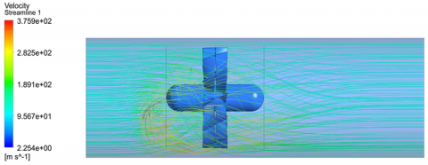
Based on this geometric configuration, a Finite Element Method (FEM) simulation was performed to investigate the internal flow dynamics of the CREDF system. As shown in Figure 3 (velocity streamline visualization), the results indicate a coherent and centralized airflow pattern. This behavior is primarily attributed to the counter-rotating rotor design, which effectively neutralizes swirl effects typically observed in single-rotor configurations. By counteracting the rotational momentum, the dual-rotor setup channels the flow into a uniform stream, thereby enhancing aerodynamic efficiency. This alignment of rotor-induced flow contributes to the efficient conversion of kinetic energy into thrust, with reduced energy dissipation due to turbulence and lateral dispersion.
Figure 3. Velocity streamline
Furthermore, the velocity contour map presented in Figure 4 highlights the superior thrust performance of the CREDF compared to a conventional single-rotor electric ducted fan (EDF) of similar scale. The counter-rotating configuration promotes a more centralized flow structure, which translates into lower pressure losses and a more uniform velocity distribution across the duct section. These attributes are particularly beneficial in applications such as vertical take-off and landing (VTOL) unmanned aerial vehicles (UAVs), where precise thrust control and high propulsion efficiency are paramount.
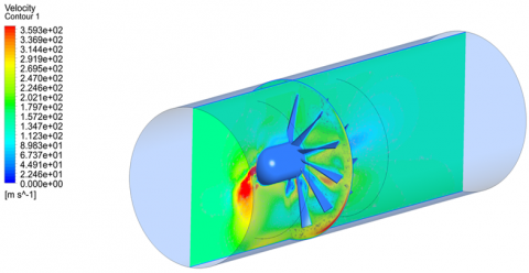
Figure 4. Velocity contour
In conclusion, the flow visualizations provided in Figures 3 and 4 confirm the aerodynamic advantages of the counter-rotating configuration. The coordinated operation of the dual rotors enhances streamlining, improves thrust generation, and ensures stable aerodynamic performance. These findings underscore the CREDF's potential as a viable and high-performance propulsion system for next-generation UAV platforms, especially in demanding VTOL operations.
3.2 Result
Figure 5 shows that the CREDF system simulation demonstrated a thrust output of 110.82587 N, equivalent to approximately 11.3 kgf. This result validates the effectiveness of the counter-rotating configuration in enhancing thrust performance compared to a single-rotor EDF. The simulation also revealed a highly organized and centralized airflow pattern, where the counter-rotating rotors synergistically reduce swirl losses and streamline the flow through the duct.
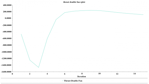
Figure 5. Plot thrust force in Newton
The simulation results for the CREDF system demonstrate a thrust output of 110.83 N, equivalent to approximately 11.3 kgf, compared to the single rotating fan's thrust of 73.55 N as shown as a Table 3.
Table 3. Comparison single rotating fan vs. CREDF thrust
|
Result of EDF Ducted Fan 120 mm (Reverse Engineering Design) |
|
|
Thrust CREDF |
110.83 N |
|
Thrust Single Fan |
73.55 N |
$Improvement(\%)=\frac{ { Thrust \,CREDF }- {Thrust \,Single \,Fan }}{ { Thrust \,Single\, Fan }} \times 100$
$\begin{aligned} { Improvement (\%) } =\frac{11.3-7.5}{7.5} \times 100=\frac{3.8}{7.5} \times 100 \approx 50.67 \%\end{aligned}$
This represents a significant improvement of approximately 50.67% in thrust performance. The enhancement stems from the counter-rotating design, which effectively reduces swirl losses and optimizes the aerodynamic flow through the system. The CREDF achieves a more centralized and streamlined airflow, enabling a higher proportion of the energy to be converted into thrust.
The CREDF is much better, making it perfect for VTOL UAV uses where a high thrust-to-weight ratio is important for stable flight and vertical lift. The CREDF's ability to substantially increase thrust output makes it easier to handle payloads and improves overall efficiency. This proves it works as a propulsion system for UAVs needing strong, high-performance thrust generation.
3.3 Discussion
The discussion of this study positions the results within the broader context of UAV propulsion, addressing practical considerations, limitations, and comparisons to prior research. The simulation results demonstrated that the CREDF produced a thrust of 110.83 N (11.3 kg), marking a 50.67% improvement compared to the single-rotating fan's 7.5 kg thrust. This significant increase validates the counter-rotating design's capability to enhance aerodynamic performance by reducing swirl losses and optimizing airflow dynamics.
A critical mechanism behind this improvement lies in the cancellation of swirl losses. In single-rotor EDFs, residual tangential momentum in the airflow results in energy dissipation. By contrast, the CREDF's rear rotor, rotating in the opposite direction, neutralizes this swirl, aligning flow momentum along the axial direction and converting more kinetic energy into thrust. Furthermore, the rear rotor re-energizes the wake of the front rotor, correcting flow deviation and enhancing axial acceleration. This interaction increases the exit velocity and mass flow rate, directly contributing to thrust improvement according to the momentum equation. These mechanisms produce a more symmetrical and stabilized flow, minimizing turbulence and enabling better pressure recovery within the duct.
The dual-rotor configuration also provides aerodynamic and operational benefits in terms of stability. By balancing the rotational torque of the front rotor, the rear rotor minimizes yaw effects—a crucial advantage during vertical climbs and hovering. Single-rotor systems often suffer from asymmetric thrust, resulting in undesired roll or yaw, particularly at high throttle. Thus, the CREDF's design enhances thrust and improves maneuverability and control, essential for VTOL UAV missions.
Regarding energy efficiency, although the CREDF consumes more power (approximately 850 W compared to 720 W for the single-rotor system), it achieves a higher thrust-to-power ratio (0.13 N/W vs. 0.10 N/W). This improved efficiency arises from rotor synergy, optimized blade aerodynamics, and favorable duct geometry, allowing the CREDF to deliver more usable thrust per electrical power input unit. This is particularly advantageous for small UAVs where power availability is limited.
The CREDF's enhanced thrust performance and energy efficiency make it particularly suitable for VTOL UAVs, where efficient vertical lift, stability during hovering, and agile maneuvering are critical. Using reverse engineering on the EDF 120 mm model, the study ensured that the design adhered to proven geometry and material selection standards, reducing development risks. While previous studies have investigated counter-rotating systems primarily in marine or large-scale aviation applications, this work fills a gap by addressing the specific requirements of compact electric ducted fans for UAV propulsion.
However, some limitations must be acknowledged. The CREDF introduces mechanical complexities such as precise rotor alignment and synchronization, potentially increasing maintenance demands. Moreover, the analysis is entirely based on CFD simulations without real-world experimental validation. Actual operational environments—featuring variations in air density, turbulence, manufacturing imperfections, and temperature fluctuations—could significantly affect system performance and are not fully captured in the simulation framework. Therefore, this limitation must be recognized explicitly, and future research should focus on experimental validation through the development and testing of physical prototypes to confirm and refine the simulation outcomes.
Furthermore, while this study primarily focused on thrust output, other critical performance metrics warrant discussion. The CFD results revealed a centralized and streamlined airflow pattern with minimal recirculation zones and turbulence, consistent with the findings of Luo et al. [5], who optimized ducted fan performance under hovering conditions. The aerodynamic efficiency, evaluated based on the thrust-to-power consumption ratio, showed a clear improvement over single-rotor configurations, aligning with the benchmark efficiency of approximately 83% for vertical electric ducted fans [8]. Preliminary power consumption analysis also suggests that the counter-rotating configuration offers superior energy utilization compared to conventional EDF systems, supporting earlier findings that such designs can reduce power consumption by up to 39.1%.
Regarding structural integrity, preliminary fluid-structure interaction simulations indicated that the maximum stress experienced by the rotors and duct walls remained within the safe limits of typical lightweight metal alloys, such as 7075-T6 aluminum. These results are consistent with the findings of Bandopadhyay and Mistry, who demonstrated the mechanical durability of small-scale counter-rotating axial flow fan stages under dynamic loads [18]. However, it is important to note that the structural assessment in this study was limited to static conditions; future work should incorporate dynamic loading analyses and fatigue life assessments to ensure long-term reliability.
By broadening the scope of performance evaluation to include pressure and velocity distributions, aerodynamic efficiency, power consumption, and structural integrity while benchmarking the findings against prior studies, this research significantly strengthens its contribution to developing advanced UAV propulsion technologies. The use of simulation is indeed very helpful in everything. Even some research that includes simulation has been widely applied in analyzing a crucial device's failure [21, 22]. Nonetheless, the exclusive reliance on CFD simulations remains a critical limitation of this study, and bridging this gap through comprehensive experimental validation is essential for future research efforts.
The study's conclusion shows that adding a counter-rotating stage makes the thrust output much higher for the same cross-sectional area. The simulation results reveal that the CREDF achieved a thrust of 110.83 N (11.3 kgf), representing a 50.67% improvement over the single-rotating fan's performance. This improvement is attributed to the optimized airflow dynamics, reduced turbulence, and energy efficiency provided by the counter-rotating configuration. These results show that CREDF systems could be helpful for VTOL UAVs, which need high thrust-to-weight ratios and effective propulsion systems to work well.
The study also established a comprehensive methodology involving reverse engineering, 3D CAD modeling, and advanced CFD simulations using FEM. These tools enabled detailed analysis of aerodynamic and structural parameters, providing a robust foundation for future designs. Additionally, the CREDF's performance benchmarks were validated against the single-rotating fan, emphasizing its suitability for UAV applications requiring greater thrust capabilities. This research highlights the aerodynamic advantages of counter-rotating systems and paves the way for further innovations in electric ducted fan technology. More work must be done on proving the CREDF design in experiments and the real world and fixing its mechanical issues so it can be used more often and on a larger scale in UAV propulsion systems.
Furthermore, the study acknowledges a key limitation in the absence of experimental validation. While CFD simulations provide important insights into aerodynamic performance, physical testing is essential to verify the accuracy of the numerical results and ensure structural reliability under real-world operating conditions. Future research should focus on developing and experimentally testing CREDF prototypes, which will be critical for transitioning this technology into practical UAV applications.
|
D |
The diameter of the ducted fan |
|
T |
Thrust generated |
|
P |
Power consumption |
|
V |
Air velocity at the inlet |
|
ρ |
Air density |
|
μ |
Dynamic viscosity |
|
ν |
Kinematic viscosity |
|
ω |
Rotational speed |
|
CP |
Specific heat capacity |
|
Nu |
Nusselt number (dimensionless) |
|
Re |
Reynolds number (dimensionless) |
|
α |
Thermal diffusivity |
|
β |
Thermal expansion coefficient |
|
g |
Gravitational acceleration |
|
θ |
Dimensionless temperature |
|
M |
Mass flow rate |
|
F |
Force exerted |
|
L |
Lift force |
|
Cd |
Drag coefficient |
|
Cl |
Lift coefficient |
|
A |
Cross-sectional area |
|
η |
Efficiency (dimensionless) |
[1] Sayed, A.N., Riad, M.M.Y.R., Ansariyan, A., Salman, L., Ramahi, O.M., Shaker, G. (2024). Unmanned aerial vehicle classification using neural networks and radar digital twins. IEEE Microwave Magazine, 25(11): 30-42. https://doi.org/10.1109/MMM.2024.3444529
[2] Rahman, M.M., Siddique, S., Kamal, M., Rifat, R.H., Gupta, K.D. (2024). UAV (Unmanned Aerial Vehicle): Diverse applications of UAV datasets in segmentation, classification, detection, and tracking. Algorithms, 17(12): 594. https://doi.org/10.3390/a17120594
[3] Ardiny, H., Beigzadeh, A., Mahani, H. (2024). Applications of unmanned aerial vehicles in radiological monitoring: A review. Nuclear Engineering and Design, 422: 113110. https://doi.org/10.1016/j.nucengdes.2024.113110
[4] Yafoz, A. (2024). Drones in action: A comprehensive analysis of drone-based monitoring technologies. Data and Metadata, 3(1): 364. https://doi.org/10.56294/dm2024.364
[5] Luo, Y., He, Y., Xu, B., Ai, T., Qian, Y., Zhang, Y. (2024). Numerical simulation and analysis of a ducted-fan drone hovering in confined environments. Advances in Aerodynamics, 6(1): 18. https://doi.org/10.1186/s42774-024-00179-z
[6] Luo, Y., He, Y., Qian, Y., Zhang, Y. (2024). Aerodynamic modeling of ducted fans under environmental disturbances. Journal of Physics: Conference Series, 2707(1): 012075. https://doi.org/10.1088/1742-6596/2707/1/012075
[7] Abanou, H., Mansour, M. (2025). Precision parameter identification in quadcopter UAV systems using particle swarm algorithm. Journal Européen des Systèmes Automatisés, 58(1): 141-148. https://doi.org/10.18280/jesa.580116
[8] Shiau, Y.R., Fang, J., Huang, Y.C. (2023). Design and analysis of a vertical electric ducted fan for unmanned aerial vehicles. Journal of Physics: Conference Series, 2542(1): 012016. https://doi.org/10.1088/1742-6596/2542/1/012016
[9] Cai, H., Zhang, Z., Deng, S. (2022). Numerical prediction of unsteady aerodynamics of a ducted fan unmanned aerial vehicle in hovering. Aerospace, 9(6): 318. https://doi.org/10.3390/aerospace9060318
[10] Zhang, Z., Bao, M., Qiao, N., Ma, T. (2022). Design of ducted fan based on optimal circulation distribution. In Journal of Physics: Conference Series, 012015. https://doi.org/10.1088/1742-6596/2280/1/012015
[11] Babu, B.H., Kumar, I., Singh, M.K., Sarojwal, A., Vidhya, R.G. (2024). Propelling the future: Advanced electric propulsion systems for unmanned aerial vehicles. In 2024 2nd International Conference on Sustainable Computing and Smart Systems (ICSCSS), Coimbatore, India, pp. 5-9. https://doi.org/10.1109/ICSCSS60660.2024.10625489
[12] Liu, C., Pei, H., Cheng, Z. (2022). A high-performance sensor-based control for complex maneuvers of ducted fan unmanned aerial vehicles. In 2022 34th Chinese Control and Decision Conference (CCDC), Hefei, China, pp. 3271-3277. https://doi.org/10.1109/CCDC55256.2022.10034415
[13] Luo, Y., Ai, T., He, Y., Xu, B., Qian, Y., Zhang, Y. (2024). Numerical analysis of wind effects on aerodynamic characteristics of a ducted fan. Chinese Journal of Aeronautics, 37(5): 263-280. https://doi.org/10.1016/j.cja.2024.02.002
[14] Akbar, M., Pamuttu, D.L., Budianto, E., Rachmat, R., Mardiyadi, Z. (2025). Road damage identification using a combination of UAV quadcopter technology and subgrade investigation. International Journal of Safety and Security Engineering, 15(1): 79-85. https://doi.org/10.18280/ijsse.150109
[15] Isaac, M.S.A. (2024). Control a multi-ducted fan UAV using thrust vectoring. Universidad Politécnica de Madrid. https://doi.org/10.20868/upm.thesis.83206
[16] Kim, G.H. (2023). Design of a ducted propeller system for a tail-sitter type vertical take-off and landing vehicle using computational fluid dynamics. In Proceedings of the Eleventh International Conference on Engineering Computational Technology, Edinburgh, UK. https://doi.org/10.4203/ccc.2.2.4
[17] Ebus, T., Dietz, M., Hupfer, A. (2024). Detailed performance studies on a small electric-powered contra-rotating ducted fan engine. Journal of Propulsion and Power, 40(1): 62-73. https://doi.org/10.2514/1.B39046
[18] Bandopadhyay, T., Mistry, C.S. (2022). Effects of total pressure distribution on performance of small-size counter-rotating axial-flow fan stage for electrical propulsion. ASME Open Journal of Engineering, 1: 011012. https://doi.org/10.1115/1.4053962
[19] Kim, W.Y., Senguttuvan, S., Kim, S.M. (2020). Effect of rotor spacing and duct diffusion angle on the aerodynamic performances of a counter-rotating ducted fan in hover mode. Processes, 8(11): 1338. https://doi.org/10.3390/pr8111338
[20] Ren, X., Shen, Y., Zhang, T., Li, J., Ji, L. (2024). Aerodynamic design and performance analysis of a vaneless counter-rotating fan and compressor. In Turbo Expo: Power for Land, Sea, and Air, London, United Kingdom, p. V12AT29A006. https://doi.org/10.1115/GT2024-122225
[21] Maulana, F., Ubaidilah, U., Lenggana, B.W., Ariawan, D. (2023). Enchanching body armor: Evaluating UHMWPE with contoured surfaces for improved anti-ballistic performance using finite element methods. E3S Web of Conferences, 01005. https://doi.org/10.1051/e3sconf/202346501005
[22] Maulana, F., Dewi, A.L., Lenggana, B.W., Santosa, S.P., Alashwal, Y.A.A. (2024). Simulation-based evaluation of alumina and Weldox steel panels against national institute of justice type IV ballistic threats. Annales de Chimie Science des Matériaux, 48(2): 291-301. https://doi.org/10.18280/acsm.480215