Stanislav Maltsev![]() | Ilya Kozunin*
| Ilya Kozunin*![]() | Mikhail Semin
| Mikhail Semin![]() | Lev Levin
| Lev Levin![]()
© 2025 The authors. This article is published by IIETA and is licensed under the CC BY 4.0 license (http://creativecommons.org/licenses/by/4.0/).
OPEN ACCESS
Ensuring effective ventilation in dead-end chambers is crucial for mine safety and efficiency. Traditional auxiliary ventilation systems, using low-power fans and ducts, dominate current practices. However, diffusion-based ventilation offers a viable alternative for dead-end chambers with a small length-to-cross-sectional area ratio. This method, driven by turbulent diffusion from airflow in through-ventilated workings, was first introduced by Voronin but remains underrepresented in regulatory guidance. Existing standards often limit dead-end lengths (e.g., 10 m) for diffusion-based ventilation without considering critical factors like cross-sectional area and air velocity. This study bridges gaps in understanding diffusion-based ventilation, evaluating its feasibility for longer and larger dead-end chambers. We show that dead-end chambers up to 70 meters in length can be ventilated effectively by diffusion-based system alone. An analytical relationship has been developed to estimate gas concentration over time under varying geometric conditions. These results offer a practical framework for assessing gas contamination in dead-end chambers at other mining operations where diffusion-based ventilation is used, contributing to the optimization of mine ventilation strategies and enhancing overall safety.
mine ventilation, auxiliary ventilation systems, diffusion-based ventilation, dead‑end chamber, turbulent diffusion, pollutant removal efficiency
Ensuring the required air supply to all working areas is a key task in mine ventilation [1, 2]. Working areas are located either in open-ended workings, where airflow passes continuously, or in dead-end chambers, where airflow terminates at the face. The ventilation of dead-end chambers presents particular challenges and is of significant interest [3, 4].
Traditionally, the ventilation of dead-end chambers is carried out using auxiliary ventilation systems, which include low-power fans and ventilation ducts leading to the dead end [5, 6]. The main types of auxiliary ventilation are forcing, exhaust, and overlap systems [7].
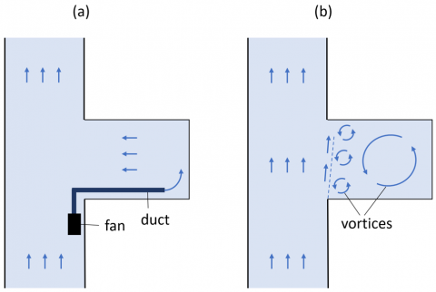
For shorter workings, ventilation may be possible without the use of auxiliary fans. For ex-ample, in Russia, dead-end chambers up to 10 m in length can be ventilated through diffusion. In this case, air exchange in the heading is created by the turbulent influence of the airflow in the adjacent open-ended working with through ventilation. The primary mass transfer mechanism here is turbulent diffusion, which is why this method is often referred to as diffusion-based ventilation [8]. This term was first introduced by Voronin in his pioneering work. By contrast, in systems with ventilation ducts, the dominant mechanism is convective mass transfer (see Figure 1).
Figure 1. Principles of mass transfer in traditional forcing ventilation systems (a) and in diffusion-based ventilation (b) of the dead-end chambers
However, as the length of dead-end chambers increases, the effectiveness of turbulent mixing near the dead-end face decreases. This results in insufficient removal of combustible and toxic gases released from the rock mass and during technological operations [7, 8].
Furthermore, the regulatory limit for diffusion ventilation in dead-end chambers up to 10 m does not consider important parameters such as the cross-sectional area of the heading and the average air velocity in the adjacent open-ended working. These factors significantly affect the efficiency of pollutant removal, especially in large cross-section headings, which may remain effectively ventilated even at lengths exceeding 10 m. Although the ventilation of large cross-section chambers has been addressed in previous studies [9], the specific influence of cross-sectional area on diffusion processes was only examined when using the forced ventilation system. Thus, clarification of the conditions under which diffusion-based ventilation of workings is acceptable is a highly relevant task.
Diffusion-based ventilation has been investigated in several studies. In reference [10], the ventilation of dead-end chambers up to 20 m long and with a cross-sectional area of up to 18 m² via diffusion processes was analyzed. Using a mathematical model, the aerodynamic processes in the dead-end chamber were studied under varying cross-sectional areas and airflow velocities in the adjacent through-ventilated working. Simulations conducted in OpenFOAM identified vortex structure dimensions and flow velocities. It was found that ventilation efficiency largely depends on the width of the dead-end chamber, while height has negligible impact.
In reference [11], the unsteady convective-diffusion equation was additionally solved for dead-end chamber 20 m long and with a cross-sectional area of 25 m². The initial gas concentration ranged from 15 to 25 times the maximum permissible concentration (MPC). The simulation results provided a relationship for estimating ventilation time as a function of heading length, initial gas concentration, and airflow rate. However, this relationship is limited to dead-end chambers up to 20 m long and with gas concentrations not exceeding 25 MPC.
Ventilation of longer dead-end chambers was examined in reference [12], where chambers up to 50 m long and with a cross-sectional area of 132 m² were studied. Enhanced mass exchange in the dead-end chambers was achieved using a booster fan installed in the adjacent through-ventilated workings. The airflow from the booster fan, with a velocity exceeding 20 m/s, intensified turbulent mixing in the dead-end chambers and generated stable vortices within them. This setup ensured sufficient air exchange. Based on the calculated airflow rates, it was concluded that such a ventilation system, with one booster fan capable of ventilating three chambers, can effectively replace polluted air with fresh air.
The use of booster fans is a promising technological solution for ventilating a large number of consecutive blind workings with large cross-sections. The air jet emitted from booster fans, which gradually expands in cross-section, entrains a significant volume of air, enhancing the average airflow velocity and intensifying turbulent diffusion in large cross-section dead-end chambers. In contrast, traditional auxiliary ventilation layouts relying on ventilation ducts become less effective in case of substantial difference between the cross-sectional area of the duct and the dead-end chamber it ventilates—particularly when the latter exceeds 100 m².
Booster fans have been the subject of numerous studies in mine ventilation. Gendrue et al. [13] used CFD modeling to investigate the impact of booster fans on air distribution in a branched section of a mine developed using a room-and-pillar system. The main focus of this work was the investigation of recirculation loops in a network of through-ventilated workings. De Souza and Penner [14] employed CFD modeling to explore the potential use of booster fans in underground levels to create additional pressure. The authors provided guidelines for the proper design and placement of booster fans underground to achieve an economical ventilation system and ensure safe working conditions. A significant number of studies also focus on simulating booster and jet fans in tunnels [15, 16]. However, ventilation of tunnels has specific characteristics that limit the direct application of conclusions of the relevant studies to mining operations.
Existing studies on booster fans primarily focus on workings with through ventilation and rarely address the diffusion-based ventilation of dead-end chambers. Research on the diffusion-based ventilation of dead-end chambers using booster fans primarily concentrates on mass transfer and overlooks the removal of harmful impurities generated during mining operations. Furthermore, the influence of cross-sectional area on the efficiency of impurity removal from dead-end chambers of various lengths has not been analyzed. This study aims to fill these gaps by evaluating the feasibility of ventilating dead-end chambers after blasting operations through diffusion processes. Additionally, it seeks to develop an analytical relationship for estimating the time required for gas concentrations in the heading to reach permissible levels. Determination of analytical dependences of concentration on time is important in order to more deeply understand the physical nature of mass transfer in the face zone of a dead-end chamber. Using these dependencies, we identify the dominant mechanisms of mass transfer in large cross-section dead-end chambers, as well as their intensity. This is done for the first time and holds significant practical importance.
The subject of this study is a gypsum mine located in Russia. Mineral extraction at the mine is conducted using the drilling-and-blasting method. According to the blast work plan, a total of 591.2 kg of explosives is detonated simultaneously in a single chamber, with the excavation area having a cross-sectional area of 132 m². In total, 8 explosions were conducted in 8 separate chambers. Blasting operations generate toxic gases, among which carbon monoxide (CO) is assumed to be the primary harmful component [17-19]. In addition to carbon monoxide, the detonation of the granular ammonite explosives ‘6JV’ also produces nitrogen oxides (NOx) and carbon dioxide (CO₂), although in smaller quantities. Water vapor and hydrogen may also form in trace amounts. It is assumed that no airborne particulate matter is produced during the explosion of explosives. The gas yield of granular ammonite explosives ‘6JV’ is 895 l/kg, as per the technical specifications, although it may vary depending on the mineralogical composition of the surrounding rocks and the conditions of blasting operations.
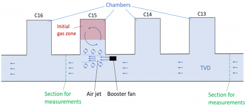
The dead-end chambers, up to 70 meters in length, are ventilated by diffusion. This ventilation occurs due to the interaction of air masses with the high-velocity air jet moving through the transport-ventilation drift (TVD), which operates with through ventilation (see Figure 2). The intensification of mass exchange near the entrances of the dead-end chambers is facilitated by booster fans installed sequentially every five chambers. This "blow-out" effect allows fresh air to gradually enter the dead-end chambers, replacing the contaminated air containing gases generated during blasting operations.
Experimental research was conducted to determine the distribution of airflow velocities and the temporal variations in gas concentrations, specifically carbon monoxide, during the ventilation process of the chambers. In this study, it is assumed that the primary harmful gas is CO, as short-term peak concentration values after blasting operations can reach up to 25 times the MPC, highlighting the need for prioritized control of this particular gas. This research was essential for a large-scale quantitative assessment of the ventilation quality using booster fans. The data obtained were used to parameterize and validate the mathematical model of air and gas transfer in considered mine workings system.
Initially, measurements of the air velocity were taken in the TVD at the fault between chambers C12 and C13 to determine the total airflow entering the system of the mine workings. A total of 936 m³/min of air was measured, corresponding to an air velocity of 0.3 m/s in the TVD with a cross-sectional area of 52 m². For model validation, point measurements of the air velocity were conducted at the fault between chambers C15 and C16, with each measurement statistically processed. Air velocity measurements were made by tracing the section, using a point method with an APR-2M anemometer. The general layout of the workings is shown in Figure 2.
Figure 2. Schematic of the investigated mine section and the locations of measurement points
To measure the concentration of carbon monoxide, a gas analyzer "Draeger X-am 5600" with continuous recording functionality [20] was installed in the TVD between chambers C15 and C16. The gas being analyzed enters the device using the diffusion method of sampling. The analyzed ambient air diffuses through capillaries to the measuring electrode, where an electrochemical reaction occurs. As a result of this reaction, a corresponding constant potential difference arises between the measuring electrode and the additional reference electrode, proportional to the content of the component being determined. According to the technical specifications provided in the instrument's manual, the sensor's relative error limit is no more than 15%, and the measurement range spans from 0 to 2000 ppm. The gas analyzer was installed at the junction between the workings due to the impracticality of placing the device in the dead-end chamber, where blasting operations were being conducted. Prior to installation, the device was synchronized with local time using software and then calibrated in the mine yard under fresh air conditions, where concentrations of toxic and flammable gases were zero. The gas analyzer was installed at 22:19, and measurements were completed at 08:47. Blasting operations in the mine occurred at 23:50, and a few minutes later, ventilation of the study area commenced with the activation of booster fans. No other technological operations were performed during the blasting.
For this study, the ANSYS Fluent module, part of the ANSYS Workbench environment, was used to create a 3D model. This software is widely recognized for its ability to deliver accurate and reliable simulations of fluid flows, as demonstrated by its extensive application in numerous studies in mine ventilation [21, 22].
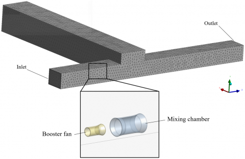
The developed model of the mining section was constructed based on the actual geometric parameters of the mine workings, including surface roughness. The dead-end chamber has a cross-sectional area of 132 m² and a length of 70 meters, while the TVD has a cross-sectional area of 52 m². A VM-6 booster fan was placed in the TVD and equipped with a mixing chamber. The latter is a through pipe with a slightly larger diameter (1.2 m), designed to eject additional air volume and increase the total mass of air in the jet. The primary parameters of the ventilation equipment and its location in the TVD are illustrated in Figure 2.
The computational domain was discretized into tetrahedral finite volumes. The element size was set to 1.1 m on the walls of the mine workings and 0.05 m on the walls of the fan. A prismatic boundary layer was applied to all impermeable walls to enhance accuracy and convergence rate of the iterative procedure. The total mesh consisted of approximately 731,000 finite volumes. Figure 3 presents the overall geometry and computational mesh. The mesh parameters were chosen to satisfy the Y+ condition (30-300) and to ensure solution convergence and independence from the mesh. Different element sizes were also considered for the mesh independence analysis. The results of this analysis are presented in Table 1. The 11 points shown correspond to point values of air velocity along a horizontal path at a distance of 10 meters from the junction with the TVD. Negative values indicate the reverse air movement directed from the dead-end chamber. Results shows that, in general, the velocity field does not change significantly when the size of the tetrahedral cell of the dead-end chamber wall varies (the average mismatch for 11 considered distances is 6.4%. Thus, a mesh with a cell size of 1.1 m on the chamber wall allows for correct modeling of the air flow structure and the transport of impurities in the chamber.
Figure 3. Geometry of the investigated section of the mine and the computational mesh
Table 1. Air velocity values in a dead-end chamber at a distance of 10 meters from the junction with the TVD, during the mesh convergence analysis
|
Distance from the Left Wall (4 m Height) |
Air Velocity (m/s) at Element Size |
||
|
1 m |
1.1 m |
1.2 m |
|
|
1 |
0.353 |
0.345 |
0.344 |
|
2 |
0.154 |
0.139 |
0.139 |
|
3 |
-0.150 |
-0.143 |
-0.137 |
|
4 |
-0.241 |
-0.221 |
-0.234 |
|
5 |
-0.265 |
-0.258 |
-0.238 |
|
6 |
-0.264 |
-0.240 |
-0.243 |
|
7 |
-0.231 |
-0.235 |
-0.238 |
|
8 |
-0.211 |
-0.206 |
-0.222 |
|
9 |
-0.188 |
-0.179 |
-0.198 |
|
10 |
-0.157 |
-0.147 |
-0.167 |
|
11 |
-0.130 |
-0.123 |
-0.134 |
The simulation is performed using a time step of 1 second. The total number of time steps is set to 28800, which corresponds to a total simulation duration of 8 hours (since 28800 seconds equals 8 hours). In addition, the maximum number of iterations is limited to 10, which was necessary to ensure the stability and convergence of the simulation process.
Air distribution calculations were performed based on the incompressible Reynolds-averaged Navier-Stokes equations:
$\frac{\partial \rho}{\partial t}+\nabla \cdot(\rho \mathbf{V})=0$ (1)
$\begin{aligned} & \frac{\partial}{\partial t}(\rho \mathbf{V})+\nabla \cdot(\rho \mathbf{V} \mathbf{V})= -\nabla p+\nabla \cdot\left\{\left(\mu+\mu_t\right)\left[\nabla \mathbf{V}+(\nabla \mathbf{V})^T\right]\right\}+\rho \mathbf{g}\end{aligned}$ (2)
where, t is the time, s; ρ is the air density, kg/m3; V is the air velocity vector, m/s; p is the pressure, Pa; g is the gravity acceleration vector, m/s2; µ is the molecular viscosity, Pa·s; µt is the turbulent viscosity, Pa·s.
The Realizable k-ε turbulence model was used to close the above equations. This model offers significant improvements over the Standard k-ε model. Specifically, the Realizable k-ε model provides more accurate predictions of the dissipation velocity in both flat and round jets and de-livers better predictions for boundary layer characteristics [23-25]. To simulate the distribution of gas impurities, the Mixture model was applied. The carrier phase, representing the first component of the mixture, was air. The second phase in the mine working's atmosphere was carbon monoxide, produced in significant quantities during blasting operations. No additional phases were considered.
The relative velocity of the secondary phase is assumed to be zero. Generation or mass flux of harmful impurities within the domain during the simulation process is absent (i.e., all mass of the harmful impurity is introduced into the system at the initial moment of time, and it exits the computational domain only through the exit zone). In this case, the main equation for the convective transport of air-gas components can be written in the form:
$\frac{\partial}{\partial t}\left(\alpha_p \rho_p\right)+\nabla \cdot\left(\alpha_p \rho_p \mathbf{V}\right)=0$ (3)
where, αp is the concentration of the impurity p, m3/m3; ρp is the density of the impurity p, kg/m3.
To maintain mass balance, the equation is supplemented by the condition that the sum of the concentrations of air and gas impurity is equal to one.
To simulate ventilation in the dead-end chamber, boundary conditions were defined for air velocities within the study area. The performance of the booster fan was specified as an interface boundary condition on the inner surface of the computational domain. This condition was defined as a pressure difference between two surfaces and the airflow rate passing through them. According to the technical documentation for the VM-6 booster fan, with a blade angle of 0°, the boundary condition is expressed numerically by Eq. (4):
$\Delta P=2489+132.5 U-7.19 U^2$ (4)
where, ΔР is the pressure difference, Pa; U is the mean air velocity at the interface, m/s.
The pressure–velocity coupling was handled using the SIMPLE (Semi-Implicit Method for Pressure-Linked Equations) algorithm, which is widely applied for incompressible flow simulations. Convection terms were discretized using the first-order upwind scheme to ensure numerical stability. To enhance accuracy, particularly in regions with steep gradients, a second-order upwind scheme was employed for both momentum and scalar transport. Pressure was spatially discretized using the PRESTO! (PREssure STaggering Option) scheme, which is well-suited for complex flow fields. Pressure gradients were computed using the Least Squares Cell-Based (LSCB) method, offering improved accuracy on unstructured meshes. Temporal discretization for the transient analysis was performed using a first-order implicit scheme.
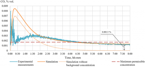
The results of the experimental study on the temporal variation of carbon monoxide concentration in the TVD cross section after chamber C15 are presented in Figure 4 (blue curve). The time sequence begins at the moment of blasting operations. The initial peak gas concentration reaches approximately 0.008%, followed by a decrease. The experimental curve in Figure 4 reveals a sharp drop in gas concentration during the first 15 minutes after ventilation begins, followed by a gradual rise in concentration between 15 minutes and 1 hour 30 minutes.
The rapid initial removal of gas after blasting and the commencement of ventilation is attributed to the explosive expansion of gases, which propels them away from the dead-end face over a certain distance (initial gas zone, as shown in Figure 2). This effect is further amplified by the collapse of broken ore immediately after the blast. During this brief initial phase, when the gas forms a concentrated cloud within the workings, mass transfer may also be enhanced by convection driven by minor differences in the densities of gas and air. Determining the extent of the initial gas zone is inherently challenging due to its dependence on numerous random factors.
In the numerical simulation results, represented by the orange curves in Figure 4, the length of the initial gas zone from the dead-end face was treated as an adjustable parameter to achieve optimal agreement with experimental data. Another critical adjustable parameter in the model is the effective gas yield, b, of the explosive (in terms of CO) [26]. Combined with the length of the initial gas zone, which represents the distance over which gas is ejected during detonation, these parameters enable the calculation of the initial gas concentration in the dead-end chamber. This value serves as an important input for numerical simulations.
The initial gas concentration is calculated using the following formula:
$C_0=\frac{A \cdot b}{1000 \cdot V}$ (5)
where, A is the mass of the explosive being detonated, kg; b is the gas yield of the explosive, l/kg; V is the volume of the chamber space filled with gas, m³.
Through model validation, b was determined to be 8.44 l/kg, and the initial gas dispersion zone length was set at 50 m. These values were used to achieve the best agreement between the numerical model and experimental results.
The model successfully replicated the peak gas concentration (calculated peak concentration: 0.0084%) and the exponential decay in gas concentration over the 2-8 hour period. Interestingly, the theoretical curve aligns well with the experimental data for times exceeding 2 hours only when a background gas concentration of 0.0013% by volume is incorporated into the model. Physically, this background concentration can be attributed to residual gases from combustion engine equipment in the mine, which results in air with a non-zero gas concentration—albeit below the maximum permissible level—entering the working area. For comparison, the results of the model without accounting for this background concentration are shown in Figure 4 as a dashed orange curve.
Figure 4. Comparative analysis of the time dependence of carbon monoxide concentration at the TVD
Additionally, the peak gas concentration in the model is reached with a slight delay. This delay arises from the omission of two key factors: the inertia of the gas as it is expelled from the dead-end face and the influence of buoyancy forces. In this study, when calculating the transport of the harmful impurity, we assumed that the density of the impurity is approximately equal to the density of air, thereby neglecting the effect of buoyancy forces.
Notably, the model fails to capture the sharp subsequent decrease in concentration observed in the experimental curve. This discrepancy is attributed to the influence of the mined-out space in the panel, which is not accounted for in the current model. According to our preliminary estimates, the exhausted space is capable of explaining the local minimum in gas concentration in the period 0:20-0:30, however, a detailed analysis of this effect on a large-scale model is beyond the scope of our study. The focus of this study is the ventilation dynamics of a single dead-end chamber following blasting operations. Of greatest interest to us are precisely the long periods of time (two hours or more), when gas concentrations decrease to values below the MPC. For these purposes, the simple model we use is acceptable.
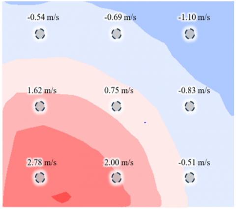
Figure 5 shows the distribution of air velocities in the TVD cross-section. In a portion of the section, elevated air velocities are observed, primarily due to the influence of the booster fan positioned upstream, just before the junction with the dead-end chamber. The air velocity at the fan outlet reaches approximately 25 m/s. However, when the air jet reached the cross-section under study, the peak velocity dropped significantly due to the jet opening and was about 2.7-3 m/s.
Figure 5. Comparative analysis of calculated and measured air velocities on the TVD at 4.5 meters after pairing with the camera
Simultaneously, a portion of the air in the studied section of the TVD recirculates back to the fan's suction area. This recirculation occurs due to a difference between the amount of air supplied to the mining section and the performance of the booster fan. These recirculation zones are highlighted in blue in the figure. The measured air velocities at specific points, previously identified during experimental measurements, are also shown. While the modeled airflow pattern closely aligns with the experimental observations in terms of direction and behavior, small discrepancies in absolute air velocity values are observed. These differences can be attributed to the movement of self-propelled equipment, technical nuances in the measurement procedures, and the limitations of the instruments used. Overall, the model was able to capture very well both the peak air velocity and the area where the return flows begin.
The concentration of carbon monoxide in the TVD drops below the MPC value after 4.5 hours of ventilation, consistent with the experimental results (see Figure 4). After 8 hours of ventilation, the CO concentration stabilizes at approximately 0.0013% by volume, which corresponds to the specified background concentration.
From this observation it follows that one of the promising measures to reduce the ventilation time of a dead-end chamber is to decrease the initial concentration of gas entering the mining section. Technically, this can be achieved by using electric transport or modern equipment equipped with Tier 4 internal combustion engines [27, 28]. The dotted orange curve in Figure 4 indicates that the time required for the concentration in the TVD to decrease to the MPC level is approximately 2 hours.
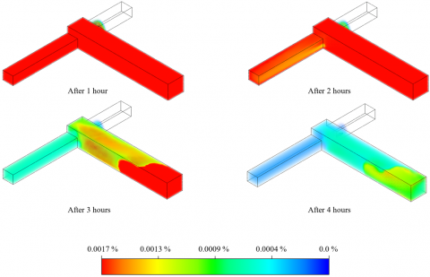
Figure 6 presents the calculated distributions of gas impurities at different time intervals (1, 2, 3, and 4 hours) for the scenario where the gas concentration at the entrance to the mine section is zero.
Figure 6. Distribution of volumetric gas concentration in a dead-end chamber at different moments after the start of ventilation
Based on Figure 6, after one hour of ventilation, the MPC is exceeded in all cross-sections of the chamber, corresponding to a carbon monoxide concentration exceeding 0.0017%. A similar situation is observed after 2 hours. However, after 2 hours of ventilation, the concentration of toxic gas in the TVD reaches safe levels, while the chamber area achieves an acceptable level of gas content only after 4 hours.
These findings highlight the challenges of ventilating large-section workings up to 70 meters in length following blasting operations under the specified conditions (cross-sectional area and air velocity in the TVD at its junction with the dead-end chamber). This raises an important question: how do the geometric parameters of the cross-sections of the mine workings affect ventilation efficiency?
To address this, a series of numerical calculations were conducted as part of this study, exploring various ventilation parameters for the workings. Table 2 presents the geometric parameters of the analyzed workings, as well as related quantities, including the air velocity at the entrance to the calculation area and the amount of explosive material detonated simultaneously.
To ensure consistent simulation conditions based on the initial parameters, the following adjustments were made:
•The amount of explosives was reduced proportionally to the decrease in the cross-sectional area of the dead-end chamber to achieve the same initial gas concentration in the chamber.
•The air velocity at the entrance to the calculation area was increased to maintain the same volume of air supplied to the system.
Table 2. Simulation parameters
|
No. |
Air Velocity at the Inlet Zone (m/s) |
Dead-End Chamber: - Width (m) - Height (m) - Area (m2) |
TVD: - Width (m) - Height (m) - Area (m2) |
Mass of Explosives (kg) |
|
1 |
0.300 |
- 12.0 - 11.0 - 132.0 |
- 8.0 - 6.5 - 52.0 |
591.2 |
|
2 |
0.432 |
- 10.0 - 9.2 - 91.7 |
- 6.7 - 5.4 - 36.1 |
410.7 |
|
3 |
0.507 |
- 9.2 - 8.5 - 78.1 |
- 6.2 - 5.0 - 30.8 |
349.8 |
|
4 |
0.768 |
- 7.5 - 6.9 - 51.6 |
- 5.0 - 4.1 - 20.3 |
231.1 |
|
5 |
1.200 |
- 6.0 - 5.5 - 33.0 |
- 4.0 - 3.3 - 13.0 |
147.8 |
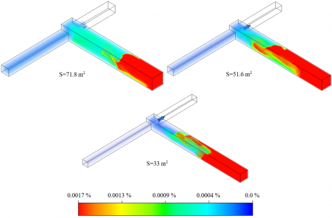
All other boundary conditions remained unchanged. Figure 7 presents the results of the simulated gas distribution following blasting operations, showing the conditions after 8 hours of ventilation.
Figure 7. Calculated gas distributions in dead-end chambers of different cross-sections after 8 hours of ventilation
Figure 7 shows that in dead-end chambers with cross-sectional areas of 91.7 m² and 132 m², no zones with gas concentrations exceeding the MPC remain after 8 hours of ventilation. In the chamber with the largest cross-section, there are virtually no traces of toxic gas. Conversely, in chambers with smaller cross-sectional areas (71.8 m² and below), a portion of the contaminated air volume near the dead-end face remains largely unaffected, even after 8 hours of ventilation. The red zone, indicating gas concentrations above the MPC, extends farther as the cross-section decreases.
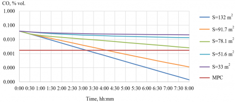
This trend is also evident in Figure 8, which illustrates the time-dependent changes in the average gas concentration within the chambers. The average gas concentration was calculated for the entire volume of each dead-end chamber.
Figure 8. Time dependences of the average gas concentration in chambers of different cross-sections
Analyzing the curves in Figure 8, it can be concluded that gas concentration decreases over time during ventilation for workings with different cross-sections. In all cases, the relationship follows an exponential trend, as evidenced by the linearity of the curves plotted on a logarithmic ordinate axis.
The minimum ventilation time for the dead-end chambers is 3 hours for a working with a cross-sectional area of 132.0 m² and 3 hours 53 minutes for a working with a cross-sectional area of 91.7 m². The slope angle of the curves, which characterizes the rate of decrease in gas concentrations, varies significantly (by an order of magnitude) among the curves. Additionally, the smaller the cross-section, the closer the slope angle approaches zero, indicating a slower rate of gas removal.
The presented curves were approximated using linear relationships between time t and the logarithm of concentrations log(C/C0). Based on these linear approximations, the dependence of carbon monoxide concentration C on ventilation time was determined as follows:
$C=C_0 \cdot e^{-\beta \cdot t}$ (6)
where, C0 is the initial gas concentration (m³/m³), β is a dimensionless coefficient that accounts for the cross-sectional area of the dead-end chamber and is numerically expressed as β= −0.00466+0.000169⋅S, S is the cross-sectional area of the dead-end chamber (m²), and t is the ventilation time from the moment when the ventilation of the chamber begins (minutes).
The identified exponential relationship (6) indicates that the ventilation of dead-end chambers can be effectively described by the ideal mixing model [29, 30]. In this model, the airflow entering the chamber—caused by the partial opening of the jet traveling along the TVD at the junction with the chamber—mixes with the air already present in the chamber. Simultaneously, an equivalent volume of gas-contaminated air, characterized by an average concentration Ca, is displaced from the chamber. This process can be mathematically expressed using the gas mass balance equation:
$C_{i n} Q \Delta t+C_a V-C_a Q \Delta t=\left(C_a+\Delta C_a\right) V$ (7)
The first term on the left represents the inflow of fresh air with concentration Сin over the time interval Δt. The second term on the left accounts for the volume of gas present in the chamber at time t, while the third term represents the displacement of a portion of the contaminated gas from the chamber with concentration Ca. Here, Q denotes the airflow rate, and V is the volume of the chamber. The term on the right describes the reduction ΔCa in the average gas concentration in the chamber over the time interval Δt. The solution to Eq. (7) yields the exponential relationship described in Eq. (6).
The expression for β can be reformulated in a more universal form using the so-called form factor, which is numerically equal to the ratio of the working length to the square root of the working cross-sectional area, as introduced in reference [25]. This parameter is more convenient as it comprehensively accounts for the influence of the two primary geometric dimensions of the chamber on its ventilation characteristics, where L represents the length of the chamber.
$\beta=-0.00466+\frac{0.8291}{f^2}$ (8)
This formula is valid for the ventilation of dead-end chambers with a cross-sectional area greater than 28 m² (or f < 13.2). For chambers with a smaller cross-section, the removal of harmful impurities will occur over an extended period, and therefore, the concentration will not decrease within a single mining shift.
According to the obtained dependence, the time required for carbon monoxide concentration to reach the MPC level in headings with cross-sectional areas of 40.7 m² and 33 m², and a length of up to 70 meters, should be at least one day. This is because a portion of the polluted air in the dead-end chambers remains largely unaffected for a long time due to the slow diffusion processes.
At the same time, Figure 8 shows that the polluted air volume in the dead-end chambers, within 20-30 meters from the junction with the TVD, actively participates in the air exchange with fresh air from the TVD and decreases to permissible gas concentration levels. In this area, there is a large-scale vortex that ventilates the dead-end chamber and intensifying turbulent diffusion mass transfer in it. However, its influence does not extend beyond 20-30 meters, and the zone near the dead-end face remains essentially stagnant.
In this study, a three-dimensional numerical model was developed to simulate air and gas distribution in a dead-end chamber and its adjacent transport-ventilation drift. The model was parameterized and validated using results from experimental tests that included both stationary and dynamic measurements of air flow parameters.
During the model's validation, acceptable agreement was achieved with experimental data on carbon monoxide concentration changes over time, specifically within the interval corresponding to the monotonic decrease in gas concentration during the ventilation of a dead-end chamber after blasting operations.
The study experimentally demonstrated and theoretically confirmed that, under specific conditions, dead-end chambers with a cross-sectional area of 132 m² and a length of up to 70 meters can be ventilated via diffusion processes, provided there is a source of airflow turbulence in an adjacent working with through ventilation.
Simulations were conducted to analyze diffusion-based ventilation of dead-end chambers with varying geometric parameters after blasting operations. The analyzed range of mine working form factors $(f=L / \sqrt{S})$ was between 6.1 and 12.2. For the first time, it was determined that the time-dependent decrease in ventilation gas concentration follows an exponential pattern within a specific parameter range. The rate of gas concentration reduction in a dead-end chamber, characterized by the coefficient in the exponential decay equation, was found to depend strongly on the geometric parameters of the chamber (form factor). An increase in the cross-sectional area of the chamber, while maintaining its length, significantly enhances the removal rate of toxic impurities.
Based on the approximation of the time dependencies, an analytical expression was derived to calculate the gas concentration at any given point during ventilation. However, it should be emphasized that in chambers with a cross-sectional area of 28 m² or less (corresponding to form factors of 13.2 or higher), ventilation becomes indefinitely prolonged due to limitations imposed by diffusion processes. Therefore, it is recommended that such dead-end chambers be ventilated using a fan with a duct or by reducing the length of the dead-end chambers. These conclusions are valid for chambers with minimal influence from surrounding mined-out spaces, under conditions where the spread of a passive admixture is considered. This study may also be applicable to other types of mines with large cross-section workings ventilated by the turbulent effect of booster fans.
The work was carried out as part of a major scientific project funded by the Ministry of Science and Higher Education of the Russian Federation (Grant No.: 075-15-2024-535).
[1] Acuña, E.I., Lowndes, I.S. (2014). A review of primary mine ventilation system optimization. Interfaces, 44(2): 163-175. https://doi.org/10.1287/inte.2014.0736
[2] Semin, M.A., Levin, L.Y. (2019). Stability of air flows in mine ventilation networks. Process Safety and Environmental Protection, 124: 167-171. https://doi.org/10.1016/j.psep.2019.02.006
[3] Kanam, O.H., Ahmed, M.O. (2021). A review on underground mine ventilation system. Journal of Mines, Metals and Fuels, 69(2): 62-70. https://doi.org/10.18311/jmmf/2021/27334
[4] Xue, Y., Wang, J., Xiao, J. (2024). Bibliometric analysis and review of mine ventilation literature published between 2010 and 2023. Heliyon, 10(4): e26133. https://doi.org/10.1016/j.heliyon.2024.e26133
[5] García-Díaz, M., Sierra, C., Miguel-González, C., Pereiras, B. (2019). A discussion on the effective ventilation distance in dead-end tunnels. Energies, 12(17): 3352. https://doi.org/10.3390/en12173352
[6] Kamenskikh, A.A., Faynburg, G.Z., Semin, M.A., Tatsiy, A.V. (2024). Experimental study on forced ventilation in dead-end mine working with various setbacks of the ventilation pipeline from the working face. Mining Science and Technology, 9(1): 41-52. https://doi.org/10.17073/2500-0632-2023-08-147
[7] McPherson, M.J. (2012). Subsurface Ventilation and Environmental Engineering. Springer Science & Business Media, United States.
[8] Roach, S.A. (1981). On the role of turbulent diffusion in ventilation. The Annals of Occupational Hygiene, 24(1): 105-132. https://doi.org/10.1093/annhyg/24.1.105
[9] Nakariakov E.V., Grishin E.L., Levin, L.Y. (2024). Ventilation of large-section dead-end cleaning chambers under conditions of changing ore heap volume. Bulletin of the Tomsk Polytechnic University. Geo Assets Engineering, 335(9): 51-60. https://doi.org/10.18799/24131830/2024/9/4453
[10] Govorukhin, Y.M., Krivolapov, V.G., Paleev, D.Y. (2020). Study of aerodynamic features of dead-end workings ventilated due to turbulent diffusion. Bulletin of Tula State University. Earth Sciences, 1: 392-400. https://doi.org/10.46689/2218-5194-2020-1-1-392-400
[11] Kozyrev, S.A., Amosov, P.V. (2017). Estimation of aeration time in blind excavations: Methodological approach based on 3D numerical modeling. Vestnik of MSTU, 20(1): 5-12. https://doi.org/10.21443/1560-9278-2017-20-1/1-5-12
[12] Maltsev, S.V., Kazakov, B.P., Isaevich, A.G., Semin, M.A. (2020). Air exchange dynamics in the system of large cross-section blind roadways. Mining Information and Analytical Bulletin, 2020(2): 46-57. https://doi.org/10.25018/0236-1493-2020-2-0-46-57
[13] Gendrue, N., Liu, S., Bhattacharyya, S., Clister, R. (2023). An investigation of airflow distributions with booster fan for a large opening mine through field study and CFD modeling. Tunnelling and Underground Space Technology, 132: 104856. https://doi.org/10.1016/j.tust.2022.104856
[14] De Souza, E., Penner, K. (2020). Underground booster fan placement strategies. CIM Journal, 11(4): 266-273. https://doi.org/10.1080/19236026.2020.1828730
[15] Xu, J., Zhang, Q. (2022). CFD analysis of jet fan layout optimization at intersection of branch tunnel and main tunnel. In 2022 3rd International Conference on Geology, Mapping and Remote Sensing (ICGMRS), Zhoushan, China, pp. 20-23. https://doi.org/10.1109/ICGMRS55602.2022.9849394
[16] Zheng, X., Fu, S., Li, X., Li, L., Lu, Y. (2020). Spatial layout optimization of jet ventilation fan for the rectangular large section underwater tunnel. In CICTP 2020, pp. 1435-1447. https://doi.org/10.1061/9780784482933.123
[17] Menéndez, J., Merlé, N., Fernández-Oro, J.M., Galdo, M., de Prado, L.Á., Loredo, J., Bernardo-Sánchez, A. (2022). Concentration, propagation and dilution of toxic gases in underground excavations under different ventilation modes. International Journal of Environmental Research and Public Health, 19(12): 7092. https://doi.org/10.3390/ijerph19127092
[18] Kozyrev, S.A., Vlasova, E.A. (2021). Gas hazard of explosives used in the mining industry. Mining Industry Journal, 5: 106-111. https://doi.org/10.30686/1609-9192-2021-5-106-111
[19] Feng, X., Jiang, Z., Zhang, G., Luo, X., Zeng, F. (2022). Study on CO diffusion law and concentration distribution function under ventilation after blasting in high-altitude tunnel. Journal of Wind Engineering and Industrial Aerodynamics, 220: 104871. https://doi.org/10.1016/j.jweia.2021.104871
[20] Olkhovskiy, D.V., Parshakov, O.S., Bublik, S.A. (2023). Study of gas hazard pattern in underground workings after blasting. Mining Science and Technology (Russia), 8(1): 47-58. https://doi.org/10.17073/2500-0632-2022-08-86
[21] Wala, A.M., Vytla, S., Taylor, C.D., Huang, G. (2007). Mine face ventilation: A comparison of CFD results against benchmark experiments for the CFD code validation.
[22] Yi, H., Kim, M., Lee, D., Park, J. (2022). Applications of computational fluid dynamics for mine ventilation in mineral development. Energies, 15(22): 8405. https://doi.org/10.3390/en15228405
[23] Shih, T.H., Liou, W.W., Shabbir, A., Yang, Z., Zhu, J. (1995). A new k-ϵ eddy viscosity model for high Reynolds number turbulent flows. Computers & Fluids, 24(3): 227-238. https://doi.org/10.1016/0045-7930(94)00032-T
[24] Ilina Ekaterina, E., Il'ina Tamara, E., Denissenko, P.V. (2015). Applicability of various differential turbulence models in the calculation of supersonic gas jets. Journal Scientific and Technical of Information Technologies, Mechanics and Optics, 15(3): 11-19. https://doi.org/10.17586/2226-1494-2015-15-3-509-516
[25] Semin, M., Faynburg, G., Tatsiy, A., Levin, L., Nakariakov, E. (2024). Insights into turbulent airflow structures in blind headings under different ventilation duct distances. Scientific Reports, 14(1): 23768. https://doi.org/10.1038/s41598-024-74671-3
[26] Kolesov, E.V., Kazakov, B.P. (2020). Efficiency of ventilation of dead-end development headings after blasting operations. Bulletin of Tomsk Polytechnic University, Georesources Engineering, 331(7): 15-23. https://doi.org/10.18799/24131830/2020/7/2715
[27] Kobylkin, S.S., Kharisov, A.R. (2020). Design features of coal mines ventilation using a room-and-pillar development system. Journal of Mining Institute, 245: 531-538. https://doi.org/10.31897/PMI.2020.5.4
[28] Wallace, K., Prosser, B., Stinnette, J.D. (2015). The practice of mine ventilation engineering. International Journal of Mining Science and Technology, 25(2): 165-169. https://doi.org/10.1016/j.ijmst.2015.02.001
[29] Chung, I.P., Dunn-Rankin, D. (1998). Using numerical simulation to predict ventilation efficiency in a model room. Energy and Buildings, 28(1): 43-50. https://doi.org/10.1016/S0378-7788(97)00061-3
[30] Zhang, W., Zhang, W., Mizutani, K., Zhang, H. (2021). Decision-making analysis of ventilation strategies under complex situations: A numerical study. Building and Environment, 206: 108217. https://doi.org/10.1016/j.buildenv.2021.108217