Akram K. Mohammed*![]() | Raad H. Irzooki
| Raad H. Irzooki![]() | Hasan J. Mohammed
| Hasan J. Mohammed![]()
© 2025 The authors. This article is published by IIETA and is licensed under the CC BY 4.0 license (http://creativecommons.org/licenses/by/4.0/).
OPEN ACCESS
High flow energy is one of the most important things that must be studied and dissipated due to its negative effects on the safety of hydraulic structures, especially spillways. Numerous investigations have been carried out in which various techniques were employed to dissipate the flow energy produced by the water flow over the spillway. These techniques have shown promising results in terms of energy dissipation, and these techniques include the use of a stepped spillway, stilling basins, and hydraulic jumps. The current study aims to use a novel technology, which is covering the spillway with different lengths of porous concrete, whether for the traditional or stepped spillway, to show its effect on dissipating the flow energy generated over these structures. Forty-eight experiments were conducted in a laboratory open channel that included six flowrates and three ratios of porous concrete in addition to normal concrete for the conventional and stepped spillway models. The results showed that there is an increasing relationship between the porous concrete length and the energy dissipation for relatively high discharges and is constant for low discharges and the best ratio was 67%. The results also showed that there is a decreasing relationship with the Froude number at U/S, D/S and hydraulic jump location. The results of the stepped model were compared with conventional model and it was found that the stepped model performed better than the other, as the highest increase in the energy dissipation rate reached 29% at the discharge 36.12 L/sec when using 67% of porous concrete. It was also found that using the stepped model with porous concrete reduces the length of the stilling basin by a percentage fall between 32.8% to 100% of the total basin length, thus reducing the construction cost. An experimental equation was deduced to calculate the energy dissipation by conducting a statistical analysis of the laboratory data and it was found that this equation has good accuracy through the following statistical indicators Nash-Sutcliffe efficiency (NSE)=0.89, determination coefficient (R2)=0.83 and mean square error (MSE)=0.0027. The above results indicated that the use of porous concrete is a good and suitable alternative to normal concrete, which reduces the cost of constructing energy dissipators.
flow energy dissipation, stepped spillway, porous concrete, novel approach, open channels, stilling basins, hydraulic
A spillway is a hydraulic structure utilized to release surplus water from the reservoir to the downstream of dams [1]. There are two common types of spillways, one, called conventional or smooth Ogee spillway, and the second called stepped spillway. One of the oldest spillways with steps was built in Iraq around 694 B.C. to provide the water to Ninevah, the Assyrian capital city, from Khosr River dam [2]. The released water from dams would have a huge amount of kinetic energy that it gains from the potential energy in reservoirs. This energy should be dissipated to prevent erosion and scouring at the downstream ends of the spillway. Several methods were employed for this goal, including lining the weirs with rubbles and riprap and constructing steps at the downstream ends of the weirs [3]. Stepped spillways, an energy dissipation structure widely used in hydraulic engineering, have better energy dissipation rates than smooth spillways [4]. Stepped spillways have become a common method for managing flood releases over the past few decades. The spillway design, which is comprised of a succession of steps near the crest to the toe, is its defining feature; which leads to reduce the dimension and cost of the stilling basin at downstream while considerably increasing the rate of energy dissipation occurring along the spillway face. Many researchers have investigated the hydraulic characteristics of stepped spillways [5]. The stepped geometry can be horizontal, inclined (a)-upward, (b)-downward, or (c)-pooled [6]. Also, the studies [7-10] concluded that more energy is dissipated by using additional structures (sudden contraction, sills, and blocks) of different sizes in different arrangements on the steps, the study [11] finding that the non-uniform stepped configurations might induce some flow instabilities for smaller flow rates. Altogether, the results provide some practical information for alternative designs of stepped spillways with nonuniform step heights also [12] found that higher amounts of flow may occur through curved steps and the dissipated energy would increase by 10.5%. However, from the cost side, the steps may require an extra size for the spillway, which would add more material to the building [13]. The effectiveness of utilizing direction diverting blocks, or DDBs, mounted to the surface of an Ogee spillway in lowering the acceleration and dissipating the energy of the entering supercritical flow was also assessed by Al Zubaidy et al. [14]. This study deals with reducing the energy of falling water by using porous concrete at different lengths of the downstream slope of the stepped spillway to reduce the cost of constructing the stilling basins that are used for this purpose. Porous concrete is a modern technique where the mixture is made from cement, coarse aggregate, and water without using fine aggregate and is strengthened with a type of additives to increase compressive strength [15]. Many researchers have utilized porous concrete to produce porous paving blocks that have high porosity and infiltration like [16] which are used to investigate the water absorption rate in porous concrete paving blocks as a permeable pavement structure, also Mahdi et al. [17] used the developing porous concrete interlocking pavement blocks from recycled concrete aggregate for rainfall harvesting use.
Despite the many studies that focused on the use of different means to dissipate the energy of flow over the spillway, it is necessary to work on finding novel technologies that can be used to increase the dissipation of flow energy, which will be reflected in reducing the lengths of the stilling basins or eliminating them. This will lead to reducing the cost of constructing these facilities, which are considered of great importance within the cost of dam projects. On this basis, the porous concrete technology will be used in this study to line the surface of the downstream slope of the spillway with different lengths to demonstrate its ability and possibility of using it in dissipating the energy of falling water. It is worth noting that there is no previous study in which porous concrete was used to dissipate flow energy in hydraulic structures.
Porous concrete is a modern technology where the mixture is manufactured from cement, coarse aggregate and water without using fine aggregate and is reinforced with a type of additives to increase the compressive strength [15]. Many researchers have used porous concrete to produce porous paving blocks with high porosity and infiltration, such as Matthew et al. [16] investigated the water absorption rate of porous concrete paving blocks as a permeable paving structure, and Mahdi et al. [17] developed interlocking paving blocks of porous concrete from recycled concrete aggregates for use in rainwater harvesting.
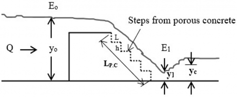
The dimensional analysis is a way to build the relation dimensionally between variables [18]. Dimensional analysis technique is used to find a relationship between variables that affect a specific problem by combining these variables that give dimensionless groups and knowing the relationship between them [19]. In this study, dimensional analysis will be used to know the dimensionless variables that affect the flow energy dissipation through the basic variables included in this study and depending on the basic equations of energy and flow over stepped spillway. As is known, Bernoulli's equation can be used to calculate the flow energy through any section in open channels, and thus the flow energy value can be found at any section, whether at the downstream or upstream of the spillway. Based on this principle, Bernoulli's equation was used to calculate the flow energy at the upstream (Eo) and downstream (E1), and then find the difference between them, which can be considered to represent the relative flow energy dissipation (ΔE/Eo), as shown in Figure 1.
Figure 1. Definition sketch of stepped spillway model
The parameters affecting on the flow passing over the stepped spillway will be conducted, as shown below [20, 21]:
$f_1\left(\frac{\Delta E}{E_o}, Q, F^*, N_s, y_{\circ}, y_c, g, \mu, \rho, y_1, L_{p . c}, \emptyset, L, h\right)=0$ (1)
$\frac{\Delta E}{E_o}=f_2\left(F^*, F_r, R_e, \emptyset, N_s, L_{p . c}, \frac{y_0}{y_c}, \frac{y_1}{y_c}, \frac{L}{y_c}, \frac{h}{y_c}\right)$ (2)
It is noted that in these kinds of problems, certain dimensionless parameters in Eq. (2), including the Reynolds number (Re), have a minor impact [22]. Furthermore, some parameters, such ($\emptyset, N_s, \frac{L}{y_c}, \frac{n}{y_c}, F^*$), are considered as constant because they are not changed in each test and can therefore be removed. Therefore, Eq. (2) becomes:
$\frac{\Delta E}{E_o}=f_3\left(F_r, L_{p . c}, \frac{y_{\circ}}{v_c}, \frac{y_1}{y_c}\right)$ (3)
Table 1 lists the dimensions for each parameter that affect the flow energy dissipation over stepped spillway.
Table 1. The parameters definition
|
Parameter |
Definition |
Dimensions |
|
Q |
Flowrate |
L3T-1 |
|
F⃰ |
Friction Froude number |
M0L0T0 |
|
Ns |
Number of steps |
M0L0T0 |
|
yo |
(U/S) Water depth |
L |
|
yc |
Critical flow depth |
L |
|
y1 |
(D/S) Water depth |
L |
|
g |
Gravity acceleration |
LT-2 |
|
$\mu$ |
Dynamic viscosity |
ML-1T-1 |
|
$\rho$ |
Mass density |
ML-3 |
|
LP.C |
Porous concrete ratio |
M0L0T0 |
|
$\emptyset$ |
Porous concrete porosity |
M0L0T0 |
|
L |
Step length |
L |
|
h |
Step height |
L |
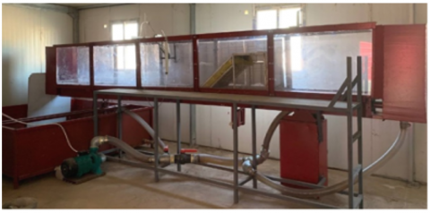
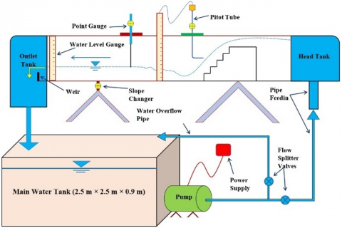
The laboratory experiments were conducted in a laboratory open channel with a steel structure and glass sides. The length of the channel is 7 m, its height is 0.8 m and its width is 0.5 m. This open channel contains a head tank at upstream to receive the water flowing from the pump, the purpose of this basin to dissipate the turbulence and eddies that occur as a result of the water exit from feeding pipe into this basin. At the downstream side, this open channel also contains an outlet tank to collect the water coming from upstream and falling to the main tank. where water is supplied to it by an electric pump as shown in Figure 2 and Figure 3. Two-point gauges were used in this open channel to measure the water depth and water surface profile along the reach.
The open channel contains a weir at its end to measure the discharge and a point gauge to measure the water level. The model of the stepped spillway was installed at a distance of 1.5 m from the upstream of the open channel. The model of the stepped spillway was made of a steel structure covered with plastic material, and the gaps were filled with silicone to prevent water leakage as shown in Figure 4 and Figure 5.
Figure 2. Laboratory open channel
Figure 3. Schematic of the open channel used in this study
Figure 4. Installed of the model
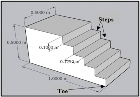
Figure 5. Dimensions of the stepped spillway model
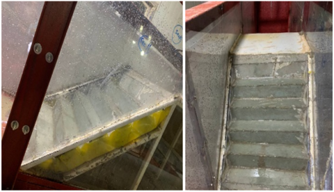
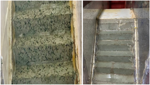
Figure 6. Normal and porous concrete steps of the stepped spillway model
The steps for the model of the stepped spillway were made of normal and porous concrete as shown in Figure 6. The necessary laboratory tests were also conducted for the specifications of normal and porous concrete listed in Table 2. In this study, a series of laboratory experiments were conducted where six discharges 10.67, 15.43, 20.23, 25.15, 30.36 and 36.12 L/sec and three length ratios for porous concrete 33%, 67% and 100% were used in addition to normal concrete to compare the results of normal concrete with porous concrete. The results obtained from this study were also compared with the results of another laboratory study using the conventional spillway model, which was conducted in the same way.
Table 2. Specification of the normal and porous concrete
|
Material |
Properties |
Test Results |
|
Normal concrete (N.C) |
Concrete Mix Ratio (Cement: Sand: Gravel: W/C) |
1: 1.5: 3: 0.4 |
|
Compressive Strength (MPa) |
41.87 |
|
|
Flexural Strength (MPa) |
4.24 |
|
|
Density (kg/m3) |
2381 |
|
|
Permeability Coefficient (cm/sec) |
- |
|
|
Total Porosity (%) |
- |
|
|
Effective Porosity (%) |
- |
|
|
Porous concrete (P.C) |
Concrete Mix Ratio (Cement: Sand: Gravel: W/C) |
1: 0: 3: 0.4 |
|
Compressive Strength (MPa) |
13.27 |
|
|
Compressive Strength with Add (Silica Fume) of (10%) from Cement Weight (MPa) |
24.14 |
|
|
Flexural Strength (MPa) |
1.87 |
|
|
Density (kg/m3) |
1804 |
|
|
Permeability Coefficient (cm/sec) |
0.976 |
|
|
Total Porosity (%) |
32.27 |
|
|
Effective Porosity (%) |
26.53 |
4.1 Effect of the porous concrete length $L_{P.C}$ on $\frac{\Delta E}{E_o}$
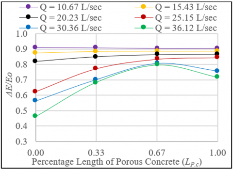
The data of the stepped spillway model were analyzed and the relationship between the relative flow energy dissipation and the length ratio of the porous concrete was plotted in Figure 7 for all the flowrates used in this study. This figure shows that the value of relative flow energy dissipation is almost constant when using normal and porous concrete at relatively low discharges such as 10.67 L/s, 15.43 L/s, and 20.23 L/s, noting that the energy dissipation ratio reached its peak of 90% at the lowest discharge 10.67 L/sec and then decreased to 86% and 82% at discharges 15.43 and 20.23 L/sec respectively. But, at the discharge 25.15 L/sec the value of the relative flow energy dissipation is 62% at using normal concrete and increases directly to 77%, 83% and 84% in the cases of using porous concrete 33%, 67%, and 100% respectively.
Figure 7. Relationship between LP.C and $\frac{\Delta E}{E_o}$ with used different flowrates
The results also show that using a percentage of 67% of porous concrete generally is considered one of the best percentages for the discharges 30.36 L/sec and 36.12 L/sec used. This is because at low discharges, a flow system called Nappe flow regime occurs. A partial or fully developed hydraulic jump may occur as a result of the nappe flow through the steps of the spillway which leads to the dissipation of energy [2]. These reasons, in general, reduce the friction of water with the steps surface, which eliminates the effect of porous concrete. In this case, the dissipation of flow energy is generally due to the obstruction resulting from the steps, not the porous concrete. High discharges cause the flow over the stepped spillway to become skimming, which limits the steps' impact. As a result, the impact of porous concrete on energy dissipation will be evident because some of the flow over the spillway will seep into it, increasing energy dissipation in comparison to normal concrete.
4.2 Effect of Froude number on the $\frac{\Delta E}{E_0}$
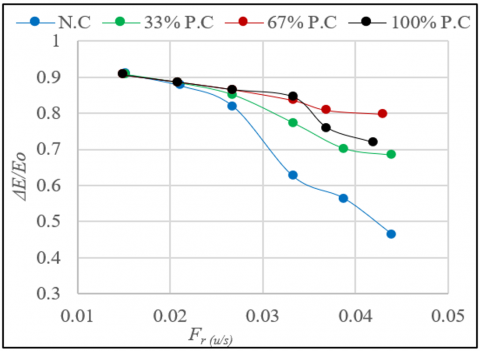
The data related to the Froude number at the upstream $\mathrm{U} / \mathrm{S}$, toe of the model $\mathrm{D} / \mathrm{S}$ and at the location where hydraulic jump occurs $F_{r(u / s)}, F_{r(t o e)}, F_{r(1)}$ were analyzed. Figure 8 represents the relationship between $F_{r(u / s)}$ and $\frac{\Delta E}{E_o}$. This figure shows that there is an inverse relationship between $F_{r(u / s)}$ and $\frac{\Delta E}{E_0}$. It appears from this relationship that the best values of the relative flow energy dissipation were at the discharge 10.67 $\mathrm{L} / \mathrm{sec}$ and $15.43 \mathrm{~L} / \mathrm{sec}$ whether using normal or porous concrete. The results also show that the effect of using porous concrete will be significant at high discharges such as 25.15 $\mathrm{L} / \mathrm{sec}$, $30.36 \mathrm{~L} / \mathrm{sec}$ and $36.12 \mathrm{~L} / \mathrm{sec}$, where a significant difference appears in the value of the relative flow energy dissipation.
Figure 8. Relationship between $F_{r(u / s)}$ and $\frac{\Delta E}{E_o}$ with normal and porous concrete
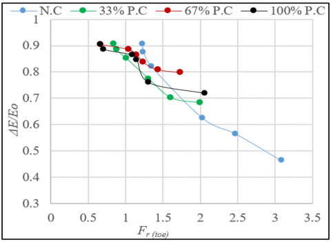
As for the Froude number at the toe $F_{r(t o e)}$ and its effect on the relative flow energy dissipation $\frac{\Delta E}{E_o}$, it is shown in Figure 9. This figure shows that there is an inverse relationship and that the best values for the dissipation of flow energy were obtained while employing 67% porous concrete as an alternative to normal concrete. Additionally, it is seen that $F_{r(t o e)}$ drops at all discharges when porous concrete is used instead of normal concrete, and the drop is particularly noticeable from 3.09 to 1.73 when the greatest discharge, $36.12 \mathrm{~L} / \mathrm{sec}$, is passed. It is important to note that the relationship between $F_{r(t o e)}$ and $\frac{\Delta E}{E_o}$ is unclear in relatively small flowrates, whether using normal or porous concrete, due to the flow conditions over the stepped spillway model and the effects of the steps, which cause the flow to behave as the nappe flow regime, partial nappe flow regime, or transitional flow regime.
Figure 9. Relationship between $F_{r(t o e)}$ and $\frac{\Delta E}{E_O}$ with normal and porous concrete
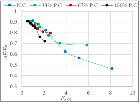
Figure 10 shows the relationship between the Froude number at the location of the hydraulic jump $F_{r(1)}$ and the relative flow energy dissipation $\frac{\Delta E}{E_o}$. This relationship demonstrates that there is an inverse relationship between them. It also notes that the relatively low discharges give similar values for flow energy dissipation and that the best porous concrete ratio is $67 \%$, which gives high values of $\frac{\Delta E}{E_o}$ and low values of $F_{r(1)}$. Also, it can be seen that when using $100 \%$ of porous concrete instead normal concrete and passing maximum discharge $36.12 \mathrm{~L} / \mathrm{sec}$, the hydraulic jump was transferred from Steady Jump $F_{r(1)}=8.2$ to Weak Jump $F_{r(1)}=2.13$. This large change in Froude number has a powerful effect on energy dissipation and thus greatly reduces the length of the stilling basins.
Figure 10. Relationship between $F_{r(1)}$ and $\frac{\Delta E}{E_o}$ with normal and porous concrete
4.3 Effect of U/S water depth on the $\frac{\Delta E}{E_o}$
It was noted from Figure 11 that there is a direct relationship between the ratio of the upstream water depth to the critical water depth $\frac{y_o}{y_c}$ and the relative flow energy dissipation $\frac{\Delta E}{E_0}$, where the value of the flow energy dissipation increases as the depth at the front of the spillway model increases. This is attributed to the fact that the depth of the water increases when the velocity decreases with constant discharge, and thus the flow is closer to the laminar flow and the effect of viscosity and friction appears more, which increases the dissipation of flow energy.
It was also noted that the value of the flow energy dissipation is same at low flowrates such as 10.67 L/sec and 15.43 L/sec when using both normal and porous concrete. For high flowrates 20.23 L/sec, 25.15 L/sec, 30.36 L/sec and 36.12 L/sec, it can be seen that a significant differences in the values of the relative flow energy dissipation $\frac{\Delta E}{E_o}$ when using porous concrete instead of normal concrete. Additionally, it seems that when utilizing porous concrete at a ratio of 67%, the flow energy dissipation value at discharges 30.36 L/sec and 36.12 L/sec is about 81% and 80%, respectively, whereas when using normal concrete, the energy dissipation is 56% and 46%.
Figure 11. Relationship between U/S water depth and $\frac{\Delta E}{E_o}$ with normal and porous concrete
4.4 Effect of D/S water depth on the $\frac{\Delta E}{E_o}$
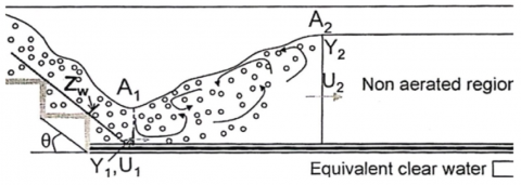
One of the most important parts in inspecting the remaining potential energy at the base of any hydraulic structures is the validity of estimating the energy amount. Therefore, there are several methods for calculating the amount of energy dissipation of the flow at the downstream of the stepped spillway model, in which the D/S water depth y1 is aerated and therefore the depth of the solid water must be calculated to give reasonable results. Some researchers have focused on using the indirect method for calculating the sequent depths of a hydraulic jump [8, 23], which assumes that the depth of flow downstream of the jump is equal to the upstream sequent depth. The finding showed an acceptable result for the stepped chutes spillway [20] and could be implemented with minimal difficulty for the aerated wavy flow [8]. The principle consists of measuring the downstream sequent depth, y2 in the non-aerated tail water of the hydraulic jump to estimate the upstream sequent depth y1 as shown in Figure 12 from the mass and momentum conservation equations.
Figure 12. The hydraulic jump profile in stepped chute [8]
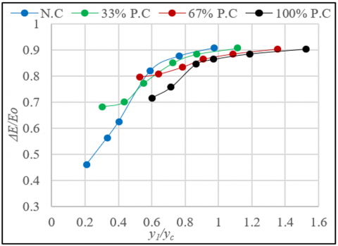
By using the method mentioned later, the value of flow energy dissipation and the value of flow depth y1 at the downstream of the stepped spillway model were calculated, and thus the value of $\frac{y_1}{y_c}$ was calculated. It is clear from Figure 13 that there is a direct relationship between $\frac{y_1}{y_c}$ and $\frac{\Delta E}{E_o}$ where it appears that the values of flow energy dissipation are close to each other at low flowrates 10.67 L/sec, 15.43 L/sec and 20.23 L/sec when using normal or porous concrete.
The figure also shows that the difference in relative flow energy dissipation appears at high flowrates 25.15 L/sec, 30.36 L/sec, and 36.12 L/sec. It was also noted that the values of $\frac{y_1}{y_c}$ increase when using porous concrete at higher ratios of porous concrete, and this is attributed to the fact that reducing the value of flow energy leads to the flow being tardy and with low velocity, which increases the depth of flow y1.
Figure 13. Relationship between D/S water depth and $\frac{\Delta E}{E_o}$ with normal and porous concrete
4.5 Comparison between conventional and stepped spillway model
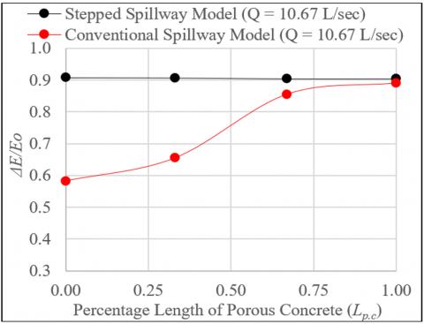
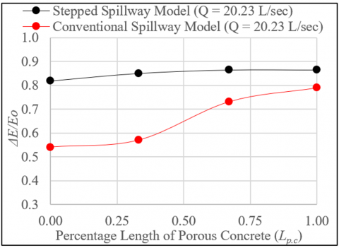
After studying all the factors affecting on the dissipation of flow energy in the stepped spillway model, it is necessary to make a comparison between another conventional spillway model which investigated by same researchers in terms of the performance and efficiency of each model based on the laboratory data that were obtained. The relationship between the relative flow energy dissipation $\frac{\Delta E}{E_o}$ and the percentage length of porous concrete $L_{P.C}$ was plotted for each flowrate separately for both conventional and stepped spillway models as shown in Figures 14-16.
Figure 14. Relationship between $\frac{\Delta E}{E_o}$ and LP.C for Q = 10.67 L/sec
Figure 15. Relationship between $\frac{\Delta E}{E_o}$ and LP.Cfor Q = 20.23 L/sec
Figure 16. Relationship between $\frac{\Delta E}{E_o}$ and LP.C for Q = 30.36 L/sec
In general, when comparing the conventional spillway model with the stepped spillway model, it appears that the stepped spillway model is better than the conventional spillway model in terms of dissipating flow energy, due to the advantage of the steps, the presence of which leads to more obstruction of flow than the conventional spillway model.
However, when comparing them with use of porous concrete, we find that the stepped spillway model is also better than the conventional spillway model as shown in Table 3.
It is noted from the table above that the stepped spillway in the case of using normal concrete has an effect on energy dissipation when passing low discharges. For example, when the passing discharge equal to 10.67 L/sec, it is noted that the energy dissipation ratio increased from 58% to 91% when using the stepped spillway instead of the normal one, while when using porous concrete, the dissipation ratio changed from 89% to 90% when using the conventional and stepped spillway, respectively. According to these findings, the conventional spillway is preferable to the stepped one when employing porous concrete in low discharges because the stepping process will not improve energy dissipation. In the case of passing high flow rates, it is preferable to use a stepped spillway with porous concrete because it has a great effect in dissipating energy instead of using a spillway with normal concrete. For example, at a flow rate of 36.12 L/sec, it is noted that the energy dissipation ratio increased from 37% to 46% when using a stepped waterway with normal concrete instead of a conventional spillway, while the ratio increased to 72% when using porous concrete.
Table 3. Differences between relative flow energy dissipation for conventional and stepped spillway model
|
Condition |
Model Type |
Flowrates (L/sec) |
|||||
|
10.67 |
15.43 |
20.23 |
25.15 |
30.36 |
36.12 |
||
|
Value of $\frac{\Delta E}{E_0}$ |
|||||||
|
N.C |
Conventional |
58% |
54% |
54% |
50% |
42% |
37% |
|
Stepped |
91% |
88% |
82% |
62% |
56% |
46% |
|
|
33% P.C |
Conventional |
66% |
63% |
57% |
52% |
45% |
40% |
|
Stepped |
91% |
88% |
85% |
77% |
70% |
68% |
|
|
67% P.C |
Conventional |
86% |
81% |
73% |
66% |
55% |
51% |
|
Stepped |
90% |
89% |
86% |
83% |
81% |
80% |
|
|
100% P.C |
Conventional |
89% |
84% |
79% |
76% |
66% |
60% |
|
Stepped |
90% |
89% |
86% |
84% |
76% |
72% |
|
4.6 Effect of using porous concrete on the stilling basin length
Stilling basins are important hydraulic structures designed at the downstream of the spillway. Their main function is to reduce the flow velocity and dissipate energy through the large basin area and presence of the baffles, sills and chute blocks at different locations in the basin. On this basis, in this study, a comparison was done between the length of the required stilling basin in case of using normal concrete and porous concrete by performing the required calculations and according to the data obtained and listed in Table 4.
Table 4. Hydraulic jump characteristics and length decreases in stilling basin due to use the porous concrete at the stepped spillway model
|
Condition |
Flowrates (L/sec) |
|||||
|
|
10.67 |
15.43 |
20.23 |
25.15 |
30.36 |
36.12 |
|
|
Froude Number at Jump Location Fr(1) |
|||||
|
N.C |
1.04 |
1.5 |
2.21 |
3.94 |
5.2 |
8.2 |
|
100% P.C |
0.6 |
0.8 |
1.05 |
1.3 |
1.65 |
2.2 |
|
|
Initial Depth, y1 (cm) |
|||||
|
N.C |
2.5 |
2.6 |
3 |
3.2 |
3.8 |
4.5 |
|
100% P.C |
3.6 |
4 |
5 |
5.2 |
5.5 |
6.3 |
|
|
Sequent Depth, y2 (cm) |
|||||
|
N.C |
10.5 |
12.5 |
13 |
13.5 |
14.5 |
17 |
|
100% P.C |
11 |
15 |
15 |
17 |
18 |
20 |
|
|
Required Length of Stilling Basin (cm) |
|||||
|
N.C |
40 |
49.5 |
50 |
51.5 |
87 |
102 |
|
100% P.C |
No need |
No need |
No need |
No need |
No need |
68.5 |
|
|
Ratio of Stilling Basin Length Reduction Due to Use the (P.C) Instead the (N.C) |
|||||
|
|
100% |
100% |
100% |
100% |
100% |
32.8% |
The information in Table 4 makes it evident that there is a significant difference in the length of the stilling basin that is needed. The results indicate that at flowrates of 10.67 L/sec to 30.36 L/sec there is no need for a stilling basin because the Froude number values are less than 2 [24], but at discharge 36.12 L/sec, the percentage of reduction in the length of the required stilling basin is 32.8% in case of using porous concrete as an alternative to normal concrete.
These findings demonstrate how well porous concrete works to shorten the stilling basins, which will result in a significant reduction in the building cost of this structure.
Based on the statistical program (IBM SPSS Statistics Version 25), the observed data in the laboratory were used and analyzed statistically using the non-linear regression analysis method. The experimental data was divided into two groups randomly. The first group about 65% of the experimental data which was used to obtain an equation to calculate the relative flow energy dissipation over stepped spillway by Non-Linear regression analysis as in Eq. (4).
$\frac{\Delta E}{E_o}=\frac{\left(\frac{y_o}{y_c}\right)^{-0.039} \times\left(\frac{y_1}{y_c}\right)^{0.267} \times\left(F_{r(\text { toe })}\right)^{-0.07}}{1.062^{\left(L_{p . c}\right)}}$ (4)
The performance of the regression model presented in Eq. (4) was evaluated by using quantitative statistical metrics, such as the MSE, R2 and the NSE [10, 25].
$N S E=1-\frac{\sum\left(\Delta E-\Delta E_P\right)}{\sum(\Delta E-\overline{\Delta E})}$ (5)
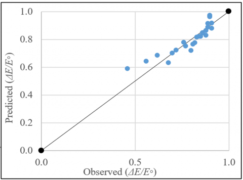
where, $\Delta E$ is the measured dissipated energy of flow, $\Delta E_P$ is the predicted dissipated energy of flow by the regression model, $\overline{\Delta E}$ is the average measured dissipated energy of flow. The second group about 35% of the experimental data which was used accuracy validation of the Eq. (4). Table 5 shows the quantitative statistical metrices, Finally, Figure 17 shows the fitting relationship between observed and predicted $\frac{\Delta E}{E_o}$.
Table 5. The quantitative statistical metrices result
|
NSE |
R2 |
MSE |
|
0.89 |
0.83 |
0.0027 |
Figure 17. Fitting relationship between observed and predicted $\frac{\Delta E}{E_0}$
The main conclusions of this study can be summarized as follows:
[1] Garg, S.K. (2005). Irrigation Engineering and Hydraulic Structures. Delhi: Khanna.
[2] Chanson, H. (1994). Aeration and deaeration at bottom aeration devices on spillways. Canadian Journal of Civil Engineering, 21(3): 404-409. https://doi.org/10.1139/l94-044
[3] Chanson, H., Paintal, A. (2003). Hydraulics of stepped chutes and spillways. Applied Mechanics Reviews, 56(1): B10–B11. https://doi.org/10.1115/1.1523365
[4] Anwar, N., Dermawan, V. (2011). An experimental study of flow depth and energy losses on stepped spillway of 45 degree of slope. In Proceedings of the 34th World Congress of the International Association for Hydro-Environment Research and Engineering: 33rd Hydrology and Water Resources Symposium and 10th Conference on Hydraulics in Water Engineering, Barton, ACT: Engineers Australia, pp. 2354-2363.
[5] Parsaie, A., Haghiabi, A.H. (2019). Evaluation of energy dissipation on stepped spillway using evolutionary computing. Applied Water Science, 9: 1-7. https://doi.org/10.1007/s13201-019-1019-4
[6] Murillo Munoz, R.E. (2006). Experimental study of the development flow region on stepped chutes. PhD thesis, University of Manitoba, Canada.
[7] Kauppi, F.J. (2002). Hydraulic energy dissipating offset stepped spillway. U.S. Patent No. 6,443,654. Washington, DC: U.S. Patent and Trademark Office.
[8] André, S., Schleiss, A. (2004). High velocity aerated flows on stepped chutes with macro-roughness elements. Ph.D. Thesis. https://doi.org/10.5075/epfl-thesis-2993
[9] Saleh, L.A., Khassaf, S.I. (2024). Evaluating the hydraulic performance of USBR II stilling basin with rough bed. Tikrit Journal of Engineering Sciences, 31(3): 93-104. https://doi.org/10.25130/tjes.31.3.9
[10] Abdulrasul, W.A., Mohammed-Ali, W.S. (2024). Experimental study of energy dissipation in sudden contraction of open channels. Instrumentation Mesure Métrologie, 23(1): 55-61. https://doi.org/10.18280/i2m.230105
[11] Felder, S., Chanson, H. (2011). Energy dissipation down a stepped spillway with nonuniform step heights. Journal of Hydraulic Engineering, 137(11): 1543-1548. https://doi.org/10.1061/(asce)hy.1943-7900.0000455
[12] Jahad, U.A., Chabuk, A., Al-Ameri, R., Majdi, H.S., Majdi, A., Al-Ansari, N., Abed, S.A. (2024). Flow characteristics and energy dissipation over stepped spillway with various step geometries: Case study (steps with curve end sill). Applied Water Science, 14(3): 60. https://doi.org/10.1007/s13201-024-02110-9
[13] Gonzalez, C.A., Chanson, H. (2004). Interactions between cavity flow and main stream skimming flows: An experimental study. Canadian Journal of Civil Engineering, 31(1): 33-44. https://doi.org/10.1139/L03-066
[14] Al Zubaidy, R.Z., Khedher, K.I., Darweesh, A.N. (2016). Energy dissipation on the ogee spillways by using direction diverting blocks. Journal of Engineering, 22(3): 77-88. https://doi.org/10.31026/j.eng.2016.03.06
[15] ACI Committee 522. (2010). 522R-10: Report on Pervious Concrete. American Concrete Institute, United States, pp. 1-38.
[16] Matthew, D., Hadiwardoyo, S.P., Iduwin, T., Lumingkewas, R.H. (2024). Water absorption rate in porous concrete paving block as a permeable pavement structure. E3S Web of Conferences, 517: 12003. https://doi.org/10.1051/e3sconf/202451712003
[17] Mahdi, M.M., Irzooki, R.H., Abdulrahman, M.B. (2021). Developing porous concrete interlocking pavement blocks utilizing recycled concrete aggregate for rainfall harvesting use. Tikrit Journal of Engineering Sciences, 28(3): 48-60. http://doi.org/10.25130/tjes.28.3.04
[18] Vennard, J.K., Street, R.L. (1976). Elementary Fluid Mechanics. John Wiley & Sons, Inc.
[19] Mohammed, A.K., Irzooki, R.H., Jamel, A.A., Mohammed-Ali, W.S., Abbas, S.S. (2021). Novel approach to computing critical and normal depth in circular channels. Mathematical Modelling of Engineering Problems, 8(6): 923-927. https://doi.org/10.18280/mmep.080611
[20] Al-Moula, S.J.S., Khalaf, R.M., Irzooki, R.H. (2014). Hydraulic characteristics of flow over stepped spillway with semicircular crest. Ph.D. Thesis, Al-Mustansiriyah University Library, Iraq.
[21] Jamel, A.A.J. (2018). Numerical simulation for estimating energy dissipation over different types of stepped spillways and evaluate the performance by Artificial Neural Network. Tikrit Journal of Engineering Sciences, 25(2): 18-26. https://doi.org/10.25130/tjes.25.2.03
[22] Hady, I.A., Mohammed, A.Y. (2024). Flow characteristics in vertical shaft spillway with varied inlet shapes and submergence states. Tikrit Journal of Engineering Sciences, 31(4): 34-45. https://doi.org/10.25130/tjes.31.4.4
[23] Díez-Cascón, J., Blanco, J.L., Revilla, J.A., García, R.F. (1991). Studies on the hydraulic behaviour of stepped spillways. International Water Power & Dam Construction, 43: 22-26.
[24] Peterka, A.J. (1964). Hydraulic design of stilling basins and energy dissipators (No. 25). United States Department of the Interior, Bureau of Reclamation.
[25] Nash, J.E., Sutcliffe, J.V. (1970). River flow forecasting through conceptual models part I—A discussion of principles. Journal of Hydrology, 10(3): 282-290. https://doi.org/10.1016/0022-1694(70)90255-6
[26] Irzooki, R.H., Mohammed, J.R., Ameen, A.S. (2016). Computational fluid dynamics modeling of flow over stepped spillway. Tikrit Journal of Engineering Sciences, 23(3): 1-11.
[27] Pegram, G.G., Officer, A.K., Mottram, S.R. (1999). Hydraulics of skimming flow on modeled stepped spillways. Journal of Hydraulic Engineering, 125(5): 500-510. https://doi.org/10.1061/(ASCE)0733-9429(1999)125:5(500)