Taha Abdulsalam Taha![]() | Saad Ahmed Ayoob*
| Saad Ahmed Ayoob*![]() | Mohammad Tariq Yaseen
| Mohammad Tariq Yaseen![]()
© 2025 The authors. This article is published by IIETA and is licensed under the CC BY 4.0 license (http://creativecommons.org/licenses/by/4.0/).
OPEN ACCESS
Optical fibers are exposed along their path in some areas to alignment or intersection with electric power transmission lines. A magnetic field is generated around electric waves in the form of rings. The magnetic field affects the optical signal transmitted through the optical fiber through the Kerr and Faraday phenomena. The main problem that the research addressed is the study of the effect of the magnetic field generated by the electric power transmission wires adjacent to parts of the optical network. The research methodology includes designing the basic network, identifying its parts, then simulating the effect of adding the magnetic field by using phase rotation and comparing the performance of the network with the presence and absence of the effect of the magnetic field. A proposed network was designed using OptiSystem7 for a fiber optic network. This research aims to propose and simulate a fiber-optic network by taking advantage of the aforementioned multiple properties to connect two sites of Mosul University. The magnetic field effect on the properties of the optical signal is studied in terms of maximum Q-factor (6.58649), bit error rate (1.626×10⁻¹¹), and other parameters. The results indicate, through the values of the signal quality factor, bit error rate, and other factors, that there is a slight effect of the magnetic field on the optical signal, which is almost negligible within the limits of current frequencies, but it may be a limiting factor for the optical network in light of future frequencies.
optical fibers, magnetic field, Kerr effect, faraday effect, Q-factor, bit error rate (BER), simulation, network design
Optical fibers are considered a fast data transmission method at the present time, while providing bandwidth, and with increasing bandwidth, wire prices rise and the cost is only in the process of building the network, as it is less susceptible to damage in the long run, and it is also a safe way to transmit data, as it is difficult to click on glass with a diameter of less than 1 mm without interrupting the communication channel, and it is also less vulnerable to theft because it is not of material value like copper wire, it is light in weight and does not carry current, which means that it does not pose a fire risk [1-3].
The two ends of the optical network are located across the two sides of the Tigris River in the city of Mosul. The network is extended in a joint bundle with various types of transmission lines across the third bridge in the city. Therefore, it was necessary to conduct a study to ensure that the optical signal was not affected by the magnetic field generated by the electrical power transmission lines adjacent to the optical network.
Researchers strive to meet the requirements of modern communications by enhancing data speed and increasing the distance between the sender and the recipient, Modern systems require faster data transmission and an increase in the distance between the sender and the receiver to save time and meet users’ needs for data as quickly as possible and at the lowest cost, as the optical signal via optical fiber reaches very long distances before the need to reshape the signal, thus saving the cost of using signal repeaters frequently at short distances [4]. Several approaches are used to comprise wireless, such as high frequency (millimeter-wave), and beamforming [5-7]. Or by using several communication technologies together to support the signal, especially at the edges of the cells. This is done by wireless connection to several adjacent towers, in addition to connecting the towers through optical fibers [8-10]. Optical fibers are a reliable and fast data transmission method at the present time, as the data transmission speed exceeds 10 Gb/s while providing bandwidth [11-13]. When the bandwidth is increased further, the cable prices rise, and the cost is only in the process of building the network, as it is less vulnerable to damage in the long run [14]. It is also a safe means of transmitting data, as it is difficult to tap on glass with a diameter of less than 1 mm without interrupting the communication channel, and it is less vulnerable to theft, as it has no material value like copper wire, and it is characterized by lightweight and does not carry current, which means that it does not pose a fire risk [1]. The effect of the magnetic field on the optical signal is the main problem under the subject of this research. At the end of the introduction, the research aims to answer a specific question, which is does the magnetic field significantly affect the optical signal?
The paper discussed previous works after the introduction and the importance of the topic. The third section included the effect of electromagnetic waves on the optical signal. The simulation results are in section 4, and the last section represents conclusions and future work.
In this study, the researchers dealt with the interference between electromagnetic waves and the optical signal transmitted by optical fibers. The nine-channel WDM wavelength division multiplexing technique was used. The calculation method was applied based on the nonlinear Schrödinger partial differential equation solution, and it is an approximation method of light wave propagation in optical fibers. Two different modulation methods were used with three different data transfer rates. It showed that the increase of the value of BER due to the influence of the magnetic field is little, but it can be observed [15].
The researchers developed a broadband analog optical fiber transmission system, studied the loss under the influence of electromagnetic fields, and converted the ultra-fast pulsed electric signal into an optical signal by means of photoelectric conversions [16].
In the study conducted by Liu et al. [17], two different types of gamma rays were used. The radiation-induced transient losses of pulsed gamma rays impinging on single-mode and multimode optical fibers were measured. Optical fiber transmission schemes with several wavelengths such as 1550nm were used in the experimental measurement. The results show that the radiation loss that the optical fiber is exposed to depends on the type of fiber. The results indicate that single-mode fibers may be affected to a lesser extent than multimode fibers [18].
Royer et al. [19] presented a computational model for the fiber-optical cable based on magnetic field sensors using the magneto-optical effect of Kerr and Faraday on the pole installation. IT suggested two sensors, one using a thin section of Fe and the other using a Ce-YIG layer. The analytical model based on the Fresnel equations was used to guide the construction of the numerical model on COMSOL Multiphysics. The results indicate the possibility of building high-accuracy sensors for a limited range of magnetic field strength levels.
This research aims to propose and simulate a fiber-optic network by taking advantage of the aforementioned multiple properties to connect the first and third campuses of the University of Mosul, with a study of the effect of the magnetic field on the optical signal transmitted through the optical fiber.
The proposed network extends across the third bridge of the city of Mosul, which is the area where the electric power transmission lines line up with the optical fibers linking the network. Therefore, the effect of the magnetic field may appear on the optical signal.
Electromagnetic wave fields surrounding fiber optic lines affect the optical signal through two phenomena [15]:
3.1 Electro-optic Kerr effect
It is a physical effect based on the change of the refractive index of materials depending on the strength of the electromagnetic field. This causes the refraction of light in the carrier medium, and the intensity of the light beam passing through the optical fiber itself plays a role in the strength of the influence of the electromagnetic field on it [20].
The Kerr effect is proportional to the square of the electric field output and depends on the medium's refractive index (n) with temperature (T). We find the value of the difference in the n of the optical medium due to the electro-optical Kerr effect by the equation [21]:
$\Delta n=\lambda K(\lambda) E^2$ (1)
∆n: the n difference inside the carrier environment.
λ: wave length.
λK: Kerr coefficient.
E: electric field intensity.
$K=\frac{1}{30} \frac{\left(n^2-1\right)\left(n^2+2\right)}{n} \frac{m \varepsilon_0}{\lambda k T}$ (2)
3.2 Faraday effect
The Faraday effect or Faraday rotation is a magneto-optical phenomenon that occurs as an interaction between light and the magnetic field in the medium. The Faraday effect causes the rotation of the polarization state of the level of light radiation. The chief condition for the Faraday effect occurrence is that the direction of the magnetic field is in the same direction as the path of the light waves. It is worth noting that the magnetic field is generated as rings surrounding the cable of the electric waves. Therefore, the direction of the magnetic field in the same direction as the light waves is not achieved except in the case of perpendicular to the electrical and optical waves, i.e., at the intersection of the optical cable with the cable carrying electrical energy. Therefore, if the intersection area is always small, then the Faraday effect is in a limited area. The angle β at which this rotation occurs is linearly proportional to the magnetic field directed in the direction of light propagation. The following equation shows the relationship between the angle of rotation of the polarization state and the magnetic field.
$B=d \vartheta \beta$ (3)
ϑ: Verdet constant.
B: magnetic field density.
d: the length of the path of interaction between the light and the magnetic field.
3.3 Verdet constant
The Verdet constant is a physical property used to describe the effect of a magnetic field on the polarization of light as it passes through a material. When light travels through a transparent material in the presence of a magnetic field, its plane of polarization may rotate by an angle proportional to the magnetic field strength and the length of the material. This phenomenon is known as the Faraday effect, and the Verdet constant quantifies the degree of rotation.
Mathematically, the relationship between the angle of rotation (θ) and the magnetic field strength (B) can be expressed as follows:
$\theta=V \times B \times L$ (4)
θ: angle of rotation in radians.
V: Verdet constant of the material (units: rad/(T*m)).
B: magnetic field strength in Tesla (T).
L: length of the material through which the light passes in meters (m).
The Verdet constant is unique to each material and is typically measured at specific wavelengths of light. It can vary significantly depending on the material's composition and the wavelength of light being used.
The Faraday effect and Verdet constant are essential in various scientific and engineering applications, including magneto-optical devices, fiber optic communications, and experimental physics research involving magnetic fields and light interactions.
The Verdet constant is one of the main factors associated with the Faraday effect, which describes the rotation of the polarization of light in certain media due to the magnetic field. The Verdet constant VB0 for a static magnetic field parallel to the path of light transmitted in refractive Faraday materials for a distance L with a constant wavelength λ and a polarization rotation angle θ0 is related by the following relationship [19]:
$\theta_0=V B 0(\lambda) B L=V H 0(\lambda) H L$ (5)
B: magnetic field density.
H: magnetic field intensity.
B=μ0H.
$V H 0=\mu 0 V B 0$ (6)
VH0: Verdet's H-field matter constant for rotation polarization.
μ0: vacuum permeability.
3.4 Simulation steps
This work proposes an ideal simulation of connecting two sites using fiber optic cable at a distance of 4683 meters with a bridge over the river, as shown in Figure 1. Studying the effect of electromagnetic waves of electric power lines adjacent to the optical fiber network on the optical signal through the Kerr and Faraday phenomena. The network was simulated using the OptiSystem7 program.
Figure 1. Optical cable path
An optical channel was made using different components to study the behavior of the optical link in terms of bit error rate and Q factor in addition to other factors. The technique used in the simulation was based on the non-return-to-zero (NRZ) modulation. Simulations are made for a continuous wave (CW) laser, and the optical network is designed as in Figure 2.
Figure 2. Components of the proposed network
A CW laser, or continuous wave laser, is a type of laser that emits a continuous, steady output of light over time, as opposed to pulsed lasers that emit light in short pulses. In a CW laser, the emission of light remains constant as long as the laser is powered on.
NRZ modulation which is a digital modulation technique used in data transmission. In NRZ modulation, a logical high (1) is represented by one level of the signal (e.g., a high voltage), and a logical low (0) is represented by another level (e.g., a low voltage). There is no return to a zero level during the duration of each bit.
The optical system in the Figure 2 includes a bit sequence generator through which we can change the data transfer rate. The (Mach-Zehnder) modulator is used to load the modulated electrical pulses onto the optical signal generated by the laser source. The optical signal generated from the MZ converter is transmitted via the optical cable (SMF) for a distance of 4683 meters. In this path, the exposed optical signal is affected by the magnetic field through the Kerr and Faraday phenomenon. The Faraday effect causes a rotation of the polarization state of the plane of light radiation. The rotation process was simulated using the (polarization phase shift) tool to represent the polarization change of the signal. A polarization controller is used on the receiver side to adjust the effect of the polarization rotation and optical signal recovery.
The simulation circuit was run using optisystem7 software. It included a simulation of the transmitting circuits, the receiving circuits, and the optical transmission line using the MZ modulation system with WDM wavelength division multiplexing technology and the values of the variables as in Table 1.
Table 1. The variables adopted in the design
|
Operation Parameters |
Values |
|
Random bit sequence |
2 |
|
Continues laser frequency |
2 |
|
Modulation type |
Mach Zehnder modulator |
|
Fiber optic length |
4683 m |
|
Fiber optic attenuation |
0.2 dB/Km |
The results are divided into two main parts: the results of the transmitted signal, which consists of two cases, and the other is the results of the received signal, which also consists of two cases.
4.1 Results of the transmitted signal
The signal polarity changes across the optical transmission line result of the Faraday effect or by changes in the refractive index of the medium according to the Kerr effect. A gradual decrease is observed in relation to the value of the Q coefficient when increasing the angle of rotation of the polarity, which is a negative indicator of the deterioration of the condition of the light signal. At the same time, there is an increased bit error rate which is also a negative factor. Here, the effect of the magnetic field on the optical signal appeared when the optical signal and the magnetic field were both in the same direction (x-direction) shown in Table 2.
Table 2. The magnetic field direction corresponds to the direction of the optical signal
|
Magnetic- Effect – ΔΦ – X Direction |
||||
|
Polarization Shifts by X |
Max Q Factor |
Min BER (10-11) |
Eye Height |
Threshold |
|
0 |
6.59352 |
1.55177 |
0.036230 |
0.1083010 |
|
5 |
6.59353 |
1.55185 |
0.362314 |
0.0108280 |
|
10 |
6.59349 |
1.55193 |
0.362318 |
0.0108260 |
|
15 |
6.59339 |
1.55289 |
0.036231 |
0.0108240 |
|
20 |
6.59323 |
1.55444 |
0.036231 |
0.010822 |
|
25 |
6.59302 |
1.55656 |
0.036231 |
0.0108206 |
|
30 |
6.59276 |
1.55924 |
0.036312 |
0.0108190 |
|
35 |
6.59244 |
1.56247 |
0.036230 |
0.0108177 |
|
40 |
6.59208 |
1.56624 |
0.036229 |
0.0108164 |
|
90 |
6.58649 |
1.626 |
0.036212 |
0.0108144 |
Table 3. The difference in the direction of the magnetic field and the optical signal
|
Magnetic- Effect – ΔΦ – X Direction |
||||
|
Polarization Shifts by Y |
Max Q Factor |
Min BER (10-11) |
Eye Height |
Threshold |
|
0 |
6.5935 |
1.55175 |
0.036230 |
0.1083010 |
|
5 |
6.5935 |
1.55175 |
0.036230 |
0.0108301 |
|
10 |
6.5935 |
1.55175 |
0.036230 |
0.0108301 |
|
15 |
6.5935 |
1.55175 |
0.036239 |
0.0108301 |
|
20 |
6.5935 |
1.55175 |
0.036230 |
0.0108301 |
|
25 |
6.5935 |
1.55175 |
0.036230 |
0.0108301 |
|
30 |
6.5935 |
1.55175 |
0.036230 |
0.0108301 |
|
35 |
6.5935 |
1.55175 |
0.036230 |
0.0108301 |
|
40 |
6.5935 |
1.55175 |
0.036230 |
0.0108301 |
|
|
No change |
No change |
|
|
In the second case, as a result of the fact that the direction of the magnetic field is not compatible with the direction of the optical signal, no change occurred in the factors. In other words, the magnetic field did not affect the optical signal, as shown in Table 3.
4.2 Results of the received signal
A phase corrector is used on the receiving side to reduce the effect of the magnetic field on the optical signal. In addition, it tries to compensate for the phase difference and helps restore the original signal. It is noted that the value of the coefficient (Q) improves while the bit error rate decreases with the increase in the modulation angle change value. Thus, the value of the received optical signal improves, as shown in Tables 4 and 5.
Table 4. The horizontal rotation of the phase
|
Azimuth Rotation Phase Correction |
||||
|
Azimuth Rotation |
Max Q Factor |
Min BER (10-11) |
Eye Height |
Threshold |
|
0 |
6.5935 |
1.55177 |
0.036230 |
0.1083010 |
|
5 |
6.5936 |
1.55087 |
0.036231 |
0.0108304 |
|
10 |
6.5938 |
1.54828 |
0.036232 |
0.0108310 |
|
15 |
6.5942 |
1.54412 |
0.036234 |
0.0108321 |
|
20 |
6.5948 |
1.53863 |
0.036237 |
0.0108336 |
|
25 |
6.5954 |
1.53209 |
0.036240 |
0.0108355 |
|
30 |
6.5961 |
1.52483 |
0.036244 |
0.0108377 |
|
35 |
6.5969 |
1.51720 |
0.036248 |
0.0108401 |
|
40 |
6.5976 |
1.50951 |
0.036252 |
0.010842 |
|
90 |
6.6018 |
1.46831 |
0.036274 |
0.010861 |
Table 5. The vertical rotation of the phase
|
Azimuth Rotation Phase Correction |
||||
|
Azimuth Rotation |
Max Q Factor |
Min BER (10-11) |
Eye Height |
Threshold |
|
0 |
6.5935 |
1.55177 |
0.036230 |
0.108301 |
|
5 |
6.5936 |
155087 |
0.036231 |
0.010830 |
|
10 |
6.5938 |
1.54828 |
0.036232 |
0.010831 |
|
15 |
6.5942 |
1.54412 |
0.036234 |
0.010832 |
|
20 |
6.5948 |
1.53863 |
0.036237 |
0.010833 |
|
25 |
6.5954 |
1.53209 |
0.036240 |
0.010835 |
|
30 |
6.5961 |
1.52483 |
0.036244 |
0.010837 |
|
35 |
6.5969 |
1.51720 |
0.036248 |
0.010840 |
|
40 |
6.5976 |
1.50951 |
0.036252 |
0.010842 |
|
45 |
6.5984 |
1.50206 |
0.036255 |
0.010845 |
4.3 Simulation results using DWDM technology
This transmission technology is used to send the optical signal over long distances exceeding 50 km while maintaining the low influence of external factors on the optical signal, as it gives good values for the factors influencing the quality of the optical signal.
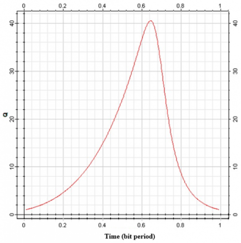
Figure 3. Signal quality factor due to DWDM effect
Signal quality factor (Q-Factor) with the DWDM effect: The maximum value of the Q-factor of 40.5271 indicates exceptionally high signal quality in the optical network, as shown in Figure 3. A higher Q-factor indicates excellent system performance with a strong signal-to-noise ratio, resulting in reliable data transmission and minimal errors. It is a positive indication of the network's ability to handle dense wavelengths effectively.
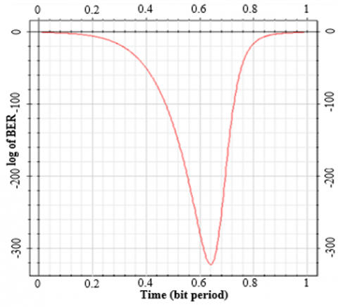
Bit error rate (BER) due to DWDM: The smallest BER value indicates that using DWDM achieves error-free transmission, as shown in Figure 4. A bit error rate of almost zero indicates no bit errors during data transmission. It is a very robust and reliable communication system. It is an excellent result, highlighting the network's ability to maintain high-quality signal transmission across multiple wavelengths.
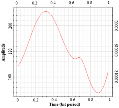
Threshold value with DWDM effect: The threshold value 0.0175413 represents the decision limits for bit detection in the optical network. A low threshold value indicates that the system has high sensitivity to signal strength levels, as shown in Figure 5, enabling it to detect even weak signals or signals with low energy. A low threshold can be beneficial in achieving accurate bit detection and reducing errors, especially in a DWDM system with several channels nearby.
Figure 4. BER due to DWDM effect
Figure 5. Threshold value due to DWDM effect
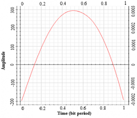
Figure 6. Eye height due to DWDM effect
Eye height due to DWDM effect: The measured eye height of 0.0294991 indicates a relatively large vertical distance between the highest and lowest points of the eye chart, as shown in Figure 6. A high eye height shows that the received signals have a large margin above the noise floor, enabling reliable bit detection and improved resistance to attenuation. It is a positive sign, indicating good signal quality and sufficient signal strength, even with densely packed DWDM channels.
Overall, the presented results indicate a high-performance optical network using DWDM technology. It has a high Q factor, an error rate close to zero, a high eye height, a low threshold, and a well-defined decision point. The network demonstrates excellent signal quality, robustness, and reliable data transmission capabilities, even with the challenges posed by densely packed DWDM channels.
The optical fiber network was designed and simulated. The effect of high voltage electrical wires on it was demonstrated. This network was designed to suit the geographical area of Mosul city. The length of the proposed network is 4683 meters. From the simulation results, the following can be seen:
The optical signal is affected by the magnetic field resulting from the high voltage when it is in the same direction.
The influence of the magnetic field (Kerr or Faraday) leads to a deterioration in the value of the Q factor and an increase in the bit error rate for the optical signal.
Using the phase corrector on the receiving side, the field effect is reversed, the Q-factor value is improved, and the bit error rate is reduced. Thus, the original signal required is restored with the data arriving correctly.
Simulation results indicate that the effect of the magnetic field on the optical signal is very small and within acceptable limits with regard to the current frequencies, but it may become a problem with the development of working frequencies later.
The quality of the proposed design of the optical network with good performance using DWDM technology.
Currently, work is underway to study the change of results using optical signal amplifiers.
|
B |
Magnetic field density, m.s-2 |
|
D |
The length of the path of interaction between the light and the magnetic field, m |
|
E |
Electric field intensity |
|
H |
The magnetic field intensity |
|
WDM |
Wavelength division multiplexing, K-1 |
|
Greek symbols |
|
|
Β |
The rotation angle, degree |
|
Θ |
Verdt constant |
|
Λ |
Wavelength, m |
|
Subscripts |
|
|
VH0 |
Verdet's H-field matter constant for rotation polarization |
|
λK |
Kerr coefficient |
|
μ0 |
Vacuum permeability |
[1] Garcia, S., Gasulla, I. (2020). Universal characteristic equation for multi-layer optical fibers. IEEE Journal of Selected Topics in Quantum Electronics, 26(4): 4300111. https://doi.org/10.1109/JSTQE.2020.2996375
[2] Alsharbaty, F.S., Ayoob, S.A. (2019). Intra-site CoMP operation effect of fifth generation techniques on 802.16 e downlink stream. International Journal of Engineering Trends and Technology, 67(4): 12-17. https://doi.org/10.14445/22315381/IJETT-V67I4P204
[3] Khalil, H., Qamar, F., Shahzadi, R., Shahzad, A., Ali, M., Qamar, N., Al-Otaibi, S. (2021). Performance analysis of modulation formats for next generation RoF systems. IEEE Access, 9: 139393-139402. https://doi.org/10.1109/ACCESS.2021.3116351
[4] Ayoob, S.A., Alsharbaty, F.S., Hammodat, A.N. (2023). Design and simulation of high efficiency rectangular microstrip patch antenna using artificial intelligence for 6G era. TELKOMNIKA (Telecommunication Computing Electronics and Control), 21(6): 1234-1245. http://doi.org/10.12928/telkomnika.v21i6.25389
[5] Ahmed, S.A., Ayoob, S.A., Al Janaby, A.O. (2021). On the performance of multi-user massive MIMO over mm wave channels. In 2021 7th International Conference on Contemporary Information Technology and Mathematics (ICCITM), Mosul, Iraq, pp. 100-105. https://doi.org/10.1109/ICCITM53167.2021.9677730
[6] Hussein, R.A., Ayoob, S.A. (2021). Performance analysis of NOMA using different types receivers. In 2021 4th International Conference on Information and Communications Technology (ICOIACT), Yogyakarta, Indonesia, pp. 131-136. https://doi.org/10.1109/ICOIACT53268.2021.9563918
[7] Dreifuerst, R.M., Heath, R.W. (2023). Massive MIMO in 5G: How beamforming, codebooks, and feedback enable larger arrays. IEEE Communications Magazine, 61(12): 18-23. https://doi.org/10.1109/MCOM.001.2300064
[8] Abed, R.A., Ayoob, S.A. (2023). Millimeter wave beams coordination and antenna array height effect. AIP Conference Proceedings, 2830(1): 040003. https://doi.org/10.1063/5.0157290
[9] Hammodat, A.N., Ayoob, S.A. (2021). Studying the effect of increasing capacity using comp technology in LTE-A networks. Journal of Engineering Science and Technology, 16(1): 556-570.
[10] Esmail, M.A. (2023). Performance monitoring of hybrid all-optical fiber/FSO communication systems. Applied Sciences, 13(14): 8477. https://doi.org/10.3390/app13148477
[11] Senior, J.M., Jamro, M.Y. (2009). Optical Fiber Communications: Principles and Practice. Pearson Education.
[12] Taha, T.A., Ayoob, S.A., Yaseen, M.T. (2023). Raman/EDFA hybrid system to enhance the optical signal in the optical network. Journal of Communications, 18(10): 621-628. https://doi.org/10.12720/jcm.18.10.621-628
[13] Amrane, S., Zahidi, A., Abouricha, M., Azami, N., Nasser, N., Errai, M. (2021). Machine learning for monitoring of the solenoid valves coil resistance based on optical fiber squeezer. Journal Européen des Systèmes Automatisés, 54(5): 763-767. https://doi.org/10.18280/jesa.540511
[14] Keiser, G. (2000). Optical Fiber Communications (Vol. 2). New York: McGraw-Hill.
[15] Supe, A., Porins, J. (2012). Interaction between electromagnetic field and optical signal transmission in fiber optics. Elektronika ir Elektrotechnika, 122(6): 83-86. https://doi.org/10.5755/j01.eee.122.6.1826
[16] DeCusatis, C. (2002). Fiber Optic Data Communication: Technology Advances and Futures. Academic Press.
[17] Liu, F., An, Y., Wang, P., Shao, B., Chen, S. (2012). Effects of radiation on optical fibers. In Recent Progress in Optical Fiber Research, pp. 431-450.
[18] da Silva, A.A.D., Alves, H.P., Marcolino, F.C., do Nascimento, J.F., Martins-Filho, J.F. (2020). Computational modeling of optical fiber-based magnetic field sensors using the Faraday and Kerr magnetooptic effects. IEEE Transactions on Magnetics, 56(9): 1-9. https://doi.org/10.1109/TMAG.2020.3010108
[19] Royer, F., Varghese, B., Gamet, E., Neveu, S., Jourlin, Y., Jamon, D. (2020). Enhancement of both Faraday and Kerr effects with an all-dielectric grating based on a magneto-optical nanocomposite material. ACS Omega, 5(6): 2886-2892. https://doi.org/10.1021/acsomega.9b03728
[20] Lofy, J., Gasparian, V., Gevorkian, Z., Jódar, E. (2020). Faraday and Kerr effects in right and left-handed films and layered materials. Reviews on Advanced Materials Science, 59(1): 243-251. https://doi.org/10.1515/rams-2020-0032
[21] Yao, P., Chen, X., Hao, P., Xiao, H., Ding, Z., Liu, T., Yao, X.S. (2021). Introduction and measurement of the effective Verdet constant of spun optical fibers. Optics Express, 29(15): 23315-23330. https://doi.org/10.1364/OE.432418