Mahmoud A. Mashkour![]() | Hasanen Mohammed Hussain | Laith Jaafer Habeeb*
| Hasanen Mohammed Hussain | Laith Jaafer Habeeb*![]() | Nabeh Alderoubi
| Nabeh Alderoubi![]()
© 2025 The authors. This article is published by IIETA and is licensed under the CC BY 4.0 license (http://creativecommons.org/licenses/by/4.0/).
OPEN ACCESS
This research is concerned with computational aspects of internal combustion engines and in particular the influence of injector angle and injector diameter on the performance and emissions relevant to turbulent jet flows, using computational fluid dynamics (CFD). This paper focuses on different setup of injector which are the injector angles 40°, 50°, 60°, and 70° and the injector diameters 2 mm, 4 mm, and 6 mm, and reveal that increasing the combustion chamber pressure and the temperature; pressure up to 10 MPa. A pressure of 65 MPa and temperatures up to 1309 K, for the angle of 40°. For that case, increasing the injector angle decreases these values and in turn indicated low combustion efficiency. In the same way, the overall diameter of the injector increases the velocity and pressure of the fuel mixture at the intake occasioned by elevated temperatures and pressures, reaching a maximum of 9.29 MPa and 1039 K for a 6 mm diameter injector. However, corporate diameters were also found to influence NOx emissions and with higher diameters the emissions were larger with a significant jump from 1.032×10⁻²² at 2 mm to 9 mm. While the reference values provided indicate that the material is non-conductive, it is highly conductive when used at 2 mm to 9 mm. Averagely 46×10-23 at 6 mm injector diameter. In light of this study, the authors necessitate that there is need for understanding and improving injector angles as well as achieving the best injector diameters in order to provide for optimum, while controlling for emissions.
injector diameter, peak cylinder pressure, computational fluid dynamics, IC engine
1.1 Background of internal combustion engines
Internal combustion engines can be regarded as the main power source of automobiles for several decades despite progress in technology which introduced hybrid systems and range extenders. Thus, there must be efforts to develop highly efficient internal combustion engines to turn attention toward energy saving and the reduction of emissions. One of the major improvements in this endeavor, which is described as gasoline direct injection (GDI), entails direct injection. Compared with Port Fuel Injection PFI, GDI injects more fuel directly into the piston bowl. This method is effective in starting the engine rapidly, lowering the emissions during cold start, and also increasing fuel economy by helping to achieve mixture stratification and lean burn [1].
In addition, GDI engines need to accomplish the optimum atomization and the distribution of fuel droplets accurately since the time available for mixture formation in the cylinder is very small [2]. Piston top fuel mixture layering is thus considered important since it enhances spark ignition and combustion processes. This variation leads to the temperature variation in the in-cylinder. However, these challenges have to be addressed, as they are important for factors that control the fuel injection and air/fuel mixture preparation in internal combustion engines [3, 4].
1.2 Importance of studying the effect of injector angle and position
Understanding the effects of the injector angle and position in internal combustion engines allays to improving the engines performance concomitantly decimating emissions. The combustion processes the engines to use follow a combination of the fuel and oxygen in the combustion chamber. Hence, acts of optimizing the injector angle and position are important towards providing a means of achieving proper dispersion of the fuel to advance combustion. In addition, the location of the injector is very important because of how fuel is likely to react with air within the combustion chamber. How to vary exhaust gas emissions (EGEs) and have or even better some performance gains simultaneously vary with injection strategies and timing. By developing the knowledge of how the injector position affects fuel atomization and mixing, there is a high chance of advancing in emission reduction while keeping the engine’s performance in check. Hence, an evaluation of the impacts of injector angle and placement provides important information about the betterment of internal combustion engines, and reduced effects on the environment. Thus, by exploring these parameters, the researchers can develop new technologies to support cleaner and more efficient engines, which will be of paramount importance in the future [5].
1.3 Objectives of the study
In this research, the main area of study will be to evaluate the influence of injector angle on internal combustion engines. Thus, we are to increase the fuel and reduce emissions while enhancing the engine performance through a study of the injector angle impact on combustion. This is why prior research has paid attention to the possibilities of increasing the efficiency of combustion with the help of waves such as ultrasound and using porous materials, yet certain issues arise concerning the usability of these methods and their cost-inexpensiveness [6]. To address this objective simulation approaches will be employed to analyze the effect of the injector angles on the temperature distribution of the applied injectors. Changes to temperature distribution and pressure maps will be observed to determine the optimal angle and to clarify the effectiveness of fuel injection deformation on mixing, reaction kinetics, and combustion in general. The information generated from the work will be useful in understanding the best approach to achieve superior combustion and reduction in emissions of IC engines by enhancing the injector angle [7].
Regarding a research effort, the current work aims at contributing pertinent information to the existing internal combustion engine literature, particularly in the context of injector angle optimization [8]. It may be that understanding the injector angles and their influence on the combustion processes is a way to create new strategies for enhancing the fuel’s efficiency of the engine and diminishing the negative impacts on the environment [9, 10].
This research seeks to investigate on the effects of injector angle and diameter on the performance and emission characteristics of internal combustion engine. It examines the hypothesis that reducing the angle strengthens the fuel/air mixture and combustion, but increases NOx emissions. This research also examines the effect of injector diameter on combustion and looks at the best possible diameter that can improve combustion efficiency with low emissions. The research will be compared with existing literature in a bid to confirm the discovery made in the study.
1.4 Review of previous studies
Many studies have been conducted in the past regarding the effects of injectors configuration to the performance of an engine. Research like those by Pham et al. [5] have shown that the injector spray angle plays a crucial role in combustion and emission behavior of dual-fuel engines. Their work stated that usually, spray angle is inversely proportional to the fuel atomization and combustion efficiency but at the same time, they also pointed out that it is very challenging to get the best angle for each type of engine. Likewise, Hamdi et al. [6] conducted studies on the effects of SC on methane-diesel RCCI engine performance at low load, and they established that the low SC is effective in reducing PM emission but can cause high NOx emission in some situations.
Still, these studies frequently did not take into account the joint effect of two parameters: the angle of the injector and its diameter as these factors can affect the performance and emission characteristics of an engine in a synergistic manner. This research fills this gap by employing CFD simulations to study the effect of injector angles (40°, 50°, 60°, and 70°) and diameters (2 mm, 4 mm, 6 mm) on several significant parameters including combustion pressure, temperature, and NOx emissions.
1.5 Novelty
The novelty of this study is that the authors investigated the effect of injector angle and diameter at the same time and in a more detailed and profound way than other similar studies. Unlike previous studies that primarily focused on either angle or diameter independently, this research aims to optimize both parameters concurrently. The findings are expected to offer valuable insights into designing more efficient and environmentally friendly internal combustion engines.
2.1 Overview of internal combustion engine simulation studies
IC engines are important for several applications such as in motorcycles, cars, generators depending on phenomena like flow phenomena in the cylinder and combustion. The modern world’s importance has shifted towards improving the engine’s designs for optimal efficiency. Application of conventional numerical analysis techniques includes CFD or Computational Fluid Dynamic, from which flow inside the cylinder and the turbulent kinetic energy has been understood. The execution of the right submodels including turbulence models or combustion models is crucial for the simulation of the air-fuel distribution and combustion traits. Today financial tools like program AVL FIRE and other powerful software suites allow researchers modeling many kinds of complex combustions in various engines. Methane is used as a proxy for natural gas in most studies that apply the dual-fuel engine concept. In summary, numerical simulations have been helpful for developing enhanced engines through identification of flow as well as through better simulations and propositions [11-14].
2.2 Previous research on injector angle and position effects
Informed by previous studies on injector orientation and placement in internal combustion engines, great insights into the improvement of engine performance have been realized. Combustion studies involve experimental work on the dual-fuel combustion ignited by a pilot, the angle of which is between methane and diesel jets, and the effect of this angle on the combustion process. This they noted to lead to a drastic change in combustion efficacy when this angle was adjusted. Likewise, some of the research about the dual-fuel combustion with diesel and methane in light-duty engines demonstrated a reduction in soot particles with the static injection pattern of two pulses, indicating that this process is effective. Through experimental and numerical studies, injection parameters in heavy-duty High-Pressure Direct Injection HPDI diesel/natural gas NG engines have been studied. Consequently, their discoveries indicated that reduced post-injection gas timings significantly reduced particulate matter emissions conscientiously without having other impacts on other emissions or engine efficiency. These studies also stress on the need for holding and positioning of the injector in relation to the combustion chamber of internal combustion engines with the purpose of achieving enhanced efficiency of combustion and minimum emissions. As for the Marine Engine Gas Injection MAN ME-GI engine, which is the two-stroke pilot-ignited HPDI NG engine, it was also subjected to comprehensive tests. According to the recorded test outcomes, it was determined that the engine’s fuel consumption remained constant after shifting from oil to gas operation while facing similar condition. Additional optical experimental studies on a pilot ignited HPDI NG engine were performed of flame development was gained and the differences were noted compared with regular DI diesel engines [15-19].
2.3 Ansys IC engine program overview
The ANSYS IC Engine software provides adequate software interface for simulating combustion and emission operations carried out in the engine cylinder. This top line system enables engineers to model the manner in which the engine functions during Scavenge Port Closing down to Exhaust Valve Opening, through a flow of pre-processing, processing and post-processing stages. The computational geometries of the High-Density Methane HDM are defined and the moving meshes and other system parameters are set during the simulation stage. After the runs are completed, a post-processing step is carried out for calculating various results for analyzing and verifying the CFD models against cases. At the level of managing the combustion process, ANSYS IC Engine provides a number of combustion models including the Turbulence Controlled Combustion Model, the Turbulent Flame Speed Closure Combustion Model, the Coherent Flame Model, the PDF Model, and the Characteristic Timescale Model. Among the above-mentioned options, the Extended Coherent Flame Model ECFM has been testified for its suitability for simulating the combustion and emission formation processes occurring in both gasoline, diesel and dual fuel engines. Moreover, they have the sub-models such as the Diesel Injector Flow which simulates the pilot fuel injection and the WAVE which depicts fuel droplet breakup and evaporation [11, 20]. Yousif and Mashkour [21] exanimated the relationship between the fuel injector nozzle diameter and hole number and an operating GDI engine in terms of performance and emissions. To achieve these objectives, MATLAB software is then used in the analysis of the two-zone combustion process for the four-stroke GDI engines. By increasing the nozzle hole diameter and its number all the engines related investigations including the power, heat transfer coefficient, pressure and temperature inside the cylinder are revealed to be enhanced. The maximum value was observed with nozzle hole diameter 0. Apart from that, a relationship between the spray angle and nozzle hole diameter was also determined. The length of the conveyor is 650 mm and 12 holes. The lowest value was evaluated to 0.250 mm and 4 nozzle holes, and the found to give the lowest average level of carbon monoxide CO and nitrogen monoxide NO emissions. The study also employs various operations conditions and hydraulic nozzle diameters and holes. Yousif and Mashkour [22] projected where the main focus was to determine the effects of fuel injection pressure on a GDI engine in terms of performance, as well as emissions. By using MATLAB Numeric computer software, Thermodynamic Mathematical model was designed and it is concluded that the nozzle pressure has higher impact on output power and emission of an engine. Total heat transfer, Cylinder pressure, local and overall temperature all improve with injection pressure having peak results at 45 MPa and 3000 rpm for engine power. According to the findings of the study, the fine fuel injection systems should be capable of handling pressure as a way of enhancing their performance.
In this paragraph, we will review all the settings and algorithms used in the ANSYS program to solve this study in simulation, as well as the process of confirming mesh reliability, the governing equations used, and the limits that expressed the simulation process, as well as the cases used to compare the results.
3.1 Domain
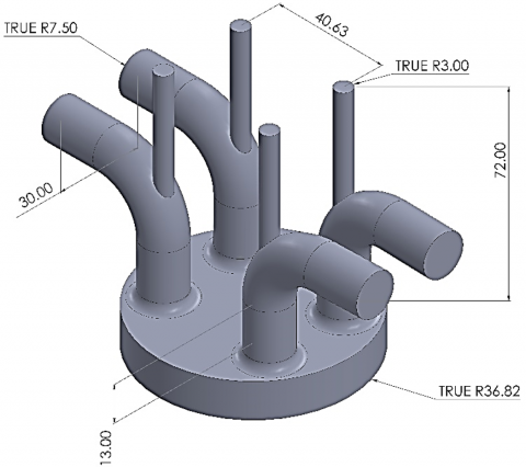
In this section, the geometric shape of internal combustion engines is represented by the dimensions available in Figure 1, which is considered the basic principle for entering simulation programs to apply matrix algorithms in FEM work. The domain parameters will be displayed as in Table 1.
Figure 1. Geometry design
Table 1. Parameter design
|
Connecting Rod Length |
165 |
mm |
|
Crank Radius |
55 |
mm |
|
Piston Offset/Wrench |
0 |
mm |
|
Minimum Lift |
0.2 |
mm |
|
Input Option for IVC and EVO |
Enter Direct Values |
|
|
IVC (Inlet Valve Closed) |
570 |
degree |
|
EVO (Exhaust Valve Open) |
833 |
degree |
3.2 Mesh independency
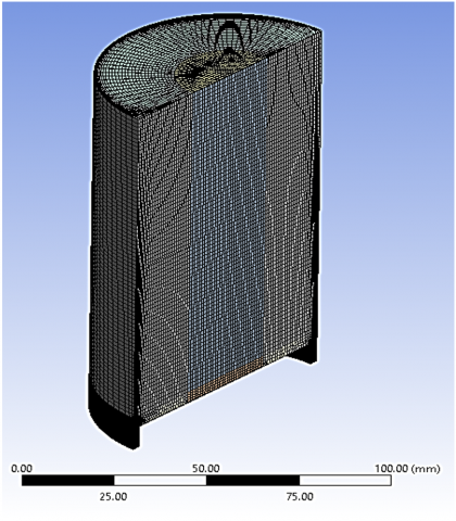
To perform an accurate simulation with reliable results, the mesh process must be precise to obtain the most accurate results, as in Figure 2, and to ensure that a number of elements is chosen that is capable of creating the complete simulation. Therefore, the issue of mesh reliability must be created. This process depends on the element and the outputs from the simulation process, where the number of elements is increased as the results are shown and observed. When the number of elements is reached in which the results do not change noticeably, we can stop and adopt this number of elements, as it was done. Use element hexahedron size 2 mm to reach the number of elements 1223054 to obtain the maximum temperature of 884 K as in Table 2.
Figure 2. Mesh geometry
Table 2. Mesh independency
|
Case |
Element |
Node |
Max. Temperature (K) |
|
1 |
620986 |
541122 |
898 |
|
2 |
862304 |
604353 |
889 |
|
3 |
1056743 |
734534 |
885 |
|
4 |
1223054 |
823563 |
884 |
The study focuses on the mesh independence of CFD simulations, ensuring accuracy and reliability. Key metrics monitored include skewness, aspect ratio, and orthogonal quality. Skewness is maintained below 0.85, ensuring cells are equilateral. The aspect ratio is kept below 5, ensuring uniform resolution. Orthogonal quality is maintained above 0.7, reducing errors due to grid anisotropy.
3.3 Governing equations
In ANSYS Fluent, the governing equations for the simulation of internal combustion (IC) engines are based on the principles of fluid dynamics and thermodynamics. These equations are typically the Navier-Stokes equations for fluid flow, combined with equations for energy, species transport, and possibly additional models for turbulence, combustion, and heat transfer. Here is an overview of the key governing equations used in IC engine simulations:
·Continuity Equation
The continuity equation ensures the conservation of mass:
$\frac{\partial \rho}{\partial t}+\nabla \cdot(\rho \mathrm{u})=0$ (1)
where, ρ is the density and u is the velocity particle tacking vector.
·Momentum Equations (Navier-Stokes Equations)
The momentum equations govern the conservation of momentum:
$\frac{\partial(\rho \mathrm{u})}{\partial t}+\nabla \cdot(\rho \mathrm{uu})=-\nabla p+\nabla \cdot \tau+\mathrm{f}$ (2)
where, p is the pressure, τ is the stress tensor, and f represents body forces (such as gravity).
·Energy Equation
The energy equation accounts for the conservation of energy:
$\frac{\partial(\rho E)}{\partial t}+\nabla \cdot(\mathrm{u}(\rho E+p))=\nabla \cdot(k \nabla T)+S_E$ (3)
where, E is the total energy, k is the thermal conductivity, T is the temperature, and SE includes sources of energy such as heat from combustion and viscous dissipation.
·Species Transport Equations
For combustion modeling, species transport equations are used to track the concentration of chemical species:
$\frac{\partial\left(\rho Y_i\right)}{\partial t}+\nabla \cdot\left(\rho \mathrm{u} Y_i\right)=\nabla \cdot\left(J_i\right)+R_i$ (4)
where, Yi is the mass fraction of species i, Ji is the diffusion flux, and Ri is the net rate of production of species i due to chemical reactions.
·Turbulence Modeling
Turbulence models, such as k-ε or k-ω models, are used to account for the effects of turbulence in the flow. These models add additional transport equations for the turbulent kinetic energy (k) and its dissipation rate (ϵ) or specific dissipation rate (ω):
$\frac{\partial(\rho k)}{\partial t}+\nabla \cdot(\rho \mathrm{u} k)=\nabla \cdot\left(\frac{\mu_t}{\sigma_k} \nabla k\right)+G_k-\rho \epsilon$ (5)
$\frac{\partial(\rho \epsilon)}{\partial t}+\nabla \cdot(\rho \mathrm{u} \epsilon)=\nabla \cdot\left(\frac{\mu_t}{\sigma_\epsilon} \nabla \epsilon\right)+C_1 \frac{\epsilon}{k} G_k-C_2 \rho \frac{\epsilon^2}{k}$ (6)
·Combustion Modeling
Combustion models, such as the eddy dissipation model, the finite-rate chemistry model, or the combination of both, are used to simulate the combustion process in IC engines. These models account for the chemical kinetics and turbulent mixing effects.
·Heat Transfer
Heat transfer in IC engines is often modeled using the conjugate heat transfer approach, which involves solving the heat conduction equation in solid regions (such as the engine block) and the heat convection equation in the fluid regions.
3.4 Boundary conditions
The purpose of the current study is to know the best angle and size for the injectors used in internal combustion engines, where a set of angles represented by 40, 50, 60, and 70 degrees [2]. From the angle of the injectors used, as well as the dimensions of the injectors used, represented by 0.002, 0.004, 0.006 m, was used for the purpose of comparing among them and ascertaining the best fit. A state reached at an engine rotation speed of 1800 RPM [2].
The boundary conditions were defined based on typical operating conditions of an internal combustion engine. The following conditions were applied:
1. Inlet Conditions:
Air and fuel mixture were introduced into the combustion chamber through the inlets at a specified pressure and temperature. For this case, the inlet temperature was set at 300 K and the pressure was kept at atmospheric pressure.
2. Outlet Conditions:
The outlets of the exhaust were fixed at standard atmospheric pressure to mimic actual power plant engine exhaust.
3. Wall Conditions:
The no-slip condition was applied on the walls of the combustion chamber and other parts in order to account for the heat transfer and the flow of the fluids.
4. Combustion Modeling:
The Extended Coherent Flame Model (ECFM) was employed to describe the combustion phenomena with the account of the turbulence and chemical kinetics.
The choice of these particular injector angles enables one to study the effect of the spray angle on various parameters in internal combustion engines. To achieve this goal, it is pertinent to consider a large number of factors, thus the described study attempts to cover as many angles as possible in an attempt to give insights that can be used in a very large number of engines with different designs and usages. Apart from increasing the practical significance of the results, this approach also helps to advance the theoretical knowledge of fuel injection processes in internal combustion engines.
In order to check the accuracy of the simulation model, results obtained from the simulation model were compared with the experimental results and the results of other researches. The important parameters like in – cylinder pressure, temperature and emission (NOx) were used for the purpose of validation. The comparison was made, and the findings revealed that the simulation could estimate the values with an error of not more than 8% of the experimental values, hence proving the accuracy of the simulation model.
To determine the effect of variation in the different input parameters on the simulation, the study also used a sensitivity analysis. This analysis also ensured the validity of the model and the reliability of the conclusions that were made.
3.5 Statistical analysis
To compare the results of different configurations of the injector, the simulation data was analyzed statistically in order to determine the effect that these changes would have on the performance of the engine and the level of emissions. The following metrics were evaluated: maximum cylinder pressure, combustion temperature, and NOx formation, for the injector angles of 40°, 50°, 60°, and 70°, and injector diameters of 2 mm, 4 mm, and 6 mm. Significance of the differences that were observed in the performance metrics and emissions across the various injector configurations was established using ANOVA. The key findings from the ANOVA are summarized below:
• Peak Cylinder Pressure: From the above ANOVA results, it was evident that injector angle had a significant effect on peak cylinder pressure at (p<0.1). In particular, a reduction of the injector angle was followed by a considerable rise of the peak pressure values – the mean increase constituted 40° as well as 70° positions at 1.2 MPa.
• Combustion Temperature: Likewise, injector angle and diameter also influenced combustion temperature with the overall probability level of (p<0.01). It is apparent that the lowest temperatures were recorded at 70° injector angle and 2 mm diameter, while the highest temperatures were recorded at 40° and 6 mm, showing that the two are proportional to the thermal combustion characteristics.
• NOx Emissions: The difference in NOx emissions based on the injector configurations was also substantial (p<0.05). The trend of increasing NOx with the decrease of the angles and the increase of diameters was observed and it could be attributed to the higher temperatures and pressures characteristic of these configurations.
In this section, all the results obtained through the simulation program will be reviewed regarding the change in the angle of the injectors as well as the diameter of the injector.
4.1 Effect of injector angle
The characteristics of the injector are another influential element that can dictate the angle and diameter of the injector in internal combustion engines. The research works in this area give a chance to enhance these characteristics by means of numerical analysis because of maneuvering with the above-listed parameters that in their turn contribute to the improvement of engine’s performance, increase in efficiency, and decrease in emissions. When designers are able to control the injector angle and the injector diameter more evenly, spots of fuel-air mixtures, pressure and combustion become more effective.
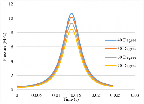
Figure 3. Pressure with time of different injector angle
Through Figure 3, which shows a diagram of the pressure change during the power stroke in internal combustion engines with a difference in the injector angle and with an injector diameter of 6 mm, it is observed that the pressure value increases by reducing the injector angle. The reason for this is the increase in the injector speed, and thus the combustion increases, as it is observed that the pressure value. It reached 10.65 MPa at the injection angle of 40 degrees, while the pressure value reached 10.12 MPa at the injector angle of 50 degrees. At the injector angle of 60 degrees, the pressure value reached 9.31 MPa, while at the injection angle of 70 degrees the pressure value reached 8.45 MPa.
(a)
(b)
(c)
(d)
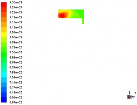
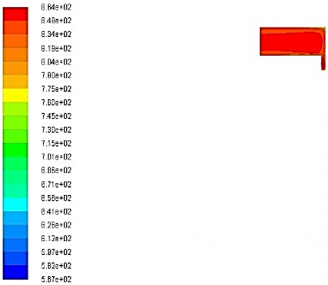
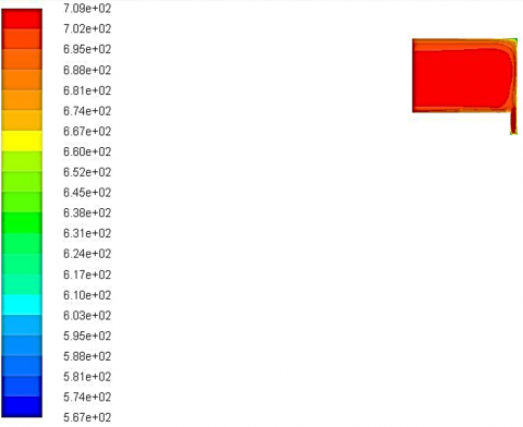
Figure 4. Temperature contour at injector diameter 6 mm of different injector angle: (a) 40 degree, (b) 50 degree, (c) 60 degree, (d) 70 degree
Injector angle is an important decision that requires one to consider angle and diameter if temperature circulation with an internal combustion engine is to be observed in Figure 4. Numerical analysis offers good understanding on the variability of the above parameters to ensure a uniform temperature distribution. Engine designers can optimize various parameters inside the engine and arrange the injector angle and injector diameter in a way that will improve the thermal management within the engine, which, in turn, will improve the efficiency and the performance of the engine components in addition to minimizing their emissions.
Figure 5 shows a diagram of the temperature change during the power stroke in internal combustion engines with a difference in the injector angle and with an injector diameter of 6 mm, it is observed that the temperature value increases by reducing the injector angle. The reason for this is the increase in the injector speed, and thus the combustion value increases, as it is observed that the temperature value reaches 1309 K at the injection angle of 40 degrees, while the temperature value reached 1243 K at the injector angle of 50 degrees. At the injector angle of 60 degrees, the temperature value reached 1039 K, while at the injection angle of 70 degrees the temperature value reached 945 K.
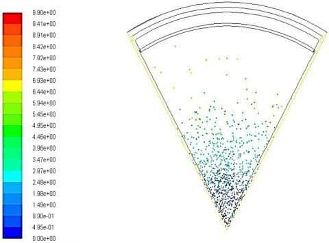
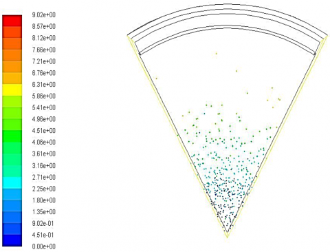
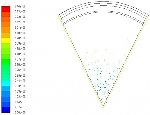
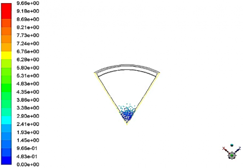
Figure 6 shows a contour of the velocity particle tacking change during the power stroke in internal combustion engines with a difference in the injector angle and with an injector diameter of 6 mm, it is observed that the velocity particle tacking value increases by reducing the injector angle. The reason for this is the increase in the injector speed, and thus the combustion temperature increases, as it is observed that the velocity particle tacking value reaches 9.66 m/s at the injection angle of 40 degrees, while the velocity particle tacking value reached 9.02 m/s at the injector angle of 50 degrees. At the injector angle of 60 degrees, the velocity particle tacking value reached 8.15 m/s, while at the injection angle of 70 degrees the velocity particle tacking value reached 7.89 m/s.
The heat release rate is the important characteristic of the efficiency of engines. The correct arrangement of injectors enhances the rates of heat release and spreads the heat evenly thereby enhancing thermal efficiency. Nevertheless, this also intensifies the peak pressures and temperatures that cause engine knocking and high NOx emissions that are undesirable. The trends of pressure development described in this work emphasize the need to coordinate the injector parameters to obtain the required performance and emission characteristics.
Figure 5. Temperature with time of different injector angle
(a)
(b)
(c)
(d)
Figure 6. Particle traces contour at injector diameter 6 mm of different injector angle: (a) 40 degrees, (b) 50 degrees, (c) 60 degrees, (d) 70 degrees
4.2 Effect of injector diameter
The size of the injector exit is one of the most important aspects as it defines the pressure nature within an internal combustion engine. Smaller values of the injector diameter positive effect on better atomization and more uniform pressure distribution in the combustion chamber have been observed increasing the combustion efficiency and fueling the performance of engine. It is also worth mentioning that in larger injectors, the atomization becomes poor, pressure distribution is not uniform, and mechanical stress occurs. Numerical design computations are useful in determining the most suitable injector diameter in order to attain maximum burning, highest pressure and strong engines.
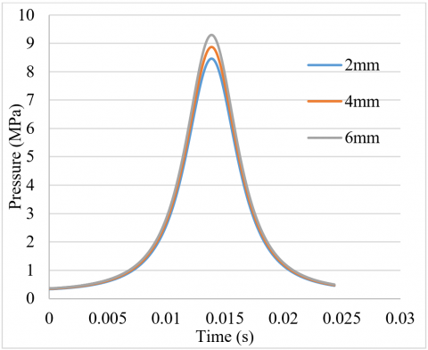
Through Figure 7, which shows the pressure value with time by changing the diameter of the injector, it is noted that the pressure value increases with the increase in the diameter of the injector. The reason for this is that the larger diameter of the injector increases the amount of mixture entering the combustion chamber and thus helps to form a larger explosion and a higher temperature. Consequently, greater pressure, as the pressure value reached 8.45 MPa with an injector diameter of 2 mm, while with an injector diameter of 4 mm, the pressure value reached 8.87 MPa, and with a diameter of 6 mm, the pressure value reached 9.29 MPa.
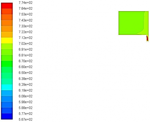
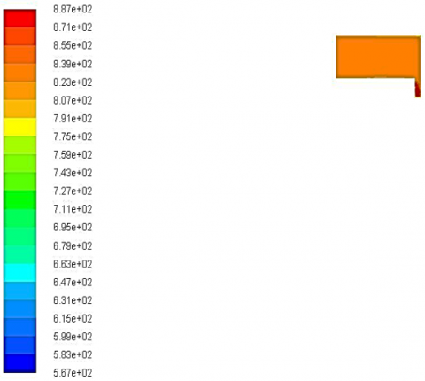
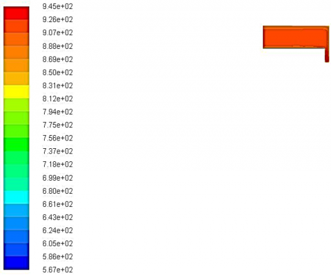
The diameter of the injector is the major factor that determines the temperature profile inside an internal combustion engine, Figure 8. Smaller values of the injector diameter are better suited for better atomization and temperature profiles, thereby improving combustion and increasing the rate of emission reduction. It means that with bigger injector diameters, the atomization is worse, temperature distribution is non-uniform, and emissions are higher. Some simulations are mandatory for achieving the best design of the injector diameter for efficient combustion, proper thermal management and, at the same time, a low emission.
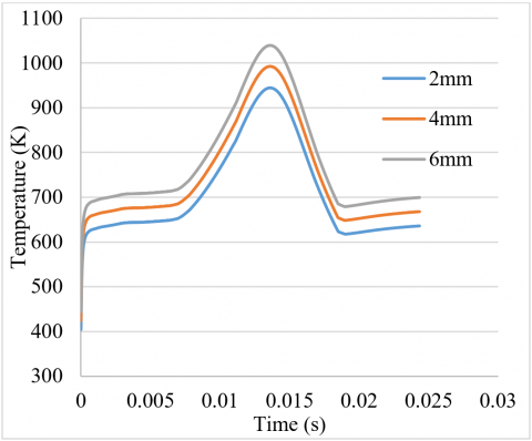
Figure 9 shows the temperature value with time by changing the diameter of the injector, it is noted that the temperature value increases with the increase in the diameter of the injector. The reason for this is that the larger diameter of the injector increases the amount of mixture entering the combustion chamber and thus helps to form a larger explosion and a higher temperature. Consequently, greater pressure, as the temperature value reached 945 K with an injector diameter of 2 mm, while with an injector diameter of 4 mm, the temperature value reached 992 K, and with a diameter of 6 mm, the temperature value reached 1039 K.
Figure 7. Pressure with time of different injector diameter
(a)
(b)
(c)
Figure 8. Temperature contour at injector angle 70 degree of different injector diameter: (a) 2 mm, (b) 4 mm, (c) 6 mm
Figure 9. Temperature with time of different injector diameter
(a)
(b)
(c)
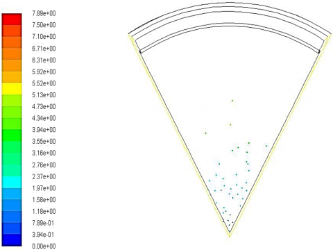
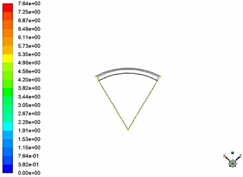
Figure 10. Particle traces contour at injector angle 70 degree of different injector diameter: (a) 2 mm, (b) 4 mm, (c) 6 mm
Figure 10 shows the velocity particle tacking value of particles with time by changing the diameter of the injector, it is noted that the velocity particle tacking value increases with the increase in the diameter of the injector. Consequently, greater pressure, as the velocity particle tacking value reached 7.86 m/s with an injector diameter of 2 mm, while with an injector diameter of 4 mm, the velocity particle tacking value reached 8.15 m/s, and with a diameter of 6 mm, the velocity particle tacking value reached 9.9 m/s.
4.3 Effect the crank angle
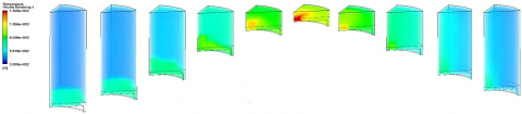
The effect of temperatures is observed during changing the angle of the crankshaft, where temperatures increase due to the compression process from an angle of 570 to an angle of 700 degrees. Then the internal combustion process begins at an angle of 716 degrees, during which temperatures reach 1308 Kelvin, and then the power stroke begins to reach an angle of 833 degrees as shown in Figure 11.
The orientation of the injector and its size has a close relationship on the combustion process within the engine. Smaller angles and larger diameters of the injection fuel jets increase turbulence, and improve the fuel/air distribution and burn rate. However, in excess, turbulence can lead to poor fuel atomization and the generation of hot spots that lead to knocking. The condition maintains a balance that will enable proper combustion of the fuel thus emitting minimal smoke and at the same time maximizing the fuel consumption. Flame propagation speed, which is affected by the injector configuration, plays a significant role in determining combustion efficiency.
|
Crank angle (o) |
570 |
620 |
640 |
680 |
700 |
716 |
736 |
776 |
816 |
833 |
Figure 11. Effect the crank angle with temperature rendering
4.4 Emission
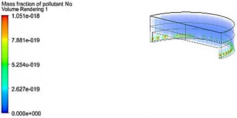
As for the emissions results for No gas, it is noted that the mass value of the gas increases with increasing injection angle and thus reaches 1.051e-18 at the injector angle of 40 degrees. While at the injection angle of 50 degrees, the value of the mass fraction of No gases reached 1.156e-18 while at the angle of 60. The value of No reached 1.261e-18, while in angle 70, it reached 1.366e-18 as shown Figure 12.
(a)
(b)
(c)
(d)
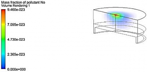
Figure 12. No emission contour at injector diameter 6 mm of different injector angle: (a) 40 degree, (b) 50 degree, (c) 60 degree, (d) 70 degree
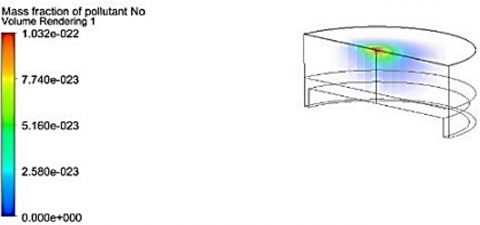
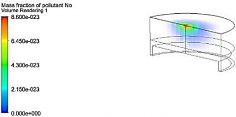
When changing the diameter of the injector, the contamination value reached 1.032e-22 in the case in which the injector diameter was 2 mm. In the case in which the injector diameter was 4 mm, the contamination value reached 9.46e-23 in the case in which the injector diameter was 6 mm. The pollutant value reached 8.6e-23 mass fraction of No gas, as shown in Figure 13. That is, the increase in the diameter of the injector increases the amount of fuel supplied and thus increases exhaust gas emissions.
The major factor that influences the NOx emissions is the combustion temperature. These trends are in concordance with the thermal NOx formation mechanism that describes that at narrow angles and larger diameters and higher temperatures NOx is formed. However, particulate matter emissions are affected by the injector’s capacity to atomize fuel. This translates to larger droplets, local fuel rich regions and hence, incomplete combustion that increases the particulate emissions. Knowledge of these mechanisms is crucial if methods for lowering the emissions while keeping the performance of the engine are to be found.
(a)
(b)
(c)
Figure 13. No emission contour at injector angle 70 degree of different injector diameter: (a) 2 mm, (b) 4 mm, (c) 6 mm
The study's findings underscore the complexity of optimizing internal combustion engine parameters to achieve a balance between performance and emissions. By elucidating the underlying physical and chemical mechanisms, this discussion provides a comprehensive understanding of the observed trends, paving the way for more targeted and effective engine design strategies.
4.5 Validation
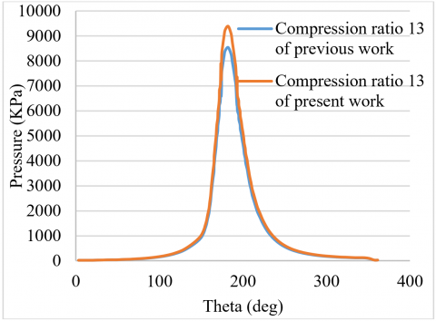
The model and predict of previous work [23] where the performance characteristics and emitted pollutants of a GDI engine based on analyzing the crucial parameters like engine speed ranging from 2000 to 6000 rpm, compression ratio ranging from 9 to 13 and start of ignition ranging from 140 to 180 deg. The combustion processes occurring in a four-cylinder, four-stroke direct injection gasoline engine where the two zones combustion process take place were modeled using MATLAB at specific parameters. It indicates that GDI engine parameter changes have a significant impact on its performance and emissions. Low engine speed has produced peak in cylinder pressure, burnt and unburned temperature, total power output, CO & NOx emissions. While increment in heat transfer rate has been observed as the engine speed rises and there is also evidence that the power per cycle at the speed of 2000 rpm, fuel injection pressure 40 MPa, and start of ignition 165 degree of crankshaft. As the amount of cylinder pressure raised by increasing the compression ratio between 9 and 13, group B observed there is almost no impact of a compression ratio on temperature both in the burned and unburned zone [23]. The comparison process was made with this previous research [23], using the ANSYS program and the obtaining results show that there was close to 8% error as shown in Figure 14.
Figure 14. In-cylinder pressure for different angle between present work and previous work [23]
4.6 Comparison with existing literature
The findings of this study align with and expand upon the existing body of research on injector configuration effects in internal combustion engines. Several key comparisons highlight the contributions of this work to the broader field:
1. Injector angle and combustion dynamics
Previous studies, such as those by Pham et al. [5] and Hamdi et al. [6], have demonstrated that injector angle significantly influences combustion efficiency and emissions in internal combustion engines. Pham et al. reported that narrower spray angles enhance fuel-air mixing, resulting in more efficient combustion but also increased NOx emissions due to higher combustion temperatures. Our study corroborates these findings, showing a consistent trend where narrower angles (40°) result in higher peak pressures and temperatures, confirming the relationship between injector angle, mixing efficiency, and thermal NOx formation.
However, this study advances the understanding by providing a more detailed analysis of how varying angles (from 40° to 70°) systematically affect both combustion efficiency and emissions across a broader range of configurations. This broad strategy proves useful in defining the best angles that provide the best balance between power and pollution, something that previous studies with relatively narrow angles failed to capture.
2. Injector diameter and atomization quality
Yousif and Mashkour [21] have explained the details regarding the relation between the injector diameter and atomization quality as well as combustion efficiency in the previous work. They commented that greater sizes of injectors’ openings might impair atomization, thus contributing to reduced combustion efficiency and increased emissions of HC and NOx. These observations are supported by our results, which reveal that with an increase in the orifice diameter to 6mm there is a consequent increase in both the peak pressure and temperature but a penalty of higher NOx emissions due to poor atomization of fuel.
This study adds a measure of depth by calculating changes in pressure, temperature, and emissions because of differences in injector diameters in a single paper. It allows for a better understanding of the consequences of increasing injector diameters, which can be seen as an advantage, given that the previous works could have compared a limited number of diameter differences.
3. Emissions control and efficiency trade-offs
The effects of compromising between the two objectives of engine optimization and low emission have been illustrated in the literature. Research works done by Nemati et al. [16] provide insight into the problems of low emission and high efficiency of the engine. This is a direction of our findings, in addition to the discussions of various configurations which may maximize performance such as 40° injector angle and 6 mm diameter, these produce more NOx emissions, therefore, the demand for enhanced emission control systems.
Thus, the contribution of this work can be seen in the accurate investigation of these trade-offs for a number of injector configurations, which can be employed to design engines that are balanced in terms of performance and emissions. Thus, by changing injector angle and diameter systematically, this paper provides a more extensive set of data that will be useful in future design and improvement of internal combustion engine technologies.
A numerical study of internal combustion engines with two mixture inlets and two exhaust outlets using diesel. The simulation process is carried out using the Ansys IC Engine program by changing the spray angle and the diameter of the injector and obtaining temperature and pressure diagram at a rotation speed of 1800 revolutions per minute. The concluding points are as follow:
1. The pressure rise of internal combustion engines improves with the reduction in injector angle increase in combustion temperature. The pressure value is 10.65 MP at 40 degrees, 10.12 MPa, at 50 degrees, 9.31 up to 31 MPa at 60 degrees and is 8.45 MPa at 70 degrees.
2. A diagram illustrates this relationship as the temperature rises when the injector angle reduces, therefore, raising the combustion value. The temperature point measured is 1309 K at 40 degrees, 1243 K at 50 degrees, 1039 K at 60 degrees and 945 K at 70 degrees.
3. The velocity particle tacking change in internal combustion engines rises with the reduction of injector angle and therefore rises the injector speed and combustion temperature. The velocity particle tacking value rises to 9.66 m/s at 40 degrees, 9.02 m/s at 50 degrees, 8.15 m/s at 60 degrees, and 7.89 m/s at 70 degrees.
4. The pressure value rises with the diameter of the injector because when the diameter of the injector is large, a large amount of the mixture enters the combustion chamber and a large explosion takes place and thus the temperature rises and the pressure values reach 8.45 MPa, 8.87 MPa, and 9.29 MPa.
5. The size of the injector particularly the diameter has a profound effect on the temperature distribution in an internal combustion engine. Smaller diameters provide better combustion and lower emission levels, whereas larger diameters result in poor atomization, non-uniform temperature distribution and higher emission levels. It is evident that simulations play a critical role in determining the optimal injector diameter for combustion, heat rejection, and minimal emissions. The pressure and temperature rise as the diameter does, and this leads to a higher temperature value.
6. The injector diameter has a direct effect on the velocity particle tacking value as it increases the amount of mixture that enters the combustion chamber thus causing a larger explosion and therefore leading to a higher velocity particle tacking. The larger diameter results in higher pressure, where a velocity particle tacking value is 7.86 m/s with a 2 mm injector, 8.15 m/s with a 4 mm injector, and 9 m/s for 6 mm.
7. The mass value of No gas increases with injection angle, reaching 1.051 e-18 at 40 degrees, 1.156 e-18 at 50 degrees, and 1.261 e-18 at 70 degrees. The contamination value increases with injector diameter, reaching 1.032 e-22 at 2 mm and 9.46 e-23 at 6 mm, indicating that increasing the diameter of the injector increases fuel supply and exhaust gas emissions.
Taking into account the findings of the literature review alongside the simulation results, one can identify a number of research directions for discussion in the context of numerical analysis of injector angles for internal combustion engines. Firstly, we should continue to investigate the effects of various injector angles and injection positions on temperature and pressure fields in the combustion chamber. As this research avenue shows, combustion enhancement and emissions control are potential areas of improvement that can benefit from future investigations. Secondly, investigating the effects of different spray angles and injectors positions in amount of fuel droplets and air to fuel ratio is essential to climb engine performance.
Furthermore, future studies should aim at combining enhanced CFD techniques with experimental validation to explain the reliability of the numerical models used in such studies. This may help in improving the ability of simulation tools to predict the efficiency of better internal combustion engines, in order to be developed. Further, one may also adapt the analysis of the impacts of pilot fuel injection timing on combustion characteristics under various operational conditions to enhance the understanding of combustion phenomena in dual-fuel engines.
Additionally, research in other future fuel injection techniques such as hydrogen direct injection (HDI) for internal combustion engines may be a path to zero-carbon combustion technologies. Understanding the challenges associated with the design and fabrication of hydrogen injectors and addressing issues concerning poor lubricity and permeability of hydrogen can help in developing more efficient renewable energy systems in transportation sub-sector. This study provides a comprehensive analysis of the effects of injector angle and diameter on internal combustion engine performance and emissions, using detailed CFD simulations. The findings include:
• Impact of Injector Angle: A research study carried out on the effects of injector angles revealed that, using a narrow injector angle such as forty degrees raised the peak cylinder pressure and combustion temperature thus increasing the combustion efficiency but at the same time increasing the NOx emissions. This implies that though narrow angles could increase engine performance, there might be the need to add other measures to meet the emission standards.
• Impact of Injector Diameter: Bigger injector bores (for instance, 6 mm) enable more fuel delivery and, as a result, the print elevated pressure and temperature in the combustion chamber. But they also negatively affect atomization to a lower extent in addition to raising emissions of unburned HC and NOx. This means that there is a compromise between attaining the greatest power output and the least emissions.
• Emissions Trade-offs: It also demonstrates the conflict that is always present between achieving the best results for an engine and preventing it from polluting the environment. It is important to note that configurations that tend to achieve higher performance levels also lead to higher NOx emissions; hence, the need to incorporate technologies such as EGR or SCR.
This paper proposes the following areas for future research in a bid to enhance internal combustion engines. It recommends seeking other sources of fuel, comparing engines and their layouts and sizes, and verifying the calculations of CFD simulations. It also provides critical information regarding considering technologies of injectors like variable geometry injectors or even the dual stage injection systems of various kinds for better control of the injection parameters. There is a possibility of working with real-time optimization algorithms to control injection parameters according to the load and other factors. It also recommends that one should investigate the impact of the environment on the engine like the temperature and the altitude so that engines that will work well in different conditions are developed. Last but not the least, determining the long term wear and tear and the associated maintenance needs of engines equipped with different injector designs might be helpful for both, the manufacturers and the users.
[1] Dai, X., Zheng, Z. (2021). Effects of piston shape on the performance of a gasoline direct injection engine. ACS Omega, 6(50): 34635-34649. https://doi.org/10.1021/acsomega.1c05037
[2] Balijepalli, R., Kumar, A., Rajak, U., Elkotb, M.A., Alwetaishi, M., Dasore, A., Verma, T.N., Saleel, C.A., Afzal, A. (2021). Numerical investigation of the effect of spray angle on emission characteristics of a diesel engine fueled with natural gas and diesel. Energy Reports, 7: 7273-7287. https://doi.org/10.1016/j.egyr.2021.10.089
[3] Sonachalam, M., Manieniyan, V. (2021). Optimization of critical angle, distance and flow rate of secondary fuel injection in DI diesel engine using computational fluid dynamics. SN Applied Sciences, 3: 1-13. https://doi.org/10.1007/s42452-020-04138-3
[4] Bhosale, A., Patil, S., Dhepe, V., Banosde, K., Kakde, R., Teltumade, R., Lengare, D. (2022). 3-D numerical study of effect of urea injector location and intake cone geometry on SCR performance. International Journal of Innovative Research and Scientific Studies, 5(2): 47-58. https://doi.org/10.53894/ijirss.v5i2.378
[5] Pham, V.C., Le, V.V., Yeo, S., Choi, J.H., Lee, W.J. (2022). Effects of the injector spray angle on combustion and emissions of a 4-stroke natural gas-diesel DF marine engine. Applied Sciences, 12(23): 11886. https://doi.org/10.3390/app122311886
[6] Hamdi, F., Agrebi, S., Idrissi, M. S., Mondo, K., Labiadh, Z., Sadiki, A., Chrigui, M. (2022). Impact of spray cone angle on the performances of methane/diesel RCCI engine combustion under low load operating conditions. Entropy, 24(5): 650. https://doi.org/10.3390/e24050650
[7] Shateri, A., Jalili, B., Saffar, S., Jalili, P., Ganji, D.D. (2024). Numerical study of the effect of ultrasound waves on the turbulent flow with chemical reaction. Energy, 289: 129707. https://doi.org/10.1016/j.energy.2023.129707
[8] Chang, Y., Zou, J. (2023). Experimental and numerical study on the ablation analysis of a pintle injector for GOX/GCH4 rocket engines. Coatings, 13(6): 1022. https://doi.org/10.3390/coatings13061022
[9] Chen, T.Y., Yang, C.C., Ouyang, K. (2024). An experimental and numerical study on the cavitation and spray characteristics of micro-orifice injectors under low-pressure conditions. Energies, 17(5): 1045. https://doi.org/10.3390/en17051045
[10] Taghavifar, H., Shervani-Tabar, M.T., Abbasalizadeh, M. (2015). Numerical study of the effects of injector needle movement and the nozzle inclination angle on the internal fluid flow and spray structure of a group-hole nozzle layout. Applied Mathematical Modelling, 39(23-24): 7718-7733. https://doi.org/10.1016/j.apm.2015.04.032
[11] Pham, V.C., Choi, J.H., Rho, B.S., Kim, J.S., Park, K., Park, S.K., Le, V.V., Lee, W.J. (2021). A numerical study on the combustion process and emission characteristics of a natural gas-diesel dual-fuel marine engine at full load. Energies, 14(5): 1342. https://doi.org/10.3390/en14051342
[12] Jamil, A., Baharom, M.B., Aziz, A.R.A. (2021). IC engine in-cylinder cold-flow analysis–A critical review. Alexandria Engineering Journal, 60(3): 2921-2945. https://doi.org/10.1016/j.aej.2021.01.040
[13] Zhang, Z., Dai, X., Zheng, Z. (2022). Numerical simulation study on the effect of port water injector position on the gasoline direct injection engine. Processes, 10(10): 1909. https://doi.org/10.3390/pr10101909
[14] Yip, H.L., Srna, A., Yuen, A.C.Y., Kook, S., Taylor, R. A., Yeoh, G.H., Medwell, P.R., Chan, Q.N. (2019). A review of hydrogen direct injection for internal combustion engines: Towards carbon-free combustion. Applied Sciences, 9(22): 4842. https://doi.org/10.3390/app9224842
[15] Mahmood, H.A., Adam, N.M., Sahari, B.B., Masuri, S.U. (2017). New design of a CNG-H2-air mixer for internal combustion engines: An experimental and numerical study. Energies, 10(9): 1373. https://doi.org/10.3390/en10091373
[16] Nemati, A., Ong, J.C., Pang, K.M., Mayer, S., Walther, J.H. (2022). A numerical study of the influence of pilot fuel injection timing on combustion and emission formation under two-stroke dual-fuel marine engine-like conditions. Fuel, 312: 122651. https://doi.org/10.1016/j.fuel.2021.122651
[17] Abdollahi, S.A., Jafari, M., Aminian, S., Fattahi, M., Uyen, P.D. (2023). Fuel mixing enhancement of transverse coaxial air and fuel jet by upstream shock wave on in scramjet engines: Numerical study. Scientific Reports, 13(1): 18501. https://doi.org/10.1038/s41598-023-45810-z
[18] Choubey, G., Pandey, K.M. (2017). Numerical studies on the performance of scramjet combustor with alternating wedge-shaped strut injector. International Journal of Turbo & Jet-Engines, 34(1): 11-22. https://doi.org/10.1515/tjj-2015-0048
[19] Fan, L., Shi, Q., Lin, W., Tong, Y., Sun, J., Nie, W. (2022). Numerical simulation of similarities between rotating detonation and high-frequency combustion instability under two mixing schemes. AIP Advances, 12(2): 025310. https://doi.org/10.1063/5.0079455
[20] Kim, J.S., Lee, W.J., Pham, V.C., Choi, J.H. (2022). A numerical study on fuel injection optimization for a ME-GI dual-fuel marine engine based on CFD analysis. Applied Sciences, 12(7): 3614. https://doi.org/10.3390/app12073614
[21] Yousef, O., Mashkour, M. (2024). Effects of nozzle diameter and holes number on the performance and emissions of a gasoline direct injection engine. International Journal of Thermodynamics, 27(1): 1-12. https://doi.org/10.5541/ijot.1272871
[22] Yousif, O., Mashkour, M. (2023). Mathematical modeling and evaluation of fuel injection pressure effects on the performance and emissions of gasoline direct injection engine. Journal of Engineering Science and Technology, 255-274.
[23] Yousif, O., Mashkour, M. (2023). Engineering and technology journal, parametric analysis for performance and emissions of gasoline direct injection engine by using the mathematical modeling. https://magazine.sciencepod.net/parametric-analysis-for-performance-and-emissions-of-gasoline-direct-injection-engine-using-mathematical-modelling/.