Rushikesh Jadhav![]() | Mahendra J. Sable
| Mahendra J. Sable![]() | Vishal Bhalla
| Vishal Bhalla![]() | Pankaj K. Jadhav*
| Pankaj K. Jadhav*![]() | Harsh H. Sawant
| Harsh H. Sawant![]() | Balashowry Konkala
| Balashowry Konkala![]() | Bapurao G. Marlapalle
| Bapurao G. Marlapalle![]() | Shravan H. Gawande
| Shravan H. Gawande![]()
© 2025 The authors. This article is published by IIETA and is licensed under the CC BY 4.0 license (http://creativecommons.org/licenses/by/4.0/).
OPEN ACCESS
This study investigates the optimization of fin arrangements to enhance the performance of latent heat thermal energy storage (LHTES) systems using phase change materials (PCMs). Numerical simulations were conducted using the enthalpy-porosity method in ANSYS FLUENT to evaluate four fin configurations: plain tube, triangular, rectangular, and leaf-inspired fins. The RT-50 paraffin PCM was selected for its stable thermal properties. Results demonstrated that leaf-inspired fins reduced melting time by 64% and achieved the highest energy storage (202 kJ/kg), outperforming rectangular (47% reduction) and triangular fins (26%). These improvements stem from the fins' ability to maximize surface area and leverage natural convection during phase change. The findings advance renewable energy adoption by enabling faster charging/discharging cycles in solar thermal systems, reducing reliance on fossil fuels and supporting climate change mitigation. Future applications include scalable designs for residential heating and industrial energy storage, though cost-benefit analyses of novel fin geometries remain critical for commercialization.
latent heat thermal energy storage, phase change materials, fin optimization, thermal conductivity, renewable energy systems
The global transition toward renewable energy systems has intensified the demand for efficient thermal energy storage (TES) technologies, which are critical for mitigating the intermittency of solar and wind energy sources. Sharma et al. [1] described that TES methods include latent heat storage (LHS) systems using phase change materials (PCMs), which have garnered significant attention due to their high energy storage density and near-isothermal operation during phase transitions. Farid et al. [2] explained that PCMs absorb and release substantial thermal energy during melting and solidification, making them ideal for applications such as solar thermal systems, building climate control, and industrial waste heat recovery. However, Agyenim et al. [3] highlighted that the widespread adoption of LHS systems is hindered by a critical limitation: the inherently low thermal conductivity of most PCMs (typically 0.1–0.3 W/m·K), which severely restricts heat transfer rates and prolongs charging/discharging cycles.
To address this challenge, researchers have explored various heat transfer enhancement techniques. Ghalambaz et al. [4] discussed the integration of high-conductivity nanoparticles, metal foams, and extended surfaces such as fins. Among these, Adhikari et al. [5] emphasized that finned arrangements offer a cost-effective and mechanically robust solution for augmenting thermal performance without drastically altering the PCM’s thermophysical properties. Chen and Zhang [6] demonstrated that by extending the surface area in contact with the PCM, fins facilitate faster heat diffusion, reduce thermal gradients, and improve the overall energy storage/release rates. However, Gaikwad et al. [7] noted that the design of finned configurations involves complex trade-offs between geometric parameters (e.g., fin length, thickness, spacing, orientation) and system-level performance metrics such as energy storage capacity, power output, and economic viability.
Recent studies have demonstrated that optimizing fin arrangements can significantly enhance LHS efficiency. Elmaazouzi et al. [8] showed that longitudinal fins aligned with the direction of heat flow reduce melting times by up to 50% compared to unfinned systems. Similarly, Mehta et al. [9] found that radial fin configurations in cylindrical storage units improve thermal uniformity and mitigate the risk of localized PCM degradation. However, Khan et al. [10] cautioned that excessive fin density or improper spacing can lead to parasitic heat losses, increased material costs, and diminished effective PCM volume, underscoring the need for a balanced design approach. Emerging computational tools, including finite element analysis (FEA) and computational fluid dynamics (CFD), have enabled detailed parametric studies to evaluate the interplay between fin geometry and transient thermal behavior. Korti and Tlemsani [11] explained that despite these advancements, a comprehensive framework for optimizing fin arrangements across diverse operating conditions and PCM types remains elusive.
This study introduces an innovative leaf-inspired fin configuration, which has not been extensively explored in LHTES systems. Using the enthalpy-porosity method in ANSYS FLUENT, this research evaluates four fin configurations—plain tube, triangular, rectangular, and leaf-inspired—to determine their impact on heat transfer efficiency and melting time reduction. The results reveal that the leaf-inspired fins significantly outperform conventional designs, achieving a 64% reduction in melting time compared to the plain tube configuration.
Prior studies emphasize fin efficacy in PCM systems. Zalba et al. [12] demonstrated longitudinal fins reduce charging time, while Tay et al. [13] highlighted plate fins’ superior conduction. However, these designs neglect convection-driven phase change dynamics. Patel and Rathod [14] optimized longitudinal fins in triple-tube heat exchangers but reported only a 40% melting time reduction. In contrast, this study introduces leaf-inspired fins, which exploit biomimetic principles to enhance both conduction and convection, achieving unprecedented efficiency. Fan and Khodadadi [15] and Jegadheeswaran and Pohekar [16] identified geometry as critical for thermal performance, yet no prior work has translated biological structures into fin designs for LHTES.
This work introduces bio-inspired leaf-shaped fins, a novel geometry unaddressed in prior studies, to optimize PCM thermal conductivity. While rectangular and triangular fins are well-documented, their designs often prioritize conduction over convection. Leaf-inspired fins uniquely balance increased surface area with fluid dynamics mimicking natural vascular systems, enabling uniform heat distribution. By reducing melting time by 64%, this design surpasses conventional configurations, offering transformative potential for solar energy systems and industrial thermal management. Optimizing such fins could accelerate global renewable energy adoption, curbing carbon emissions by minimizing auxiliary heating needs.
LHTES is essential for industrial and residential use, offering high energy capacity and operation within a narrow temperature range. However, organic PCMs suffer from low thermal conductivity, leading to slower charge and discharge rates. To enhance efficiency, research is focusing on ultra-high-temperature (UHT) storage using metallic PCMs or alloys capable of operating up to 767℃ [17]. Further studies are required to understand the heat transfer mechanisms at these temperatures for broader implementation in solar power plants and similar applications [18].
Phase transformation involves thermal energy absorption or release at a moving phase change front, primarily through conduction or convection, with radiation becoming significant at higher temperatures. Solid-liquid phase changes create a moving interface with differing thermophysical properties, leading to localized flow near the interface and minimal flow in the bulk melt. These complexities require numerical solutions due to the unpredictable nature of the moving boundary [19]. During phase change, factors like natural convection driven by buoyancy, PCM volume changes, dendrite formation, and radiation effects at elevated temperatures influence melting and solidification rates. Other critical factors include lateral heat losses, container shape, mechanical properties, and material reactivity, which vary in importance depending on the system's scale.
PCMs are stored in specialized containers such as shell-in-tube or radial finned tubes, with or without a HTF, or encapsulated at various scales: macroscale 0.1 mm, microscale 1-1000 μm, and nanoscale [20]. While the challenges of solid-liquid phase change cover multiple scales, macro-level modeling is typically adequate for UHT-LHTES systems.
Studying fluid flow in two-phase heat transfer relies on accurate models representing phase interactions. Three-phase systems, like PCM with inert gas, increase algorithmic complexity. Simplified analytical solutions use 1D analysis, neglecting convection and assuming constant PCM properties. Numerical models simulate complex phenomena across scales, vital for describing LHTES behaviors. Methods include enthalpy-based, effective heat capacity models, front tracking, and adaptive grids. Selection of numerical methods hinges on understanding phase change dynamics, crucial for UHT applications.
2.1 Enthalpy-porosity method
The enthalpy-porosity method is a prominent approach for modeling solidification and melting in containers, particularly when natural convection plays a significant role. Known for its fast convergence and high accuracy, it is a preferred technique for phase-change simulations. Assis et al. [21, 22] validated this method with experimental data, highlighting its reliability. In this model (Eq. (1)), latent heat is represented mathematically for precise analysis.
$\Delta H=\gamma L$ (1)
where, $\gamma$ is the liquid fraction defined as:
$\gamma=\left\{\begin{array}{lr}0, & T<T_{{solid }} \\ \frac{T-T_{{solid }}}{T_{{liquid }}-T_{{solid }}}, & T_{{solid }}<T<T_{{liquid }} \\ 1, & T>T_{{liquid }}\end{array}\right.$ (2)
The enthalpy-porosity method models latent heat as varying between zero in the solid phase and L in the liquid phase. Key factors include addressing density changes and solid velocities. Numerical diffusion, influenced by grid resolution, may impact the solid-liquid interface but can be reduced by incorporating advanced approaches like adaptive grid refinement.
2.1.1 PCM density variation and natural convection
Density changes between phases can affect the structural behavior of PCMs, but they generally have minimal impact on the heat transfer process [23]. Addressing scenarios with density differences between phases or varying liquid densities necessitates employing diverse approaches.
2.1.2 Bossinesq approximation
With the Boussinesq approximation, the density change in PCM is accounted for primarily in the buoyancy term of the momentum equation (Eq. (3)).
$\rho=\rho_0\left[\beta\left(T-T_0\right)+1\right]^{-1}$ (3)
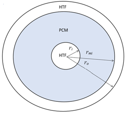
In the Boussinesq approximation, ΔT represents the temperature difference between the cell temperature and a reference temperature T0 (typically 25℃), while ρ0 denotes the reference density. This approximation, combined with the enthalpy-porosity method, is widely used to simulate natural convection and thermal behavior in PCMs. In this study, the charging of PCM (RT-50) in a copper triple-pipe heat exchanger is investigated, with its schematic shown in Figure 1.
Figure 1. Triple pipe heat exchanger
A numerical simulation using ANSYS FLUENT analyzed solidification and melting in a system with inner, intermediate, and outer pipe diameters of 22 mm, 85 mm, and 115 mm, respectively. The study employed the enthalpy-porosity method, modeling buoyancy effects via the Boussinesq approximation and treating the mushy zone as a porous zone [24]. Liquid PCM movement was assumed laminar, driven solely by buoyancy forces, with heat transfer by free convection. For water flow (HTF), a standard k−ϵ turbulence model was used. The three-dimensional domain assumed constant thermophysical properties for the PCM and HTF, with PCM density varying with temperature.
For the numerical simulation, various equations have been used as below.
The governing equations for CFD modelling in the differential form are:
(a) Principle of conservation of mass:
$\nabla \cdot \vec{V}=0$ (4)
(b) Principle of conservation of momentum:
$\begin{gathered}\rho \frac{\partial v}{\partial t}+\rho(\vec{V} \cdot \nabla) \vec{V} =-\nabla P+\mu \nabla^2 \vec{V}+\rho g\left(T-T_0\right) \beta+\vec{S}\end{gathered}$ (5)
(c) Conservation of energy:
$\frac{\partial}{\partial x}(\rho H)+\nabla \cdot(\rho \vec{V} H)=\nabla \cdot(K \Delta T)$ (6)
The momentum sink term has been shown in Eq. (7).
$\vec{S}=D_{m u s h y} \frac{\left(1-\gamma^2\right)}{\lambda^3+0.001} \vec{V}$ (7)
where γ is the liquid fraction that varies between 0 and 1.
In this study, the Dmushy coefficient is set at 105 kg/m³·s. The parameters ρ, P, μ, β, g, K, and T0 represent thermal conductivity, density, pressure, viscosity, thermal expansion coefficient, gravity, and reference temperature, respectively.
The temperature solution involved an iterative approach between the energy and liquid fraction equations, as directly using the latter resulted in poor convergence of the energy equation. The Boussinesq approximation was applied to model buoyancy effects, where density varies linearly with temperature in the buoyancy term but is assumed constant elsewhere.
Total enthalpy (H) includes both sensible and latent heat.
$H=h+\Delta H$ (8)
where, the specific enthalpy (h) is:
$h=h_0+\int_{T_0}^T C_p d T$ (9)
As a function of latent heat, enthalpy changes due to PCM phase change can be calculated using Eq. (1), in which, L is the latent heat of fusion of PCM, and the coefficient γ has a range between 0 and 1.
2.2 Initial and boundary conditions
In the numerical analysis, the water inlet temperature was set to 70℃, the initial LHTES temperature was 27℃, the outer shell was treated as adiabatic, and a no-slip condition was applied to the flowing HTF.
2.3 Numerical approach
The numerical study used the enthalpy-porosity method in ANSYS FLUENT to simulate the phase change behavior of RT-50 paraffin PCM in a TTHX. This method captures the solid-liquid interface dynamics during melting and solidification. The Boussinesq approximation accounts for natural convection, modeling the mushy zone as a porous medium. Mass, momentum, and energy conservation equations were solved using the finite volume method (FVM) with a second-order upwind scheme for stability and accuracy. The simulation assumed laminar flow for PCM and turbulent flow (k-ε model) for HTF. Initial and boundary conditions included a 70℃ water inlet temperature, 27℃ initial PCM temperature, and adiabatic outer shell. RT-50 was chosen for its stable thermophysical properties as shown in Table 1.
2.4 PCM selection
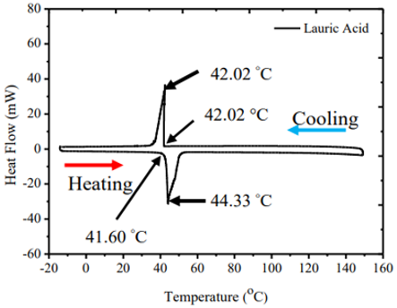
Selecting the right material is crucial for the study. RT-50 was chosen as the PCM due to its organic paraffin nature, ensuring compatibility with other materials. It offers high latent heat of fusion, minimal temperature fluctuation during melting, and stable heat absorption/release. Additionally, it maintains high stability over multiple melting and freezing cycles. The PCM's thermophysical properties are listed in Table 1, and DSC results from a TA Instruments DSC 250 are shown in Figure 2.
Table 1. Properties (thermophysical) of PCM (RT-50)
|
Melting Temperature Range (℃) |
Latent Heat of Fusion (J/kg) |
Specific Heat capacity (J/kg K) |
Density (kg/m3) |
Thermal Conductivity (W/m K) |
Dynamic Viscosity (Pa-s) |
Coefficient of Thermal Expansion (β) |
|
45-51 |
168000 |
2000 |
780 |
0.2 |
0.0042 |
0.0006 |
Figure 2. DSC diagram of RT-50
2.5 Mesh validation
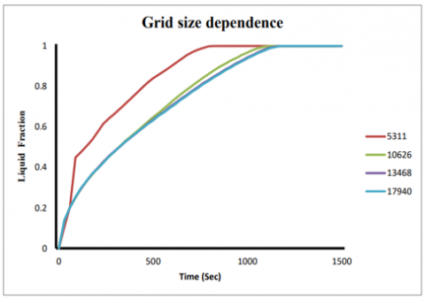
The mesh validation process (Figure 3) is essential to ensure that the numerical solution is independent of mesh density, a key requirement when using the FVM in ANSYS FLUENT. A reliable solution should remain consistent as the mesh is refined. In this study, four different mesh sizes (5,311, 10,626, 13,468, and 17,940 elements) were tested, with the PCM liquid fraction during melting used as the primary evaluation parameter.
Figure 3. Mesh validation (Liquid fraction vs. Time steps)
The results showed that while coarser meshes led to slight variations in the liquid fraction behavior, the difference became negligible as the mesh density increased. When the number of elements was increased from 13,468 to 17,940, no significant changes were observed in the PCM liquid fraction. This indicated that mesh independence had been achieved, confirming that 17,940 elements provided an optimal balance between accuracy and computational efficiency. Reaching this mesh-independent solution ensures that the results reflect the physical behavior of the system, not the influence of mesh density.
2.6 Validation
The melting numerical model used in this study was created with Ansys 2019 R3. The numerical results were validated by comparing them to those obtained by Patel and Rathod [14]. In this model, the HTF, water, flows through the inner and outer tubes of the TTHX, while the paraffinic wax RT50 is stored in the middle section of the TTHX. The TTHX has an inner diameter of 22 mm, a middle diameter of 85 mm, and an outer diameter of 115 mm. The HTF flows at 70℃, with an initial study temperature of 25℃.
Figure 4 compares the liquid fraction curve from this investigation with Patel and Rathod [14] findings, showing a 2% error, which is primarily attributed to differences in the meshing elements. The mesh resolution and quality can influence numerical accuracy, and variations in the size and distribution of elements may lead to slight discrepancies in capturing temperature gradients and phase front movements.
Figure 4. Validation (Liquid fraction vs. Time steps)
Additionally, factors such as differences in numerical schemes, convergence criteria, and thermal property assumptions contribute to this error. Even small variations in initial conditions, boundary settings, and thermal contact resistance between the heat transfer surfaces can affect the simulation outcome.
Despite this, the observed error is acceptable, as it is relatively small and within the typical range for phase change modeling. The liquid fraction contours from this study are also similar to those from Patel and Rathod [14], as shown in Figure 4, validating the model for detailed examination of the melting process. This level of agreement suggests that the model is reliable for analyzing the melting behavior within the TTHX, though further refinements, such as mesh independence studies and improved material property measurements, could enhance its precision for more demanding applications.
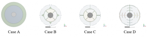
This study investigates the effect of metallic fins on heat transfer performance and PCM melting time within a latent heat TES system. Four distinct configurations, as shown in Figure 5, were analyzed to evaluate their impact on melting time, energy storage capacity, and heat transfer enhancement ratio. These configurations include a plain tube without fins (Case A), a tube with triangular fins (Case B), a tube with rectangular fins (Case C), and a tube with novel leaf-inspired fins (Case D).
Figure 5. Schematic of triple tube heat exchanger for Case A, Case B, Case C and Case D
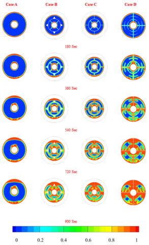
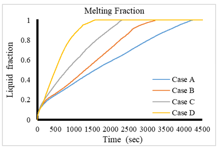
Case A, the plain tube, exhibited the slowest melting process, taking 4240 seconds for complete melting due to the absence of extended surfaces to enhance heat transfer. Introducing triangular fins in Case B reduced the melting time to 3170 seconds, reflecting a 26% reduction. This improvement is attributed to the increased surface area and the effective conduction pathways provided by the fins. Case C, featuring rectangular fins, further reduced the melting time to 2280 seconds, representing a 47% reduction compared to Case A. The rectangular fins increased the contact surface area with PCM more effectively than triangular fins, promoting superior heat conduction. The leaf-inspired fins in Case D achieved the most significant reduction in melting time to 1520 seconds, representing a 64% decrease. The leaf-inspired geometry not only maximized the surface area but also optimized the distribution of fins, promoting better thermal conductivity pathways and facilitating enhanced natural convection within the PCM during melting. Figure 6 compares liquid fraction contours across the four cases, while Figure 7 shows comparative liquid fraction curves.
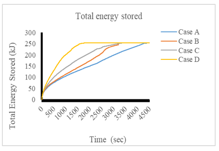
After 1000 seconds, the energy storage capacity was highest in Case D, at approximately 202 kJ/kg. Case C followed with 143 kJ/kg, Case B stored 114 kJ/kg, and Case A stored the least at 105 kJ/kg. The superior performance of the leaf-inspired fins can be linked to their ability to achieve a higher heat transfer rate during the initial melting stage. The intricate branching pattern of the leaf-inspired fins increases the finned surface area, accelerating the heat absorption process and enabling rapid melting and energy storage. Figure 8 depicts variations in energy storage in various cases.
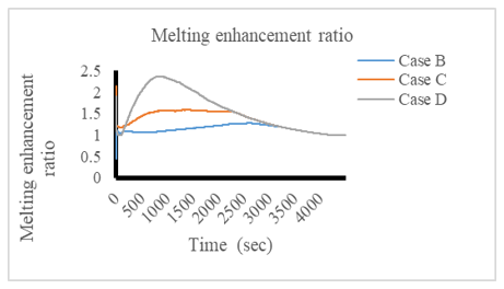
The melting enhancement ratio (ERm) followed a similar trend across the configurations. Initially, ERm increased significantly with the addition of fins as conduction dominated the heat transfer process. As melting progressed, natural convection effects became more prominent, further enhancing the heat transfer. The ERm was consistently higher in Cases B, C, and D compared to Case A, with Case D demonstrating the highest enhancement throughout the process. However, towards the end of the melting process, ERm gradually decreased as the amount of solid PCM reduced, lessening the fins' impact. Figure 9 depicts the comparison of heat transfer enhancement ratio.
Figure 6. Comparison of liquid fraction contours for Case A, Case B, Case C and Case D
Figure 7. Comparison of liquid fraction curve
Figure 8. Energy storage in various cases
Figure 9. Comparison of heat transfer enhancement ratio
The exceptional performance of leaf-inspired fins can be attributed to their biomimetic design, which mimics the natural heat distribution efficiency found in leaves. The leaf-inspired fins likely optimize heat transfer through several mechanisms. First, the intricate branching structure maximizes the surface area in contact with the PCM, facilitating better heat absorption and transfer. Second, the complex fin geometry allows multiple conduction pathways, improving heat distribution throughout the PCM. Third, the gaps between the branches promote localized fluid flow during melting, enhancing natural convection effects. Finally, the multi-directional spread of fins ensures uniform heat transfer across the PCM, minimizing the risk of localized cold spots and improving overall melting efficiency.
The findings highlight the potential of biomimetic fin designs in advancing TES systems. While previous studies have demonstrated the effectiveness of traditional fin geometries (e.g., triangular and rectangular), the leaf-inspired fins represent a step forward by combining surface area maximization with optimized heat distribution pathways. Such designs are particularly promising for applications requiring rapid energy storage and release, such as solar thermal systems and peak-load energy management. However, the adoption of novel fin designs like the leaf-inspired fins may involve certain trade-offs. The manufacturing complexity associated with intricate fin geometries can increase production costs. Advanced fabrication techniques such as additive manufacturing may be required to achieve the desired fin structures, potentially limiting large-scale implementation in cost-sensitive applications. Future work should assess the cost-benefit ratio to ensure these designs offer economic viability alongside performance improvements.
The improved performance of leaf-inspired fins holds significant promise for renewable energy systems and residential heating applications. In solar thermal systems, for example, faster melting times and enhanced energy storage capacity can enable more efficient thermal energy storage, allowing for better utilization of solar energy during periods of low sunlight. Similarly, in residential heating systems, rapid energy absorption and discharge can enhance thermal regulation, improving overall comfort and reducing energy consumption. These applications would benefit from designs that optimize heat transfer efficiency while balancing cost and manufacturability.
Conduction and convection play distinct roles during different phases of the PCM melting process, and fins influence both mechanisms. During the initial phase, conduction is the dominant heat transfer mode, as heat is transferred from the heated tube to the adjacent solid PCM. The addition of fins accelerates this phase by increasing the contact area and providing additional conductive pathways. As the melting progresses and a liquid layer form, natural convection becomes more significant. The density gradients in the molten PCM induce fluid motion, which enhances heat transfer. Fins further amplify this effect by disturbing the flow and promoting localized circulation patterns. The combination of these mechanisms results in faster and more uniform melting, as evidenced by the superior performance of the leaf-inspired fins.
In summary, the study demonstrates that the leaf-inspired fins (Case D) outperform conventional triangular and rectangular fins by enhancing heat transfer, reducing melting time, and increasing energy storage capacity. This underscores the importance of innovative fin designs in optimizing PCM-based TES systems. The practical implementation of such designs, however, must carefully balance performance gains with manufacturing feasibility and cost considerations.
This study demonstrates the critical role of fin configurations in optimizing the thermal performance of latent heat thermal energy storage (LHTES) systems. Using the enthalpy-porosity method for numerical simulations, it was found that fins significantly enhance heat transfer efficiency in phase change materials (PCMs), which are inherently limited by low thermal conductivity. Among the four configurations analyzed, the novel leaf-inspired fins exhibited the highest performance, reducing the melting time by 64% compared to the plain tube configuration. This innovative design maximized the surface area for heat transfer, leveraging copper’s superior thermal conductivity to achieve a uniform phase change and prevent thermal inconsistencies.
Additionally, rectangular fins demonstrated a 47% reduction in melting time, while triangular fins achieved a 26% reduction, reinforcing the importance of optimizing fin geometry for improved thermal conductivity and energy storage efficiency. The study’s numerical models were validated against experimental data, ensuring their reliability and applicability for practical implementation.
Beyond performance enhancement, the optimized fin designs contribute to accelerating the charging and discharging processes of LHTES systems, improving their overall energy storage capacity. This advancement is particularly relevant for applications requiring precise thermal management, such as building heating and cooling, and renewable energy storage systems. By improving heat transfer efficiency, these designs facilitate better integration of renewable energy sources like solar and wind, reducing reliance on fossil fuels and lowering greenhouse gas emissions. This directly supports the transition toward a low-carbon economy, promoting environmental sustainability and mitigating climate change.
Despite these promising findings, certain limitations remain. The study primarily focuses on numerical simulations, which, while validated, require further experimental verification on larger-scale prototypes to assess real-world feasibility. Additionally, the impact of varying PCM properties, material compatibility with different fin designs, and long-term performance under cyclic thermal loading warrant further investigation.
Future research should focus on developing advanced materials and hybrid fin structures that combine the benefits of multiple configurations. Exploring adaptive or dynamic fin designs that adjust to thermal conditions in real time could further optimize performance. Moreover, integrating smart control systems to monitor and regulate thermal storage processes can enhance efficiency and reliability. Ultimately, achieving highly efficient, scalable, and cost-effective LHTES solutions will be key to advancing sustainable energy technologies and broadening the adoption of renewable energy in various sectors.
|
LHTES |
Latent Heat Thermal Energy Storage |
|
PCM |
Phase Change Material |
|
TES |
Thermal Energy Storage |
|
STC |
Solar Thermal Collector |
|
HTF |
Heat Transfer Fluid |
|
UHT |
Ultra-High Temperature |
|
DSC |
Differential Scanning Calorimetry |
|
TTHX |
Triple Tube Heat Exchanger |
|
CFD |
Computational Fluid Dynamics |
[1] Sharma, A., Tyagi, V.V., Chen, C.R., Buddhi, D. (2009). Review on thermal energy storage with phase change materials and applications. Renewable and Sustainable Energy Reviews, 13(2): 318-345. https://doi.org/10.1016/j.rser.2007.10.005
[2] Farid, M.M., Khudhair, A.M., Razack, S.A.K., Al-Hallaj, S. (2021). A review on phase change energy storage: Materials and applications. Energy Conversion and Management, 45(9-10): 1597-1615. https://doi.org/10.1016/j.enconman.2003.09.015
[3] Agyenim, F., Hewitt, N., Eames, P., Smyth, M. (2010). A review of materials, heat transfer and phase change problem formulation for latent heat thermal energy storage systems (LHTESS). Renewable and Sustainable Energy Reviews, 14(2): 615-628. https://doi.org/10.1016/j.rser.2009.10.015
[4] Ghalambaz, M., Mehryan, S.A.M., Mozaffari, M., Younis, O., Ghosh, A. (2021). The effect of variable-length fins and different high thermal conductivity nanoparticles in the performance of the energy storage unit containing bio-based phase change substance. Sustainability, 13(5): 2884. https://doi.org/10.3390/su13052884
[5] Adhikari, R.C., Wood, D.H., Pahlevani, M. (2020). An experimental and numerical study of forced convection heat transfer from rectangular fins at low Reynolds numbers. International Journal of Heat and Mass Transfer, 163: 120418. https://doi.org/10.1016/j.ijheatmasstransfer.2020.120418
[6] Chen, K., Zhang, Q. (2024). Thermal performance investigation and optimization of a novel V-shaped finned latent heat storage unit. Thermal Science, 220-220. https://doi.org/10.2298/TSCI240618220C
[7] Gaikwad, A., Sathe, A., Sanap, S. (2023). A design approach for thermal enhancement in heat sinks using different types of fins: A review. Frontiers in Thermal Engineering, 2: 980985. https://doi.org/10.3389/fther.2022.980985
[8] Elmaazouzi, Z., Laasri, I.A., Gounni, A., El Alami, M. (2021). Enhanced thermal performance of finned latent heat thermal energy storage system: Fin parameters optimization. Journal of Energy Storage, 43: 103116. https://doi.org/10.1016/j.est.2021.103116
[9] Mehta, D.S., Solanki, K., Rathod, M.K., Banerjee, J. (2019). Influence of orientation on thermal performance of shell and tube latent heat storage unit. Applied Thermal Engineering, 157: 113719. https://doi.org/10.1016/j.applthermaleng.2019.113719
[10] Khan, M.M., Alkhedher, M., Ramadan, M., Ghazal, M. (2023). Hybrid PCM-based thermal management for lithium-ion batteries: Trends and challenges. Journal of Energy Storage, 73: 108775. https://doi.org/10.1016/j.est.2023.108775
[11] Korti, A.I.N., Tlemsani, F.Z. (2016). Experimental investigation of latent heat storage in a coil in PCM storage unit. Journal of Energy Storage, 5: 177-186. https://doi.org/10.1016/j.est.2015.12.010
[12] Zalba, B., Marı́n, J.M., Cabeza, L.F., Mehling, H. (2003). Review on thermal energy storage with phase change: Materials, heat transfer analysis and applications. Applied Thermal Engineering, 23(3): 251-283. https://doi.org/10.1016/S1359-4311(02)00192-8
[13] Tay, N.H.S., Belusko, M., Bruno, F. (2012). Experimental investigation of tubes in a phase change thermal energy storage system. Applied Energy, 90(1): 288-297. https://doi.org/10.1016/j.apenergy.2011.05.026
[14] Patel, J.R., Rathod, M.K. (2019). Thermal performance enhancement of melting and solidification process of phase-change material in triplex tube heat exchanger using longitudinal fins. Heat Transfer—Asian Research, 48(2): 483-501. https://doi.org/10.1002/htj.21372
[15] Fan, L., Khodadadi, J.M. (2011). Thermal conductivity enhancement of phase change materials for thermal energy storage: A review. Renewable and Sustainable Energy Reviews, 15(1): 24-46. https://doi.org/10.1016/j.rser.2010.08.007
[16] Jegadheeswaran, S., Pohekar, S.D. (2009). Performance enhancement in latent heat thermal storage system: A review. Renewable and Sustainable Energy Reviews, 13(9): 2225-2244. https://doi.org/10.1016/j.rser.2009.06.024
[17] Fan, L.W., Zhu, Z.Q., Xiao, S.L., Liu, M.J., et al. (2016). An experimental and numerical investigation of constrained melting heat transfer of a phase change material in a circumferentially finned spherical capsule for thermal energy storage. Applied Thermal Engineering, 100: 1063-1075. https://doi.org/10.1016/j.applthermaleng.2016.02.125
[18] Labihi, A., Aitlahbib, F., Chehouani, H., Benhamou, B., Ouikhalfan, M., Croitoru, C., Nastase, I. (2017). Effect of phase change material wall on natural convection heat transfer inside an air filled enclosure. Applied Thermal Engineering, 126: 305-314. https://doi.org/10.1016/j.applthermaleng.2017.07.112
[19] Reid, M.R., Scharfe, D.B., Webb, R.N. (2013). Computational evaluation of a latent heat energy storage system. Solar Energy, 95: 99-105. https://doi.org/10.1016/j.solener.2013.06.010
[20] Yu, S., Wang, X., Wu, D. (2014). Microencapsulation of n-octadecane phase change material with calcium carbonate shell for enhancement of thermal conductivity and serving durability: Synthesis, microstructure, and performance evaluation. Applied Energy, 114: 632-643. https://doi.org/10.1016/j.apenergy.2013.10.029
[21] Assis, E., Katsman, L., Ziskind, G., Letan, R. (2007). Numerical and experimental study of melting in a spherical shell. International Journal of Heat and Mass Transfer, 50(9-10): 1790-1804. https://doi.org/10.1016/j.ijheatmasstransfer.2006.10.007
[22] Assis, E., Ziskind, G., Letan, R. (2009). Numerical and experimental study of solidification in a spherical shell. Journal of Heat and Mass Transfer, 131(2): 024502. https://doi.org/10.1115/1.2993543
[23] Viskanta. R. (2018). Phase-change heat transfer. In Solar Heat Storage, pp. 153-222. https://doi.org/10.1201/9781351076753
[24] Brent, A.D., Voller, V.R., Reid, K.T.J. (1988). Enthalpy-porosity technique for modeling convection-diffusion phase change: Application to the melting of a pure metal. Numerical Heat Transfer, Part A Applications, 13(3): 297-318. https://doi.org/10.1080/10407788808913615