Zainab H. Naji*![]() | Sahira Hasan Ibrahim
| Sahira Hasan Ibrahim![]()
© 2025 The authors. This article is published by IIETA and is licensed under the CC BY 4.0 license (http://creativecommons.org/licenses/by/4.0/).
OPEN ACCESS
Working towards enhance the thermal performance of traditional condenser and enhancing the performance factor and energy efficiency of the system by investigated the effect of different coiled tubes geometries for condenser of domestic refrigerator. Helical and conical geometries coils for condenser were designed and adopted in this wok by keeping the condenser surface area as constant as traditional coil and tested under same operating conditions. According to the study, the conical coil refrigerator's performance factor increased to 4.6 from 4.4 and 3.9 for the helical coil and traditional coil refrigerators, respectively. during 8-hour test, and power consumption reduced by 16% for Conical Coil -Refrigerator and 10% for Helical Coil-Refrigerator during the trial of 24 h. The findings indicate that the Conical Coil-Refrigerator design has superior energy efficiency for a 25% run-time when examined at 23℃ room temperature for a 24-hour cycle. It also suggests the temperature of fresh food, which is 3.1℃, is reached after 60 minutes of operation. Most influencing factors that could affect the performance of a household refrigerator can be accommodated by the innovative condenser coil design that has been proposed.
conical coil, coefficient of performance, helical coil, heat exchanger, refrigerator condenser, power consumption
Improving the performance of the heat exchanger by enhance the heat transfer enables a significant reduction in the size of the heat exchanger. The condenser and evaporator used in domestic refrigerator are basically heat exchangers in which the cooling fluid undergoes a phase change as a result of heat absorption or subtraction. It is easy to change the design of the condenser instead of the evaporator, depending on the private design of domestic refrigerator.
The most common condenser for domestic refrigerator is the air-cooled condenser, which is a wired condenser on a tube, where the main tube is used in a spiral form with vertical wire (fins) with different distances, as the heat transfer rate can be improved by using this type of condenser [1].
Once the compressor is functioning, the heat from the refrigerant is released into the atmosphere using the condenser coil in a residential refrigerator. Typically, the most important factors influencing this heat rejection rate are the coil's diameter, size, and the temperature of the surrounding air. The size of a condenser coil in a domestic refrigerator is normally restricted to a set of standards [2]. To work towards achieving the goal of saving energy and improving the performance of the refrigerator, as heat transfer plays a major role in the design of heat exchangers. The main reason for designing the coils in a helical and conical shape which is used in a range of applications is due to the ease of manufacturing as well as the flow difference in the curved tube from the flow in the straight tube due to the presence of centrifugal forces where these centrifugal forces generate a secondary flow perpendicular to the primary direction of flow which increases the friction factor and heat transfer rate [3].
A numerical and experimental comparison was made between the performance of helical and conical heat exchangers [4], where the results indicated that conical coils have better heat transfer properties than normal coils.
Helical coil heating exchangers are widely used in industrial usages such as power generating, the nuclear industry, processing plants, thermal energy storage, refrigerating, and the food sector because of their small design, high energy efficiency, ease of production, and configuration [5].
The most effective methods to increase refrigerator efficiency are by supercooling and superheating. A change in the evaporator's length, geometry, or heat transfer mechanism can all have an impact on supercooling. By letting the refrigerant come into contact with a warm environment before to the compressor, superheating is introduced [6-8]. Energy use in refrigerators with thermal storage can be lowered by up to 30%. Reduced compressors work and improved energy efficiency are the outcomes of connecting the thermal storage between the condenser and evaporator bypass lines [9]. Water can be used to store and recover the energy lost from the condenser, which can then be utilized for domestic needs [10, 11].
An increase in the rate at which heat moves leads to an increase in the overall coefficient of heat transfer, according to experimental analyses conducted on a home refrigerator using a tube-in-tube helical coil heat exchanger in place of the standard condenser coil. When compared to traditional techniques, this improves the condenser performance by 10-15% [12]. Energy savings in refrigerators with PCM installed around the condenser coil can reach 32% when compared to ordinary refrigerators without PCM [13, 14].
The current research aims to improve the performance of the refrigerator and reduce the energy consumption by designing a novel geometric shape of the refrigerator condenser, where two types of condensers were manufactured and used; a helical coil shape and a conical coil shape instead of the straight coil that used in the domestic refrigerator and finding the effect of the new designs on the amount of heat rejection, power consumption, and COP of the system.
2.1 Design of conical coil
In conical coil condenser, the coil curvature (δ) and coil torsion (λ) defined as follows [15]:
$\delta=\mathrm{d}_{\mathrm{t}} / \mathrm{D}_{\mathrm{c}}$ (1)
$\lambda=\mathrm{P} / \pi \mathrm{D}_{\mathrm{c}}$ (2)
For conical coiled tubes,
$\mathrm{D}_{\mathrm{c}}=\left(\mathrm{D}_{\mathrm{s}}+\mathrm{D}_{\mathrm{L}}\right) / 2$ (3)
The conical coil condenser for this work is designed and manufactured with inner tube diameter (dt) 4 mm and thickness 1 mm.
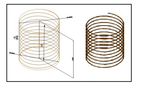
The schematic diagram of the conical coil geometry illustrated in Figure 1 with dimensions.
Figure 1. Schematic diagram of the conical coiled tubes
2.2 Design of helical coil
In this work, the following equations are used to establish the input variables that are additionally employed in the construction of the helical coil condenser [16].
The coil length and height in order to produce N turns;
$L=N \sqrt{\left(\pi d_t\right)^2+P^2}$ (4)
$H=N\left(S+d_t\right)$ (5)
(a) Helical coil
(b) Traditional coil
Figure 2. Schematic diagram of (a) helical and (b) traditional coiled tubes
This heat exchanger's pitch, which represents the distance across the successive coil turns:
$P=1.25 \, d_t$ (6)
Which is a typical designing number for these kinds of heat exchangers [17].
The schematic diagram of the helical and traditional coil is shown in Figure 2.
The conical and helical coil condenser for this work is designed so that it has the same surface area (πdtL) as the traditional condenser and designed parameters were selected to be suitable to the dimensions (width and height) of traditional condenser.
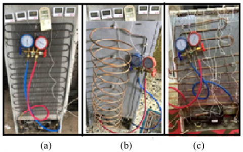
The test setup, shown in Figure 3, was designed for comparing the efficiency of a housing refrigerator's of helical and conical coil condensers with that of a standard condenser. AN assembly includes data-loggers model UT331+, a k-type thermocouples, an energy meter, and pressure gauges were used in for measurements. which involve sensors for dew-point temperature, relative humidity, and temperatures. Software configures the device's operation, including the necessary measurement time and the high and low temperature alarm readings, among other things. The instrument may be taken out after the measurement period in order to move the data to a computer for additional analysis. R134a has been used as the refrigerant in 165-lit refrigerators for the tests. The conical and helical condenser for this work is made of copper material with 11 numbers of turns. The description of the devices used in experimental setup are presented in Table 1. For the experimental setting of the conventional household refrigerator, the following procedure is used. The next step is to perform leakage tests using soap solution to test the pressure in the condenser and evaporator as well as to check purging every day for 12 hours. The results show that there are no leaks, which means that this study must be completed in order to conduct other experiments.
Turn on the refrigerator, observe it for an hour, record the temperature and pressure at each area, and place the dataloggers on the middle shelve within the refrigerator to record the temperature and relative humidity throughout the period of operation. Temperature pressure gauge and energy meter readings are used to assess how well the current system-a typical refrigerator-performs. then refrigerant is released and helical condenser is situated at capillary tube's inlet. After charging the refrigerator with R-134a, the efficiency was evaluated for both helical and conical condenser tubes.
Figure 3. Refrigerator of different geometries of the condenser coiled: (a) TC, (b) HC, and (c) CC-Refrigerator
Table 1. Technical description of sensors and devices
|
Device |
Description |
|
Thermocouple |
Type-k, range: -20℃-70℃ Resolution: ±0.5℃ |
|
Pressure gage |
Type bourdons, Resolution: (±0.05 bar) |
|
Dataloggers |
model UT331+ Resolution: ±0.5℃ Temperature: 0.1℃ Humidity: 0.1% RH |
|
Energy meter |
Modern industry of high precision |
The refrigerator designs that were tested under the identical operating conditions as those shown in Table 2 were as follows. The outdoor temperature is to be kept at 23℃ (±0.5℃) and 45% relative humidity during the testing period. The system reaches steady state condition at 180min.
1). TC -Refrigerator - with Traditional Coil condenser
2). HC -Refrigerator - with Helical Coil condenser
3). CC -Refrigerator - with Conical Coil condenser
The dimensions of condenser coiled geometries are presented in Table 3, and Figure 3 shows the refrigerators tested with HC and CC equipping with thermocouples. The duration of the experimentation for each refrigerator was when operated 8-hour shift 24-hours.
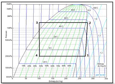
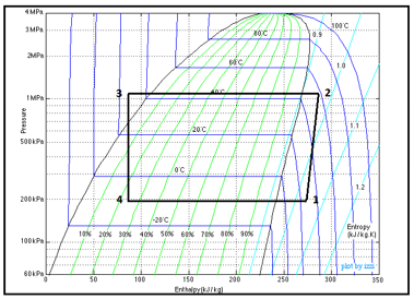
Using a p-h diagram and the cool-pack program [18], the refrigerant enthalpy for each step in the cycle was calculated and drawn as seen in Figure 4 for TC, HC, CC-Refrigerator, respectively.
Table 2. The dimensions of condenser coiled geometries
|
Coil Type |
Dimensions (mm) |
|
|
Traditional (TC) |
L=5640, H=490, DC=430 |
|
|
Helical (HC) |
H=490, DC=200, S=40 |
|
|
Conical (CC) |
H=390, DL=630, DC=230 |
|
Table 3. The operating parameters of different geometries of condenser coiled
|
Parameter |
Specification |
|
|
Evaporator pressure |
13.5 bar |
|
|
Condenser pressure |
0.2 bar |
|
|
mr |
0.01 kg/s |
|
(a) TC-Refrigerator
(b) HC-Refrigerator
(c) CC-Refrigerator
Figure 4. P-h diagram for different geometries of the condenser coiled
The following equations are used to determine the performance of a household refrigerator [19]:
Refrigerating effect,
$\mathrm{q}_{\mathrm{abs}}=\mathrm{h}_1-\mathrm{h}_4$ (7)
Refrigerant mass flow rate,
$\mathrm{E}-\mathrm{H}=\left(\mathrm{h}_{\mathrm{c}, \mathrm{o}}-\mathrm{h}_{\mathrm{c}, \mathrm{i}}\right) * \mathrm{~m}_{\mathrm{r}}$ (8)
where, E is the electric power consumption in the compressor and H is a percentage of heat loss through compressor [15], in this work taken as (6%) of E.
Compressor work,
$\mathrm{W}_{\mathrm{c}}=\mathrm{h}_2-\mathrm{h}_1$ (9)
Heat rejected from the condenser,
$\mathrm{q}_{\mathrm{rej}}=\mathrm{h}_2-\mathrm{h}_3$ (10)
where, h1, h2 are the enthalpy at compressor inlet and outlet and h3, h4 is the enthalpy at condenser outlet and evaporator inlet, respectively as presented in Figure 4.
Coefficient of performance,
$\mathrm{COP}=\frac{\text { Refrigerating Effect }}{\text { Compressor Work }}$ (11)
An uncertainty is a way to gauge how good a result is. It is impossible to assess the value's suitability as a foundation for decisions on the quality of scientific research without such metrics. Because of uncertainty, association with any primary measurements will propagate through the calculations and introduce uncertainty in derived quantities.
According to Moffat's theory [20], the uncertainty can be estimated using the root summation square of the impacts of each unique input.
Let the result R be a function of independent variables $(v 1, v 2, \ldots, v n)$.
$\mathrm{R}=\mathrm{R}(v 1, v 2, \ldots, v n)$ (12)
For small variations in the variables, the relation can be expressed as:
$\delta \mathrm{R}=\frac{\partial R}{\partial v 1} \delta_{v 1}+\frac{\partial R}{\partial v 2} \delta_{v 2}+\cdots \ldots \ldots+\frac{\partial R}{\partial v n} \delta_{v n}$ (13)
$\mathrm{S}_{\mathrm{R}}=\sqrt{\left(\frac{\partial \mathrm{R}}{\partial v_1}\right)^2 \mathrm{~S}_{\mathrm{v} 1}^2+\left(\frac{\partial \mathrm{R}}{\partial \mathrm{v}_2}\right)^2 \mathrm{~S}_{\mathrm{v} 2}^2+\cdots+\left(\frac{\partial \mathrm{R}}{\partial v_{\mathrm{n}}}\right)^2 \mathrm{~S}_{\mathrm{v} 2}^2}$ (14)
This method calculates the uncertainty associated with the measurement and also with the derived variables, but if a variable is measured and there are independent sources of error, then the final uncertainty in measurement is defined as:
$\mathrm{S}_{\mathrm{R}}=\sqrt{\mathrm{S}_1^2+\mathrm{S}_2^2+\cdots+\mathrm{S}_{\mathrm{n}}^2}$ (15)
The temperature data from the thermocouple, the heat exchanger's dimension, and the mass flow rate were all regarded to be the measurable data that had quantified uncertainty. In accordance with the manufacturer, there is a 0.01 mm uncertainty between the interior and exterior tube diameters that could be disregarded. Additionally, it was estimated that the uncertainty of water's physic parameters (k and Cp) was 0.1% based on thermodynamics tables. The uncertainty for mr, qrej, and COP including all experimentations using the above equations was 6%, 2.5%, and 2.1%, respectively.
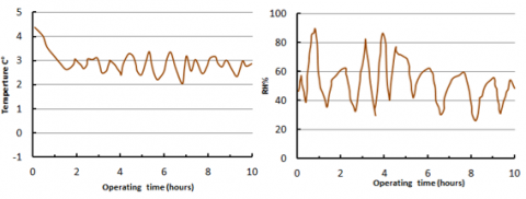
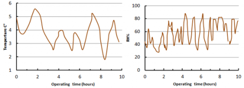
Figure 5 confirms that the temperature of fresh. food, which is 3.1℃, is attained in 60 minutes of operation of the CC-Refrigerator, while it's become 4.6℃ for the TC-Refrigerator and 3.9℃ for the HC-Refrigerator, see Figures 6 and 7. Also, the relative humidity CC-Refrigerator have been fluctuated around 45% as clear in Figure 5 while it's fluctuated around 60% for the TC-Refrigerator and 50% for the HC-Refrigerator. Therefore CC-Refrigerator has a better distribution of fresh food temperature and relative humidity when tested for 24-hour cycle.
Figure 5. Fresh food temperature and relative humidity for CC-Refrigerator
Figure 6. Fresh food temperature and relative humidity for HC-Refrigerator
Figure 7. Fresh food temperature and relative humidity for TC-Refrigerator
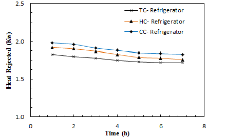
The heat rejection variation over time is shown in Figure 8 based on experimental calculations for three condenser configurations (TC, HC, CC- Refrigerator). The amount of heat transferred by the refrigerant from the cold side (cooling space) to the warm side (ambient air) through the condenser coil is directly related to the heat load in the evaporator and compressor work. The temperature difference between the refrigerant and the cold space decreased over time, causing a reduction in the heating load in the evaporator over time, until the steady state condition stated. As a result, the rejected heat reduced steadily over time. As shown in Figure 8, it is observed that the heat rejected from the HC exceeds that of the TC by approximately 9.9% and from CC by about 14.3%.
Figure 8. Heat rejected vs. time for all type of condenser
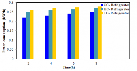
Various condenser shapes indicate the heat rate of exchange has increased. Figure 4 illustrates how the centrifugal force caused by the tube's curvature leads to the production of a secondary flow that increases the rate of heat transfer, increasing sub-cooled after the condenser and superheating after the evaporator. When employing helical and conical coil condensers, which provide the maximum refrigerating effect and eventually improve the coefficient of performance of a domestic refrigerator, subcooling of refrigerant also increases as heat transfer rate increases. A refrigeration system's COP can be raised by either raising the refrigerating effect or lowering the compression work. The coefficient of performance is calculated as the ratio of the refrigerating effect to the compression work. A reduction in compressor working cycle of approximately 2.7% with HC refrigerators and 3.6% with CC refrigerators results from such an improvement in COP and cooling capacity. The second law of thermodynamics, often known as the law of entropy, causes the cooling effect to diminish over time, which causes the performance coefficient to decline over time as a result. However, at steady state circumstances, the performance coefficient exhibits the same behavior across time. As shown in Figure 9 when using HC and CC-Refrigerator instead of TC- Refrigerator, COP increased by 10.1% for HC-coil and by 11% for CC-coil. Figure 10 shows the enhancement percentage in COP for all types of condensers through 125 min time interval. Therefore, the provision of HC and CC-refrigerator is useful due to more heat transfer sub cooling occurs at the exit of the condenser for HC and CC-refrigerator and hence the performance of the system increases. The results show in Figure 11 that CC-refrigerator attains lowest power consumption than HC and TC by about 10% and 16.6% respectively under same operating conditions.
When evaluated at 23℃ ambient for a 24-hour cycle, Figure 12 shows that the configuration of (CC-condenser) had higher energy efficiency for 25% runtime.
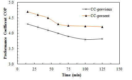
Moreover, from Figure 13 it is clear that the CC refrigerator has a greater COP than the HC and TC refrigerators, the other two refrigerators. Also, the CC-Refrigerator consumed the least amount of energy. This study shows that altering the condenser's coil design can significantly affect the energy and performance of refrigerators. Under the conditions of the outside temperature, thermal load, or the raw food compartment temperature, energy utilization can be increased by up to 20%. The present experimental results for helical coil HC performance coefficient COP have been compared with literature [2] to ensure the validity and accuracy of the experimental measurement data. As shown from Figure 14 that the deviation between results of present work and literature less than (±8.5%), while using conical coil CC-condenser in domestic refrigerator is a novel work that present work addressed.
Figure 9. Coefficient of performance vs. time for all type of condenser
Figure 10. Enhancement in COP for all type of condenser
Figure 11. Comparison of power consumption for all type of condenser
Figure 12. Energy consumption in refrigerators for all type of condensers
Figure 13. Coefficient of performance vs. energy consumption for all type of condenser
Figure 14. Comparison of performance coefficient for HC-refrigerator with previous work [2]
The present study investigates experimentally the impact of different condenser geometries on the thermal performance of domestic refrigerators of 165 liters capacity under the same operating conditions. By incorporating the CC and HC- condenser in the refrigerator the COP enhanced by 10.1% when using HC-Refrigerator and 11% when using CC-Refrigerator and reduction in compressor power consumption by 10% when using HC-Refrigerator and 16.6% when using CC-Refrigerator for 25% runtime when tested at 23℃ ambient temperature for 24-hour cycle. Furthermore, the findings indicate that the heat rate transfer increased, which implemented the HC-and CC-Refrigerator compared to TC-Refrigerator leading to increases the subcooled of the refrigerant after the condenser and the refrigeration effect which enhance the system performance. As a result, it was ensuring that the fresh food air temperature in the new configurations HC-and CC-Refrigerator within a favorite range of temperature values. Finally, it is concluded by change the shape of existing geometry to CC and HC - condenser the coefficient of performance is increased and heat transfer rate is increased and power consumption is decreased, so the novel design of conical and helical condenser which adopted in this work are superior in domestic refrigerator.
|
dt |
tube inner diameter, mm |
|
Dc |
coil diameter, mm |
|
DL |
coil large diameter, mm |
|
DS |
coil small diameter, mm |
|
h1 |
enthalpy, kJ/kg |
|
H |
condenser high, mm |
|
S |
coil spacing, mm |
|
P |
tube pitch, mm |
|
L |
coil length, mm |
|
mr |
mass flow rate, kg/s |
|
N |
number of loops |
|
Abbreviations |
|
|
TC |
Traditional coil |
|
CC |
Conical coil |
|
HC |
Helical coil |
[1] Sunny, S.P., Mhaske, S.D., Parikh, Y.B. (2014). Numerical simulation of a tube in tube helical coiled heat exchanger using CFD. International Journal of Applied Engineering Research, 9(18): 5209-5220.
[2] Subbaiah, S.R., Nagamani, G.V. (2015). Effect of condenser coil diameter on performance of a domestic refrigerator. International Journal & Magazine of Engineering, Technology, Management and Research, 2(12).
[3] Hussain Vali, R., Yagnasri, P., Reddy, S.N.K. (2016). Performance analysis of VCR system with varying the diameters of helical condenser coil by using R-134a refrigerant. International Journal of Engineering Sciences & Research Technology, 5(2): 5209-5220. http://doi.org/10.5281/zenodo.46535
[4] Elazm, M.A., Ragheb, A.M., Elsafty, A.F., Teamah, M.A. (2013). Numerical investigation for the heat transfer enhancement in helical cone coils over ordinary helical coils. Journal of Engineering Science and Technology, 8(1): 1-15.
[5] Missaoui, S., Driss, Z., Slama, R.B., Chaouachi, B. (2022). Experimental and numerical analysis of a helical coil heat exchanger for domestic refrigerator and water heating. International Journal of Refrigeration, 133: 276-288. https://doi.org/10.1016/j.ijrefrig.2021.10.015
[6] Borikar, S.A. (2015). Performance evaluation and economic analysis of solar powered refrigerator. Journal of Basic and Applied Research International, 25(4): 197-206.
[7] James, S.J., Evans, J., James, C. (2008). A review of the performance of domestic refrigerators. Journal of Food Engineering, 87(1): 2-10. https://doi.org/10.1016/j.jfoodeng.2007.03.032
[8] Borikar, S.A., Wankhede, U.S. (2008). Experimental analysis of solar refrigeration system. International Refrigeration and Air Conditioning Conference.
[9] Neto, I.D.M., Padilha, A., Scalon, V.L. (2009). Refrigerator COP with thermal storage. Applied Thermal Engineering, 29(11-12): 2358-2364. https://doi.org/10.1016/j.applthermaleng.2008.12.003
[10] Marques, A.C., Davies, G.F., Evans, J.A., Maidment, G.G., Wood, I.D. (2013). Theoretical modelling and experimental investigation of a thermal energy storage refrigerator. Energy, 55: 457-465. https://doi.org/10.1016/j.energy.2013.03.091
[11] Mahdy, A.T., Naji, Z.H., Ibrahim, S.H. (2024). Design and construction heat recovery unit using rejected heat from condenser of fridge. AIP Conference Proceedings, 3002(1). https://doi.org/10.1063/5.0206917
[12] Kshirsagar, M.P., Kansara, T.J., Aher, S.M. (2014). Fabrication and analysis of tube-in-tube helical coil heat exchanger. International Journal of Engineering Research and General Science, 2(3): 66-75.
[13] Cheng, W.L., Yuan, X.D. (2013). Numerical analysis of a novel household refrigerator with shape-stabilized PCM (phase change material) heat storage condensers. Energy, 59: 265-276. https://doi.org/10.1016/j.energy.2013.06.045
[14] Cheng, W.L., Ding, M., Yuan, X.D., Han, B.C. (2017). Analysis of energy saving performance for household refrigerator with thermal storage of condenser and evaporator. Energy Conversion and Management, 132: 180-188. https://doi.org/10.1016/j.enconman.2016.11.029
[15] Suryawanshi, V.V., Ghodake, N., Patil, O., Lomate, S., Nerkar, S.G. (2021). Design & analysis of helical-coil heat exchanger. International Journal of Engineering Research in Mechanical and Civil Engineering, 6(8): 28-33
[16] Jakobsen, A., Rasmussen, B.D., Skovrup, M.J., Andersen, S.E. (2001). Cool pack-A collection of simulation tools of refrigeration. Department of Energy Engineering Technical University of Denmark. https://www.coursehero.com/file/168344617/CoolPack-Tutorialpdf/.
[17] Abdelghany, M.T., Elshamy, S.M., Salem, M.R., Abdellatif, O.E. (2020). Enhancement the thermal performance of a shell and coil heat exchanger with different coil geometries: Comparative experimental investigation. Engineering Research Journal, 1(43): 57-65.
[18] Slama, R.B. (2009). Thermodynamic heat water by the condenser of the refrigerator. In CONV-09. Proceedings of International Symposium on Convective Heat and Mass Transfer in Sustainable Energy. Begel House Inc. http://doi.org/10.1615/ICHMT.2009.CONV.840
[19] Barrak, A.S., Saleh, A.A.M., Naji, Z.H. (2021). A heat recovery device using oscillating heat pipe with circular and elliptical tubes. International Journal of Automotive and Mechanical Engineering, 18(1): 8442-8453. https://doi.org/10.15282/ijame.18.1.2021.04.0639
[20] Moffat, R.J. (1988). Describing the uncertainties in experimental results. Experimental Thermal and Fluid Science, 1(1): 3-17. https://doi.org/10.1016/0894-1777(88)90043-X