Farah L. Rauf![]() | Mahdi Sabbar Whaib
| Mahdi Sabbar Whaib![]() | Mohammed Elwi*
| Mohammed Elwi*![]()
© 2025 The authors. This article is published by IIETA and is licensed under the CC BY 4.0 license (http://creativecommons.org/licenses/by/4.0/).
OPEN ACCESS
The objective of this study was to research the flexural behavior of damaged reinforced concrete (RC) beams strengthened with textile-carbon fiber (TCF) reinforcement. Thirteen beams were cast, involving a control beam, and exposed to monotonic loading tests. The beams adhered to ACI 318-14 guidelines to avoid flexural failure and were evaluated under varying damage levels (0%, 45%, 55%, and 70%). TCF mesh layers, bonded using sikadure-330, were applied to enhance performance. Finite element modeling using ABAQUS with a concrete damaged plasticity methodology was employed for analysis, with results associated with experimental data. The decisions demonstrated that TCF reinforcement significantly improved flexural capacity, increasing final load by 40.41% to 63.02% across different beam groups. Beams strengthened with two TCF layers exhibited a notable 56% increase in load-bearing capacity, indicating a cost-effective and effectual reinforcement manage. The study revealed developed crack resistance, load-deflection characteristics, and power absorption due to TCF application. The limited element model closely replicated experimental outcomes, stressing its reliability in simulating concrete's elastic and plastic responses under various stress conditions. This research stresses the potential of TCF as a promising logic for retrofitting and reinforcing damaged RC constructions, offering valuable insights into optimizing structural rehabilitation strategies.
textile-carbon fiber (TCF) layers, ABAQUS software, finite element analysis, strengthened concrete beam, non-linear structural collapse
Reinforced concrete (RC) elements may require reinforcement due to various issues that can arise during typical building usage, such as increased live loads or structural damage. There are diverse methods available to enhance load-bearing capacity, with a recent option being the utilization of textile-carbon fiber (TCF) for concrete reinforcement. TCF is a versatile technique suitable for addressing various active forces, including bending, shear, torsion, and axial forces [1]. The principal aim of this research was to examine the bending performance of damaged reinforced concrete beams that underwent reinforcement with textile carbon mesh and were bonded with sikadure-330, considering various degrees of damage (0%, 45%, 55%, and 70%). Thirteen beams were cast and subjected to monotonic loading tests, with one beam serving as the control [2]. These beams adhered to ACI 318-14 guidelines to prevent flexural failure. The research demonstrates the effectiveness of TCF sheets in reinforcing damaged concrete structures, playing a substantial role in the strengthening and restoration of the beams when considering parameters like first fracture load, ultimate load, crack patterns, and load deflection [3]. The findings reveal that TCF reinforcement significantly increased the flexural capacity of all the reinforced beams. The percentage increases in ultimate loads for groups A, B, C, and D ranged from 40.41% to 63.02%. Notably, group B, with three strengthening layers, exhibited a remarkable 61-point increase. The application of TCF materials substantially improved the ultimate load-bearing capacity by 8% to 62%, along with a corresponding increase in the ultimate mid-span deflection proportion by 12% to 74%. The two-layer TCF beam emerged as the most effective method, resulting in a remarkable 56% increase in maximum load-bearing capacity. This approach appears to be cost-effective and sufficient for enhancing flexural capacity, considering its price. TCF demonstrates significant promise as a method for reinforcing and retrofitting reinforced concrete structures, particularly in enhancing their flexural strength [4]. The study utilized the ABAQUS program and finite element modeling with a concrete damaged plasticity approach to simulate the behavior of reinforced concrete bars. The numerical results closely matched experimental data, affirming the accuracy of theoretical calculations, and serving as a valuable complement to laboratory investigations. Modeling reinforced concrete in finite element software can be challenging. A proficient finite element model should precisely capture the elastic and plastic responses of concrete when subjected to both compressive and tensile forces [5]. This entails accounting for the complete compressive behavior, encompassing both elastic and inelastic components, which includes accommodating strain softening characteristics. Furthermore, when modeling concrete under tensile loads, it is crucial to account for phenomena like tension softening, tension hardening, and the localized bonding effects that occur within reinforced concrete components. The development of a finite element model often requires thorough material testing to incorporate these behaviors into the existing finite element software packages [6].
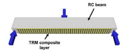
Li et al. [7] presented an updated examination regarding the utilization of textile-reinforced composites (TRC) in fortifying concrete structures. This comprehensive review conducted by Hu et al. [8] commences by addressing the tensile properties and bonding characteristics inherent to TRC. Subsequently, it delves into critical factors and furnishes an overview of 20 investigations that have harnessed TRC for the purpose of retrofitting concrete structures or enhancing the resistance of reinforced concrete members to various forces such as bending, tension, confinement, and seismic actions. One prevalent application involves the adhesion of TRC layers to the tensile surface, conventionally situated beneath a slab or the underside of a beam (as exemplified in Figure 1), to bolster these elements against the effects of flexural loading. Notably, while the majority of experiments in these studies employed cylindrical specimens composed of unreinforced concrete, with dimensions measuring 150 mm in diameter and 300 mm in height, other configurations such as rectangular column-type elements ranging from 150 mm×150 mm to 250 mm×350 mm and varying heights spanning from 300 to 1,500 mm were also subjected to scrutiny. Diverse types of fiber fabrics, including AR glass, basalt, aramid, carbon, and PBO, were deployed in these investigations, with PBO and carbon textiles emerging as the most frequently explored materials. The authors underscore the promising potential of textile-based composites in the realms of earthquake-resistant design and the reinforcement of concrete structures. These themes are increasingly gaining attention within the global scientific community. Looking ahead, the authors propose that forthcoming research in this domain should prioritize endeavors aimed at augmenting textile reinforcement, evaluating the durability of strengthening systems, particularly in conditions characterized by elevated temperatures, and the formulation of design standards that seamlessly integrate within established design principles [8-10].
Afzal [11] conducted a thorough examination of the impact of slurry type on the effectiveness of textile-reinforced composites (TRC) through the manipulation of fabric type and the number of fabric layers. The analysis conducted in this study involved a total of nine medium-sized reinforced concrete (RC) beams. These beams were subjected to 4-point bending tests with simple support. Among the collection of beams, a single beam was selected as the control specimen and subjected to testing in its initial compact condition, without any supplementary strengthening. The remaining beams were methodically reinforced using different combinations of parameters. The parameters utilized in this study involved the application of cement-based mortar devoid of polymers, the manipulation of the number of reinforcing layers (comparing 3 layers to 6 layers), and the adoption of basalt fibre with a smaller mesh size in contrast to fibre glass fabric with a bigger mesh size [12]. The findings of their inquiry revealed that the incorporation of TRC reinforcement resulted in a significant enhancement in the flexural capacity of all the reinforced beams. The observed increase in flexural capacity varied between 7.4% and 37.4%, depending on the precise combinations of fabric type, number of layers, and mortar type. Figure 2 presents a comprehensive illustration that effectively represents the geometric characteristics and reinforcement details of the reinforced concrete (RC) beams. In conclusion, the study conducted by Umbricht et al. [13] sheds light on the significant role played by the slurry type and the configuration of TRC reinforcement in augmenting the flexural performance of reinforced concrete beams. Their findings provide valuable insights into the optimization of the design and effectiveness of TRC applications in the field of structural engineering [14, 15]. In the context of concrete construction and engineering, a concrete mix refers to the specific combination of materials and their proportions that are carefully selected and mixed together to achieve desired properties and performance in the final concrete product. The mix design process is a critical step in ensuring that the resulting concrete will possess the required compressive strength and workability for its intended application. In accordance with ASTM C496-04, which is a standard specification for concrete workability, tests are conducted to evaluate the compressive strength of the concrete mix at specified time intervals, typically seven and 28 days. The primary objective of mix design is to strike a balance between achieving the necessary structural strength while also ensuring that the concrete is workable and can be easily placed and finished during construction. Achieving the right mix design is crucial because it impacts the concrete's durability, resistance to environmental factors, and overall performance in service [16]. Table 1 is a representation of the specific proportions of the constituent materials used in the concrete mixtures. These materials typically include cement, aggregates (such as sand and gravel or crushed stone), water, and often supplementary cementitious materials or chemical admixtures. The table provides a detailed breakdown of the quantities or percentages of each material used in the mix. These proportions are calculated and adjusted to meet the project's specific requirements and performance criteria. By following a well-designed mix, engineers and concrete producers can control the properties of the concrete, including its strength, workability, durability, and other factors, to ensure that it meets the needs of the construction project (Table 2). This mix design process is a fundamental aspect of concrete technology and is essential for achieving high-quality and reliable concrete structures in various construction applications [17].
Figure 1. Flexural strengthening of an RC beam with TRC
Figure 2. RC beams geometry and reinforcement details (mm)
Table 1. The proportions of materials used in mixtures [3, 6]
|
Mix |
Cement (kg) |
Sand (kg) |
Gravel (kg) |
RA (kg) |
SBR (%) |
PPF (%) |
w/c Ratio |
|
Mix1 |
6 |
10.5 |
16 |
0 |
0 |
0 |
3 |
|
Mix2 |
6 |
10.5 |
0 |
16 |
0 |
0 |
3 |
|
Mix3 |
6 |
10.5 |
0 |
16 |
0 |
0 |
3 |
|
Mix4 |
6 |
10.5 |
0 |
16 |
2 |
0 |
3 |
|
Mix5 |
6 |
10.5 |
0 |
16 |
0 |
1 |
3 |
|
Mix6 |
6 |
10.5 |
0 |
16 |
0 |
2 |
3 |
Table 2. The compressive strength, splitting tensile strength, and concrete pipe test [4, 5]
|
Mix |
Average Compressive Strength (MPa) |
Average Splitting Tensile Strength (MPa) |
Concrete Pipe Test (MPa) |
|
Mix 1 |
30.3 |
3.1 |
34.8 |
|
Mix 2 |
21.6 |
1.9 |
21.35 |
|
Mix 3 |
23.7 |
2.4 |
27 |
|
Mix 4 |
26.1 |
2.75 |
30.9 |
|
Mix 5 |
21.9 |
2.78 |
31.2 |
|
Mix 6 |
22.5 |
3.2 |
35.9 |
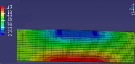
A finite element model is a numerical representation used in structural analysis and engineering simulations to understand how a structure or component responds to various loads and conditions. It divides complex structures into smaller, more manageable elements or segments, allowing engineers to perform detailed analyses and make predictions about how the structure will behave. Material Properties: In the particular specimen being discussed, several materials are employed, including concrete, steel bars, and steel plates (as shown in Figure 2). Each of these materials has unique properties that are essential for accurately modeling and simulating the behavior of the structure. Steel Reinforcing Bar: For the steel reinforcing bar, a material with specific characteristics is chosen. In this case, a versatile yet perfectly plastic material model is utilized. This means that the steel bar can undergo deformation and yield (plasticity) under load but doesn't exhibit permanent deformation beyond a certain point. It has equal properties in both tension and compression [18]. Throughout the analysis, the steel bar is treated as a uniaxial material, meaning its behavior is simplified along one axis (as illustrated in Figure 3). This simplification allows for efficient modeling while retaining the essential characteristics of the steel bar.
Rebars and Concrete Interaction: In this finite element model, the interaction between the steel reinforcement bars (rebars) and the concrete is a critical consideration. The rebars are essentially represented as one-dimensional strain elements, which means they can be individually placed within the concrete structure. Their behavior is similar to that of an elastic-plastic material, indicating that they can both deform elastically and undergo plastic deformation under certain loads. Importantly, the model treats the behavior of the rebars and the concrete cracking phenomenon as separate entities [19, 20]. This approach allows for a more realistic representation of how the load is transferred from the concrete to the rebars and vice versa when the structure is subjected to stress.
Tension Stiffening: To account for the transfer of load across concrete cracks and the effect of the rebars, the concept of "tension stiffening" is introduced into the concrete cracking model. Tension stiffening refers to the phenomenon where the presence of reinforcing bars in concrete helps to maintain some degree of stiffness and load-carrying capacity even after the concrete has cracked. It is an essential consideration in accurately predicting the structural behavior of reinforced concrete elements, as it accounts for the redistribution of forces when cracks form. The finite element model being discussed incorporates various material properties and behaviors to simulate the response of concrete structures reinforced with steel bars. This approach allows engineers to analyze how the structure will perform under different conditions and loads, providing valuable insights for the design and assessment of reinforced concrete elements.
(a) Finite element modeling
(b)Steel bar stresses
(c) Concrete stresses
(d) Concrete meshed model
Figure 3. Finite element model
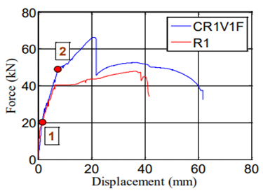
In this study, we undertake an in-depth examination of the test outcomes acquired from every individual specimen. The test results cover a complete variety of data, comprising load vs displacement curves, steel strain measurements, and concrete strain values. Each of these data points is evaluated separately. The load values were accurately measured using a load cell that is incorporated within the Instron testing machine. Furthermore, we conducted calculations and provided the mean values of steel strain measurements obtained from the two-foot-long reinforcement bars. In addition to the quantitative findings, our study offers comprehensive analysis of the observed fracture patterns and modes of failure displayed by each individual specimen. In order to gain a thorough understanding of the impact of the parameters being investigated, subsequent portions of this study will be dedicated to analyzing their effects on the observed quantities. This discussion is pivotal in unraveling the intricate relationship between the studied variables and the resulting test outcomes. Moreover, we offer a detailed and thorough analysis of the test results, providing a nuanced understanding of the specific modes of failure and crack patterns witnessed in each individual specimen. To illustrate the practical implications of our findings, let's focus on the example of the C-R1-V1-F bar. In this particular case, we employed 2D10 as the primary longitudinal reinforcement, enhancing it with a carbon Textile-Reinforced Mortar (TRM) system comprising a single layer of carbon material (EA)1=12.56 kk/mm. In Figure 4(a), we present the load-displacement relationship for this specimen, juxtaposed with its corresponding control example, providing a clear visualization of how the load varies with displacement during testing [10, 11].
(a)
(b)
(c)
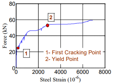
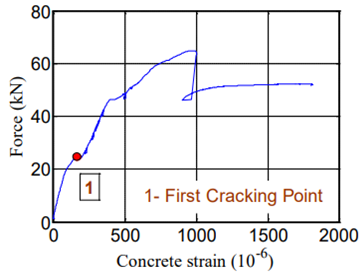
Figure 4. The outcomes of specimen C-R1-V1-F: (a) The relationship between load and displacement; (b) The connection between load and steel strain; (c) The correlation between load and concrete strain [11]
(a)
(b)
(c)
Figure 5. Load-displacement, steel strain, and concrete strain relationships for sample C-R1-V2-F
Furthermore, Figures 4(b) and (c) in our discussion reveal the interplay between load and both steel and concrete strains, offering valuable insights into the material responses and behaviors under the influence of applied loads. In summary, this part serves as a pivotal platform for the comprehensive analysis and interpretation of our test results, contributing significantly to our understanding of the behavior and performance of the tested specimens under varying conditions. By dissecting the effects of the studied parameters, we gain valuable insights into the structural response and integrity of the materials and systems under scrutiny.
A different arrangement was utilized for the C-R1-V2-F pillar specimen. This specimen employed 2D10 as its primary longitudinal support and incorporated reinforcement with a carbon Textile-Reinforced Mortar (TRM) system consisting of two layers of carbon material (EE)c2=25.12 kk/mm. The chapter presents various aspects of the performance of this specimen. Figure 5(a) portrays the load-displacement relationship for this specimen, as well as its corresponding control example. This graph effectively depicts the variations in load with respect to displacement during the testing procedure [11].
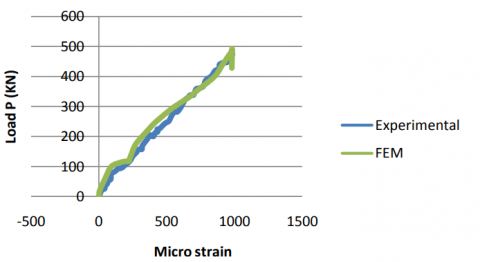
Moreover, Figures 5(b) and (c) offer insights into the correlation between load and both steel and concrete strains. These figures illustrate the response of these materials when subjected to applied loads. Notable observations from this specimen include the point of yielding, which occurred at 51.64 kN, and the recorded displacement at the yield load, The displacement measured was 7.74 mm, and the maximum recorded load reached 72.94 kN, followed by a sharp decline in the load. The increase in the maximum load was significant, marking a notable 52.29% rise when contrasted with the control specimen. These findings offer valuable insights for analyzing and discussing the behavior and performance of this particular specimen examined in the study [11]. In this section, we present a comparative assessment between the compressive strain and load deflection data sourced from both the finite element analysis and the experimental measurements for the concrete situated at the center of the upper surface of the specimen. This comparative evaluation is visually represented in Figure 6. It is worth highlighting that there is a robust concurrence and alignment between the outcomes of the finite element analysis and the experimental data pertaining to compressive strain within the concrete material [10].
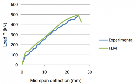
The deflection measurement was executed at the midpoint of the foot of the pillar, specifically at midspan. Figure 7 presents an illustration of the load-deflection curve for the pillar, exhibiting both the experimental and numerical data. In general, there exists a robust agreement between the load-deflection curve obtained from the numerical analysis and the experimental data, emphasizing the coherence between the two sets of results [10]. Figure 5 displays the outcomes obtained from testing specimen C-R1-V2-F, showcasing the relationship between various parameters. The first graph illustrates the load versus displacement, highlighting the correlation between these two variables. The second graph demonstrates the load versus steel strain, shedding light on the connection between the load applied and the strain experienced by the steel material. Lastly, the third graph exhibits the load versus concrete strain, providing insight into the relationship between the load applied and the resulting strain in the concrete material.
Figure 6. Load-compressive strain for concrete
Figure 7. Load-deflection for the beam [10]
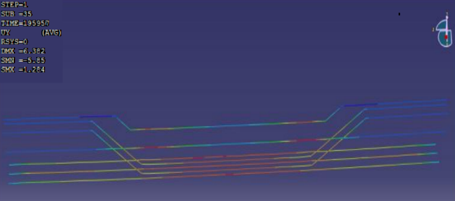
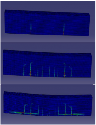
Figure 8. Crack patterns in process of analysis
The comparison between the concrete fracture patterns derived from the numerical simulation and those witnessed in the laboratory tests is presented in Figure 8. Typically, the onset of flexural fractures tends to transpire early at the midspan of the specimen. As the applied loads intensify, these vertical flexural fractures extend laterally from the midspan towards the supports. With greater applied loads, diagonal ductile fractures become discernible, adding to the intricacy of the fracture patterns. It is essential to emphasize that a substantial degree of correspondence and concurrence is evident between the results of the finite element analysis and the empirical data concerning the concrete fracture patterns [10].
This work has undertaken empirical and analytical examinations to investigate the application of Textile-Reinforced Mortar (TRM) in enhancing the flexural capacity of reinforced concrete beams. Two separate thermal resistance measurement techniques, specifically carbon TRM and PBO TRM, were employed as reinforcement materials. The primary aim of the study was to evaluate the influence of three primary variables, namely the steel reinforcement ratio, various TRM systems, and the volume fraction of materials. The objective of these investigations was to gain a comprehensive understanding of the behaviour exhibited by each TRM system, facilitating comparative comparisons between the two systems. The findings indicate that in both types of TRM systems, an augmentation in the reinforcement ratio led to a reduction in the ductility index. This behaviour is frequently observed in reinforced concrete beams with a larger percentage of reinforcement. Nevertheless, it was observed that there was a significant increase in the amount of energy absorbed by all specimens as the reinforcement ratio increased. Moreover, the present study presents a finite element model that possesses the capability to analyze the nonlinear response of reinforced concrete elements. The model underwent verification by comparing its results to experimental data that had been previously published in the literature. The outcomes of the model verification demonstrated a strong concurrence between the displacement, ductile strain of the primary reinforcement, compressive strain of the concrete, and fracture patterns acquired by finite element analysis and those determined from experimental testing. In conclusion, this study offers significant contributions to the understanding of the capabilities of TRM systems in augmenting the flexural capacity of reinforced concrete structures. The results underscore the significance of reinforcement ratios and the possibility for enhanced energy absorption. Furthermore, the verified finite element model provides a reliable tool for examining and forecasting the performance of reinforced concrete components subjected to bending loads, therefore serving as a significant asset for forthcoming investigations in the field of structural engineering.
[1] Koutas, L.N., Tetta, Z., Bournas, D.A., Triantafillou, T.C. (2019). Strengthening of concrete structures with textile reinforced mortars: State-of-the-art review. Journal of Composites for Construction, 23(1): 03118001. https://doi.org/10.1061/(ASCE)CC.1943-5614.0000882
[2] Koutas, L.N., Bournas, D.A. (2017). Flexural strengthening of two-way RC slabs with textile-reinforced mortar: Experimental investigation and design equations. Journal of Composites for Construction, 21(1): 04016065. https://doi.org/10.1061/(ASCE)CC.1943-5614.0000713
[3] Hussein, W.G.A., Mohammed, A.S., Elwi, M. (2022). The effect of dynamic load on tall building. Periodicals of Engineering and Natural Sciences, 10(3): 286-299.
[4] Fattah, M.Y., Waryosh, W.A., Al-Hamdani, M.A. (2015). Experimental and theoretical studies on bearing capacity of conical shell foundations composed of reactive powder concrete. Acta Geodynamica et Geomaterialia, 12(4): 411-426. https://doi.org/10.13168/AGG.2015.0037
[5] Danha, L.S., Abdul-Hussien, Z.A., Elwi, M. (2022). Evaluation of the behavior of tanks under seismic load. Periodicals of Engineering and Natural Sciences, 10(4): 130-139. http://doi.org/10.21533/pen.v10i4.3150
[6] Chen, Y., Ning, Y., Chen, X., Xuan, W., Zhu, X. (2023). Experimental and numerical investigation on the triaxial compressive behavior of steamed recycled aggregate concrete. Buildings, 13(2): 334. https://doi.org/10.3390/buildings13020334
[7] Li, L.J., Guo, Y.C., Liu, F., Bungey, J.H. (2006). An experimental and numerical study of the effect of thickness and length of CFRP on performance of repaired reinforced concrete beams. Construction and Building Materials, 20(10): 901-909. https://doi.org/10.1016/j.conbuildmat.2005.06.020
[8] Hu, H.T., Lin, F.M., Liu, H.T., Huang, Y.F., Pan, T.C. (2010). Constitutive modeling of reinforced concrete and prestressed concrete structures strengthened by fiber-reinforced plastics. Composite Structures, 92(7): 1640-1650. https://doi.org/10.1016/j.compstruct.2009.11.030
[9] Hussein, W.G.A., Al-Hamdani, M.A. (2018). Behavior of reinforced concrete beams composed of reactive powder strengthened by CFRP under repeated load. International Journal of Civil Engineering and Technology, 9(6): 944-954.
[10] Sinaei, H., Shariati, M., Abna, A.H., Aghaei, M., Shariati, A. (2012). Evaluation of reinforced concrete beam behaviour using finite element analysis by ABAQUS. Scientific Research and Essays, 7(21): 2002-2009. https://doi.org/10.5897/SRE11.1393
[11] Afzal, M.S. (2016). Strengthening of reinforced concrete beams with textile-reinforced mortars. Master's thesis, Qatar University.
[12] Abd-Al-Naser, M., Harba, I.S. (2023). Strengthening of reinforced concrete beams with textile-reinforced concrete. Civil and Environmental Engineering, 19(2): 596-609.
[13] Umbricht, G.F., Tarzia, D.A., Rubio, A.D. (2022). Determination of two homogeneous materials in a bar with solid-solid interface. Mathematical Modelling of Engineering Problems, 9(3): 568-576. https://doi.org/10.18280/mmep.090302
[14] Bejan, A. (2016). Constructal thermodynamics. International Journal of Heat and Technology, 34(1): S1-S8. http://doi.org/10.18280/ijht.34S101
[15] Bin Shibghatullah, A.S. (2023). Mitigating developed persistent threats (APTs) through machine learning-based intrusion detection systems: A comprehensive analysis. SHIFRA, 2023: 17-25. https://doi.org/10.70470/SHIFRA/2023/003
[16] Costa, T., Zarante, P., Sodré, J., Sens, M., Baar, R. (2013). Simulation of aldehyde formation in ethanol fuelled spark ignition engines. Engine Processes. Expert Verlag, Berlin.
[17] Bentley, R.E. (Ed.). (1998). The Theory and practice of thermoelectric thermometry. In Handbook of Temperature Measurement. Springer Science & Business Media, Vol. 3.
[18] Al Barazanchi, I.I., Hashim, W. (2023). Enhancing IoT device security through blockchain technology: A decentralized approach. SHIFRA, 2023: 10-16. https://doi.org/10.70470/SHIFRA/2023/002
[19] Burhanuddin, M. (2023). Assessing the vulnerability of quantum cryptography systems to emerging cyber threats. SHIFRA, 2023: 26-33. https://doi.org/10.70470/SHIFRA/2023/004
[20] Aljohani, A. (2023). Zero-trust architecture: Implementing and evaluating security measures in modern enterprise networks. SHIFRA, 2023: 60-72. https://doi.org/10.70470/SHIFRA/2023/008