Aqeel Majeed Breesam*![]() | Mohammed Jasim Mohammed
| Mohammed Jasim Mohammed![]()
© 2025 The authors. This article is published by IIETA and is licensed under the CC BY 4.0 license (http://creativecommons.org/licenses/by/4.0/).
OPEN ACCESS
The DiPPM approach has been suggested as a potential resolution to the issue of bandwidth usage that affects alternative PPM formats. The construction of DiPPM is straightforward as it employs a dual-slot mechanism for transmitting a single unit of pulse code modulation (PCM). As a new coding scheme, the public literature has little analysis and experimental outcomes. This especially addressed the implementation of DiPPM to alleviate the problem of current PPM formats' excessive bandwidth utilization. DiPPM suffers from the same three forms of pulse detection mistakes as conventional PPM schemes: incorrect slot, false alarm, and erasure. This article focuses on extensively improving the error performance of DiPPM by using low density parity check (LDPC) as forward error correction (FEC) codes. To systematically evaluate the effectiveness of DiPPM-encoded LDPC, the error performance of a non-coded DiPPM system with that of DiPPM-encoded and DiPPM-encoded Reed Solomon Code (RS) (another FEC) system, transmission efficiency, and bandwidth broadening are compared. The results confirm a clear improvement in the performance of DiPPM for fault detection LDPC operates at its optimum values. LDPC code provided more than 5.12 dB.
dicode pulse position modulation (DiPPM), forward error correction (FEC), low density parity check (LDPC) code, Reed Solomon (RS) code
The communication device uses a channel or transmission method, such as wired or wireless, to facilitate the transfer of data from the source to the receiving device [1]. The primary elements affecting the reliability of the data obtained are the channel and specifically the background noise present on the channel. In essence, noise is what causes signal interference and data transmission mistakes. An innovative method for improving interface performance in low-turbulence conditions is channel coding. In order to achieve this, several PPM format types have been suggested as optical communication coding systems in the literature. Take MPPM and DPPM, for instance. Due to its notable features, PPM is largely used in deep space optical communications, including elevated energy consumption, robust resistance against interference, and a heightened detection frequency. But because PPMs have a large bandwidth expansion factor, one of their biggest drawbacks is that their ultimate data rates are incredibly high [2]. Stated differently, the maximum line rate that may be achieved would restrict its use. Therefore, in scenarios when capacity is not required, these coding methods can be used to effectively construct direct lines for vision networks using fiberglass optic cables. Because optical fiber connections are inexpensive, they are frequently used in low-bandwidth magnetic logging networks. Sibley [3] created DiPPM as a novel coding scheme with greater properties over the PPMs suggested in order to address the bandwidth concern. More specifically, the DiPPM was created to address the PPM's primary difficulty with bandwidth dissipation.
In comparison to other adaptive codes, LDPC codes are commonly employed due to their ability to facilitate efficient and dependable transmission of information over broadband channels, even in the presence of deteriorating noise conditions. Hence, LDPC codes have the capability to function over several channels. However, as the block length gets smaller, these codes and procedures become less accurate and reliable. This signalling type exclusively transmits data updates, while signals containing static data are not compatible [4].
One of the most extensively researched areas in channel coding is LDPC codes, widely used in a wide range of communication and data storage systems, such as deep-space, wireless, optical, and magnetic recoding systems [5-10].
Deep space algorithms are extremely desirable for use in LDPC and PPM iterative demodulation systems because they can achieve output performance that is very close to the theoretical Shannon limit. The highest error-free data transmission rate that may be attained across a communication channel at a particular noise level when random data transmission defects are present is known as the Shannon limit [11, 12].
The Reed-Solomon code was developed by Reed and Solomon as a means to effectively manage the factors contributing to DiPPM error. Reed and Solomon demonstrated the superior effectiveness of DiPPM in detecting faults, hence improving packet error rate performance while using the RS technique for error detection. Moreover, the DiPPM errors discovered during transmission can be fixed with the MLSD error corrector [13]. Also proposed by Al-Nedawe et al. [13], Reed-Solomon eliminated sources of DiPPM inaccuracy to reduce the amount of transmission mistakes by a significant margin.
In order to address the DiPPM's error sources, LDPC is introduced for the first time in this study. For the LDPC code, the ideal DiPPM system parameters have been discovered. The metrics of photons per pulse and transmission efficacy were used to evaluate uncoded and coded DiPPM systems utilising RS codes.
To the authors' knowledge, there has been no exploration of the employment of DiPPM and LDPC code decoding approaches to address the issues related to bandwidth increase in PPM. For this reason, the main goal of this research is to integrate LDPC and DiPPM code for error mitigation in order to address the previously mentioned issue, while also examining the most effective LDPC configurations.
Due to a difficulty with bandwidth expansion, DiPPM was established to overcome PPM [3]. Thus, the DiPPM formats follows the same pattern of the PPMs formats. Analog signals that have been sampled digitally are represented using the pulse code modulation (PCM) technique. An analog signal's amplitude is periodically sampled by a (PCM) stream, which quantizes each sample to the closest value within a predetermined range of digital steps. DiPPM employs the PCM method in a single time and four time slots for interval amplification. The first slot receives a SET (S) pulse first, while the second slot receives a SET (S) pulse second. The second spot is filled with a RESET (R) pulse, and inter-symbol interference protection is placed in the third and fourth slots (ISI). PCM data from 0 to 1 is inverted to form the S pulse. But one-to-zero data is inverted to produce the R pulse. Figure 1 provides a visual representation of this. The top tracks of dicode, Figure 1 depicts the interpretation of PCM data by displaying the centre tracks of dicode and the bottom trace of DiPPM. Table 1 displays the DiPPM code alphabet [14].
Figure 1. Transformation of PCM data into dicode and DiPPM formats
Table 1. Alphabetical list of DiPPM codes
|
PCM |
DiPPM |
Symbol |
|
00 |
No Pulse |
N |
|
01 |
Set |
S |
|
10 |
Reset |
R |
|
11 |
No Pulse |
N |
No pulse is conveyed, even though the PCM data is unaltered. But when central decision detection replaced the slope detection method, inter-symbol interference was reduced. The complexity of the DiPPM decoder has been decreased through the use of a central decision tracking technique, enabled by the addition of a third-order Butterworth filter and an approachable Cascaded first-order preamplifier. The line an average of the DiPPM was twice as fast as the true data because there were no guard bits. Given its great efficacy and simplicity, it is conceivable that the DiPPM format will be able to vie with the PPM styles already in use in fiber optic grid.
The DiPPM format has been found to exhibit three distinct types of flaws, including erasure, wrong-slot, and false alert [15]. In the subsequent sections, a comprehensive analysis of these errors is presented, including an assessment of their likelihood.
3.1 Wrong-slot error
These errors happen when noise on a detected pulse's slope is loud enough to produce a false trigger, causing a pulse to arrive early or late. In order to mitigate this inaccuracy, it is imperative to locate the pulse at the temporal midpoint of the time slot, characterized by a duration of Ts. As a result, the edge's movement caused by |Ts/2| causes errors to be produced. Pes, which appears in the position before it, stands for the likelihood of an error. It was delivered by:
$P_{e s}=0.5 \operatorname{erfc}\left(Q_{e s} / \sqrt{2}\right)$ (1)
where, $Q_{e s}$ is given by:
$Q_{e s}=\left[T_s \operatorname{slope}\left(t_d\right)\right] /\left[2 \sqrt{n_o^2}\right]$ (2)
The variable slope (td) denotes the quantification of the gradient of the pulse signal detected precisely at the point of crossing the threshold, which is recorded at td. Additionally, "no2 denotes" is used to indicate the average square noise of the receiver.
In the instance of dicode PPM, a wrong-slot occurrence can result in one of four possible failures. The appearance of the edge in the preceding or next slot is contingent upon the location of the pulse within the slot. There won't be a detection error and the decoder won't be able to identify the incorrect threshold crossing if it arrives in the slot before it.
3.2 Erasure error
The threshold is crossed when the highest signal voltage, errors in pulse erasure occur. When there is a lot of noise, this occurs most frequently. The following equation can be used to determine the likelihood of an error, Per.
$P_{e r}=0.5{erf} c\left(\frac{Q_{e r}}{\sqrt{2}}\right)$ (3)
$Q_{e r}=\left(v_{p k}-v_d\right) / \sqrt{n_o^2}$ (4)
The voltage at the threshold crossing is vd, while the voltage at the receiver's output is vpk.
3.3 False-alarm error
Noise in data transmission causes false alarm errors, which result in the occurrence of a threshold crossing event in any free time period. The likelihood of this error, Pt, has been computed as follows [11]:
$P_t=0.5 \operatorname{erfc}\left(\frac{Q_t}{\sqrt{2}}\right)$ (5)
where,
$Q_t=v_d / \sqrt{n_o^2}$ (6)
The ratio $T_s / \tau_R$ can be used to determine the number of uncorrelated samples in each time slot. Is $\tau_R$ the point at which the autocorrelation function in the receiver's filter becomes negligible. The likelihood of a false alarm, or $P_f$, can be calculated using the following formula:
$P_f=\frac{T_s}{\tau_R} 0.5 \operatorname{erfc}\left(\frac{Q_t}{\sqrt{2}}\right)$ (7)
PCM mistakes in the dicode for PPM to occur, it must to be the different type of symbol from the one that initiated the sequence.
The Reed-Solomon Codes (RS) are incredibly powerful and useful. Due to their accessible benefits, the codes are currently frequently used in a number of applications, particularly in wireless communications systems [16]. The associated facts of RS codes including:
•RS codes are made up of sequences of m bits, with any positive integer greater than two denoted by m. They are not binary cyclic in nature.
•The m-bit symbols have corresponding symbols for the RS codes.
•Examples of systems that fit this description include n and k.
$0<k<2^m+2$ (8)
The quantity of symbols in the data that undergo decoding by RS codes during the process of data transmission is denoted by the variable k in this statement. The result indicates how many symbols there are overall. nRS stands for the entire number of symbols in the code's block [17].
By using RS codes, it is possible to cover the smallest distance while receiving the highest code. The system's encoder input and output system at its closest point (dmin) for any code in linear location.
RS codes are well-known novelist codes that can correct the following representations of t or fewer combinations of communications channel faults:
$t=\left[\left(d_{\min }-1\right) / 2\right]=[(n-k) / 2]$ (9)
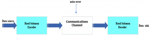
Figure 2 is an example of a standard RS code system.
Figure 2. Code Reed-Solomon system
The equation shown herein demonstrates the utilization of commonly accepted parameters, namely n, k, and t, alongside positive integers denoted as m, whose value must be more than 2, these codes can be created, which is the most efficient way to express Reed Solomon encoding [18].
The Reed Solomon codes' encoding equation is:
$(n, k)=\left(2^m-1,2^m-1-2 t\right)$ (10)
The equation n-k=2 is given. The variable t is used to represent the total amount of parity symbols in the Reed Solomon code. On the other hand, the variable t also denotes the capacity of the code to repair symbols that include faults.
The generating polynomial used in a Reed-Solomon code is shown in the equation indicated.
$g(X)=g_0+g_1 X+g_2 X^2+\cdots+g_{2 t-1} X_{2 t-1}+X^{2 t}$ (11)
The Bose, Chaudhuri, and Hocquenghem (BCH) codes [19] can be thought of as an extension of the Reed and Solomon codes, which were first obtained by Gus Solomon and Irving Reed. It is also possible to encode Reed-Solomon codes methodically. Due to the cyclical structure of binary codes, the systematic technique has been shown to be comparable to the process of binary encoding. In the present scenario, it is possible to conceptualize a message polynomial, indicated as m(X), as undergoing a shift operation within the stages of a code word register, with each step represented by k. Subsequently, a parity polynomial, written as p(X), is appended to the shifted polynomial. This phenomenon is commonly observed in the stages that are positioned towards the extreme left, specifically indicated by the n-k locations. As a result, a shift can be introduced into the message polynomial by multiplying m(X) by Xn-k. Divide the result by the generator polynomial, g(X), and you get the following equation:
$X^{n-k} m(X)=q(X) g(X)+p(X)$ (12)
The polynomials q(X) and p(X) respectively denote the quotient and remainder. The decoding of Reed Solomon codes can be comprehended by utilizing the viewpoints and analyzes of the early researchers. It is generally accepted that system failures caused the codewords to get corrupted during the communication signal's transmission. that academics have used to explain the Reed-Solomon codes are systematically encoded using (n-k) stage and register shifters [20].
The implementation of the (LDPC) algorithm involves the utilization of a parity search array, denoted as H, which is composed of N columns and M rows, resulting in a matrix with dimensions [M×N]. LDPC codes are mostly composed of a significant quantity of zeros and a relatively small quantity of ones. In other words, systematic LDPC codes have been developed to differentiate specific attributes. Based on the established criterion, each row and column must contain a unique numerical value of 1, referred to as the column weight and the row weight, respectively. However, there is a discrepancy between the weights assigned to the columns and those assigned to the rows. The LDPC code, characterized by the parameters (N, j, k), is governed by a set of well-defined rules. Here, N denotes repetition, while j and k represent the column and row weights of the LDPC code, respectively.
The equation 1-y/k=1-M/N represents the encoding rate for LDPC codes. The following is a depiction of the parity-check array featuring an eight-bit coding capacity [21].
$v_1 v_2 \cdots \cdots \cdots v_x$
$H=\left[\begin{array}{llllllll}0 & 1 & 0 & 1 & 1 & 0 & 0 & 1 \\ 1 & 1 & 1 & 0 & 0 & 1 & 0 & 0 \\ 0 & 0 & 1 & 0 & 0 & 1 & 1 & 1 \\ 1 & 0 & 0 & 1 & 1 & 0 & 1 & 0\end{array}\right] \begin{gathered}c_1 \\ c_2 \\ \vdots \\ c_y\end{gathered}$,
x=1, 2, …, N and y=1, 2, ..., M
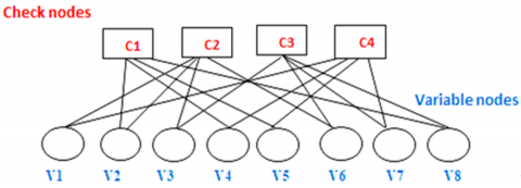
Figure 3 displays a graphical representation of LDPC codes. Specifically, a new H matrix configuration is used, in addition to the Tanner graph, which displays the check node groups and variable nodes every matrix row and column.
The encoding process involves the utilization of a generating matrix to transform data bits into code words. A correlation has been seen between the generating matrix and the parity check matrix. The standard form is capable of yielding the provided parity check matrix [22].
$H=\left[A \mid I_{(n-k)}\right]$ (13)
The symbol H represents the parity check matrix. Several key factors contribute to the generation of code words. $I_{(n-k)}$ is identity matrix and generator matrix is:
$G=\left[I_K \mid A^T\right]$ (14)
The codeword C will be produced in the following manner:
$C=U G$ (15)
The block associated to the information bits is denoted by the symbol U, whereas the generator matrix is represented by the symbol G. The verification process for a valid code-word should be conducted in the following manner:
$H C^T=0$ (16)
In this context, the symbol (.)T denotes the transpose operation applied to a matrix. If the outcome in Eq. (16) is not equal to zero, it indicates that C is invalid. Consequently, the error correcting process will be employed in this scenario.
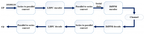
Hard decisions and soft decisions are the two main categories of decisions that are included in the iterative parity check decoder. For soft judgments, a message-passing method called the Sum-Product Method (SPA) is employed. Each bit's input is represented as the probability of earlier knowledge obtained from the channel. Previous study [23] indicates that there are three different forms of SPA classification: Probability Domain, Log Domain, and Min-Sum SPA. The classification is predicated upon the structural composition of the message exchanges occurring between variable nodes and check nodes. The DiPPM system model using LDPC coding is displayed in Figure 4.
Figure 3. LDPC codes represented graphically
Figure 4. DiPPM system model with LDPC coding
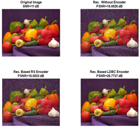
Based on the outcomes of the simulation, it can be observed that LDPC codes significantly enhance the efficiency of DiPPM transmission by reducing the photon count. When utilized at the prescribed coding rate of 3/4, the statistical analysis reveals that the DiPPM coded system exhibits a performance improvement of 5.12 dB compared to the uncoded system. The performance of the system is enhanced when the LDPC as shown in Figure 5 codeword is increased, resulting in a reduction in the bit error rate (BER). The findings indicate that both the coding style and the system employed do not have a discernible influence on the optimal code rate of LDPC codes. The utilization of an LDPC code with DiPPM is seen more advantageous compared to the utilization of an RS code, as evidenced by the observed outcomes.
Figure 5. Comparation between without encoder and with encoder
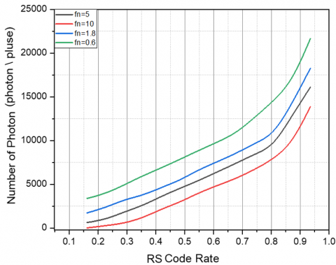
In Figure 6, a comparative analysis is presented, examining the photon count in each pulse for both the DiPPM approach and the RS Code. This analysis takes into account various normalized fiber bandwidths (fn). Assuming an adjusted bandwidth, there is a positive correlation between the number of photons in each pulse and the RS code rate. As the code rate is augmented, there is a concomitant augmentation in the number of photons inside a designated bandwidth.
Figure 6. The correlation between the number of photons and the rate of Reed-Solomon coding at various adjusted bandwidths
The relationship between the adjusted bandwidth and the transmission efficiency of both coded and uncoded DiPPM systems is shown in Figure 7. The employment of Reed-Solomon coding in the coded dicode pulse position modulation (DiPPM) scheme results in better transmission efficiency, especially in channels that have poor dispersiveness. The need for more bandwidth to accommodate the redundancy symbols in RS coding is the likely cause of this issue.
Figure 7. The correlation between the Reed-Solomon (RS) code rate and transmission efficiency for various normalized bandwidth values
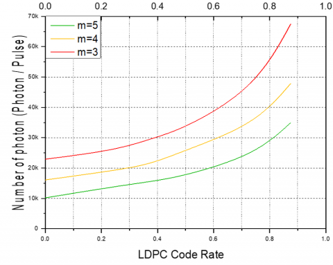
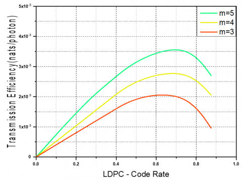
It seems possible to compute the minimum numbers of photons at various LDPC coding rates and constant normalized bandwidth (fn=0.6). It's important to note that the system made the least possible mistakes in Figures 8 and 9.
Figure 8. A comparison between the amount of photons and the LDPC code rate at various code levels
Figure 9. The effect of LDPC code rate on coded OPPM system transmission efficiency
For comparison, Figure 10 shows the associated results of the number of photons for uncoded DiPPM, coded DiPPM with RS, and coded DiPPM with LDPC. The initial operational bandwidth varies from system to system.
Figure 10. Comparation between without encoder and with encoder
The program for implementing the DiPPM system with RS and LDPC codes was developed using MATLAB software. The data obtained by the DiPPM system provided validation for the theoretical framework of the DiPPM approach. When the signal-to-noise ratio (SNR) reaches or exceeds 12dB, the use of the RS and LDPC coding scheme is effective in mitigating errors that adversely impact the integrity of the transmitted data in the Differential Pulse Position Modulation (DiPPM) method. The RS and LDPC code system should ideally function at its optimal code rate. The simulation testing findings indicate that the utilization of the LDPC decoder leads to a notable enhancement in the transmission efficiency of the DiPPM system by reducing the photon count. Furthermore, empirical evidence has shown that the utilization of the (LDPC) code in the system results in a notable enhancement of over 5.12 decibels when compared to systems that do not incorporate the LDPC code.
[1] Islam, M., Jin, S.Z. (2019). An overview research on wireless communication network. Advances in Wireless Communications and Networks, 5(1): 19-28. https://doi.org/10.11648/j.awcn.20190501.13
[2] Sklar, B. (2021). Digital Communications: Fundamentals and Applications. Pearson.
[3] Sibley, M.J. (2003). Dicode pulse-position modulation: A novel coding scheme for optical-fibre communications. IEE Proceedings-Optoelectronics, 150(2): 125-131. https://doi.org/10.1049/ip-opt:20030386
[4] Yazdani, R., Ardakani, M. (2007). An efficient analysis of finite-length LDPC codes. In 2007 IEEE International Conference on Communications, Glasgow, UK, pp. 677-682. https://doi.org/10.1109/ICC.2007.116
[5] Andrews, K.S., Divsalar, D., Dolinar, S., Hamkins, J., Jones, C.R., Pollara, F. (2007). The development of turbo and LDPC codes for deep-space applications. Proceedings of the IEEE, 95(11): 2142-2156. https://doi.org/10.1109/JPROC.2007.905132
[6] Calzolari, G.P., Chiani, M., Chiaraluce, F., Garello, R., Paolini, E. (2007). Channel coding for future space missions: New requirements and trends. Proceedings of the IEEE, 95(11): 2157-2170. https://doi.org/10.1109/JPROC.2007.905134
[7] Hou, J.L., Siegel, P.H., Milstein, L.B. (2001). Performance analysis and code optimization of low density parity-check codes on Rayleigh fading channels. IEEE Journal on Selected Areas in Communications, 19(5): 924-934. https://doi.org/10.1109/49.924876
[8] Djordjevic, I.B. (2013). On the irregular nonbinary QC-LDPC-coded hybrid multidimensional OSCD-modulation enabling beyond 100 Tb/s optical transport. Journal of Lightwave Technology, 31(16): 2669-2675. https://doi.org/10.1109/JLT.2013.2272328
[9] Song, H.Z., Todd, R.M., Cruz, J.R. (2000). Low density parity check codes for magnetic recording channels. IEEE Transactions on Magnetics, 36(5): 2183-2186. https://doi.org/10.1109/20.908351
[10] Kurkoski, B.M., Siegel, P.H., Wolf, J.K. (2002). Joint message-passing decoding of LDPC codes and partial-response channels. IEEE Transactions on Information Theory, 48(6): 1410-1422. https://doi.org/10.1109/TIT.2002.1003830
[11] Li, H., Liu, H., Vafi, S. (2014). Bipolar chaotic pulse position modulation communication system based on cyclic LDPC. EURASIP Journal on Wireless Communications and Networking, 2014: 1-9. https://doi.org/10.1186/1687-1499-2014-105
[12] Costello, D.J., Hagenauer, J., Imai, H., Wicker, S.B. (1998). Applications of error-control coding. IEEE Transactions on Information Theory, 44(6): 2531-2560. https://doi.org/10.1109/18.720548
[13] Al-Nedawe, B.M., Buhafa, A.M., Sibley, M.J., Mather, P.J. (2013). Improving error performance of dicode pulse position modulation system using forward error correction codes. In 2013 21st Telecommunications Forum Telfor (TELFOR), Belgrade, Serbia, pp. 331-334. https://doi.org/10.1109/TELFOR.2013.6716237
[14] Ahfayd, M.H., Farhat, Z.A., Sibley, M.J., Mather, P.J., Lazaridis, P.I. (2017). Visible light communication based system using high power LED and dicode pulse position modulation technique. In 2017 25th Telecommunication Forum (TELFOR), Belgrade, Serbia, pp. 1-4. https://doi.org/10.1109/TELFOR.2017.8249488
[15] Cryan, R.A., Sibley, M.J. (2006). Minimising intersymbol interference in optical-fibre dicode PPM systems. IEE Proceedings-Optoelectronics, 153(3): 93-100. https://doi.org/10.1049/ip-opt:20050028
[16] Cryan, R.A., Unwin, R.T. (1992). Reed—Solomon coded homodyne digital pulse position modulation. IEE Proceedings I (Communications, Speech and Vision), 139(2): 140-146. https://doi.org/10.1049/ip-i-2.1992.0021
[17] Cryan, R.A., Elmirghani, J.M.H.M.O. (1994). Reed-solomon coded optical PPM employing PIN-FET receivers. In Proceedings of ICC/SUPERCOMM'94 - 1994 International Conference on Communications, New Orleans, LA, USA, pp. 126-130. https://doi.org/10.1109/ICC.1994.369009
[18] Massey, J. (1965). Step-by-step decoding of the Bose-Chaudhuri-Hocquenghem codes. IEEE Transactions on Information Theory, 11(4): 580-585. https://doi.org/10.1109/TIT.1965.1053833
[19] Levy, S., Ferreira, K.B. (2019). Space-efficient reed-Solomon encoding to detect and correct pointer corruption. In Euro-Par 2019 International Workshops, Göttingen, Germany, pp. 657-668. https://doi.org/10.1007/978-3-030-48340-1_50
[20] Shongwe, T.C. (2014). Synchronization with Permutation Codes and Reed-Solomon Codes. University of Johannesburg, South Africa.
[21] Hussein, Y.M., Mutlag, A.H., Al-Nedawe, B.M. (2021). Comparisons of soft decision decoding algorithms based LDPC wireless communication system. IOP Conference Series: Materials Science and Engineering, 1105(1): 012039. https://doi.org/10.1088/1757899X/1105/1/012039
[22] Dhanavath, R.K. (2022). An efficient technique to implement encoder and decoder in communication system for error detection and correction Golay CodeUsing Golay code. Research Square. https://doi.org/10.21203/rs.3.rs-1297984/v1
[23] Abed, A.M., Hasan, F.S. (2022). The performance evaluation of multi user OFDM orthogonal chaotic vector shift keying supported by LDPC. Journal of Engineering and Sustainable Development, 26(3): 62-72. https://doi.org/10.31272/jeasd.26.3.7